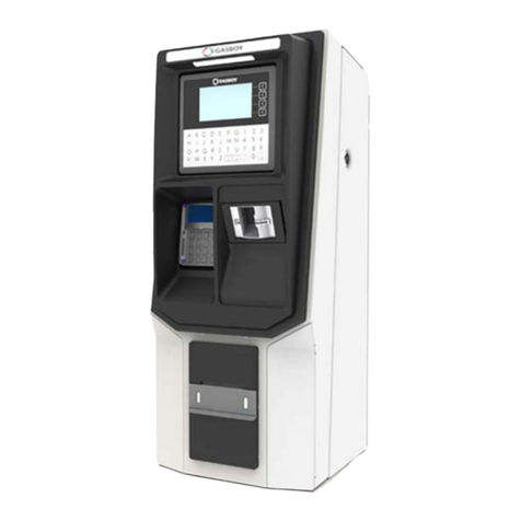
Gasboy SERIES 1000 User manual

SERIES 1000
FUEL MANAGEMENT SYSTEM
OPERATION MANUAL
FOR CANADA
C08948
GASBOY INTERNATIONAL LLC


GASBOY
SERIES 1000
FUEL MANAGEMENT SYSTEM
OPERATION MANUAL
FOR CANADA
Software Version 10
C08948
Rev. 05/29/03
GASBOY INTERNATIONAL LLC
LANSDALE, PA

Copyright 2003 by Gasboy International LLC
All rights reserved.
The information in this document is confidential and proprietary. No further disclosure thereof
shall be made without permission from Gasboy International LLC.
Gasboy International LLC believes that the information in this document is accurate and reliable.
However, we assume no responsibility for its use, nor for any infringements of patents or other
rights of third parties resulting from its use. We reserve the right to make any changes at any time
without notice.

05/29/03 Contents-1
CONTENTS
Section 1: INTRODUCTION
Overview ................................................................................................... 1-1
System Features....................................................................................... 1-2
Standard Features............................................................................... 1-2
Optional Features ................................................................................ 1-3
Documentation/Getting Started................................................................. 1-5
How to Use This Book............................................................................... 1-6
Section 2: FUELING WITH THE SERIES 1000......................................................... 2-1
Section 3: COMMUNICATING WITH THE SERIES 1000
Communication Ports................................................................................ 3-1
Communication Protocol........................................................................... 3-1
Communication Terminations.................................................................... 3-2
Initiating Communication........................................................................... 3-3
LS - Load Sign-on Password..................................................................... 3-4
Lost or Forgotten Password...................................................................... 3-5
Section 4: SERIES 1000 OPERATING MODES
System Modes........................................................................................... 4-1
Entering and Exiting Command Mode....................................................... 4-2
Enter Command Mode - CTRL F......................................................... 4-2
Exit Command Mode- EX Command................................................... 4-2
Override Other Port - CTRL B.............................................................. 4-2
Entering Commands and Other System Input........................................... 4-3
HE - Help Command................................................................................. 4-4
Section 5: SYSTEM MAINTENANCE COMMANDS
Description ................................................................................................ 5-1
System Configuration Parameters ............................................................ 5-2
SC - Load or Change System Configuration............................................. 5-4
Changing the System Configuration .................................................... 5-6
PS - Print System Configuration................................................................ 5-8
LD - Load Date and Time.......................................................................... 5-9
PD - Print Date and Time.......................................................................... 5-10
SD - Load Site Down Time........................................................................ 5-11
PR - Print Program Revision and Date...................................................... 5-12
LK - Load Pin Key ..................................................................................... 5-13
LC - Print Last Card(s) Read..................................................................... 5-14
MO - Display Output By Screen (More) .................................................... 5-16

GASBOY Series 1000
Contents-2 05/29/03
Section 6: CARD VALIDATION COMMANDS
Overview ................................................................................................... 6-1
Card Validation Commands................................................................. 6-1
VA - Validate All Cards.............................................................................. 6-2
VC - Validate a Card ................................................................................. 6-3
Validate a Single Card ......................................................................... 6-3
Validate a String of Assorted Cards..................................................... 6-3
Validate a Range of Cards................................................................... 6-4
IA - Invalidate All Cards............................................................................. 6-5
IC - Invalidate a Card ................................................................................ 6-6
Invalidate a Single Card....................................................................... 6-6
Invalidate a String of Assorted Cards................................................... 6-6
Invalidate a Range of Cards................................................................. 6-7
CC - Check Card Validation...................................................................... 6-8
PV - Print Valid Card List........................................................................... 6-9
PI - Print Invalid Card List.......................................................................... 6-10
Card Validation/Invalidation Error Messages ............................................ 6-11
Section 7: TANK INVENTORY COMMANDS
Description ................................................................................................ 7-1
Tank Inventory Commands.................................................................. 7-1
LI - Load Tank Inventory ........................................................................... 7-2
AI - Add to Tank Inventory......................................................................... 7-3
SI - Subtract from Tank Inventory ............................................................. 7-4
TI - Print Tank Inventory............................................................................ 7-5
LR - Load Inventory Reorder Point ........................................................... 7-6
Section 8: PUMP COMMANDS
Description ................................................................................................ 8-1
Pump Commands................................................................................ 8-1
LP - Load Pump Data................................................................................ 8-2
Defining Unit Price ............................................................................... 8-2
Assigning Timeout Values.................................................................... 8-2
Loading the Data.................................................................................. 8-3
Changing Pump Data........................................................................... 8-4
PP - Print Pump Data................................................................................ 8-5
EP - Enable a Pump.................................................................................. 8-6
DP - Disable a Pump................................................................................. 8-7
AP - Activate a Pump................................................................................ 8-9
IP - Inactivate a Pump............................................................................... 8-10
ZP - Zero Pump Totalizers........................................................................ 8-11
XP - Print Timeouts and Pulses ................................................................ 8-12
Section 9: TRANSACTION COMMANDS
Transaction Printing Options..................................................................... 9-1
Transaction Commands....................................................................... 9-1
Transaction Headings ............................................................................... 9-2
Price Data Format Effect on Headings................................................. 9-2
Transaction Printing with the Link Terminal and Okidata Printer......... 9-2
PT - Print Transactions.............................................................................. 9-3
ST - Print Sorted Transactions.................................................................. 9-4

Introduction
05/29/03 Contents-3
SS - Print Transactions for Specified Number
Within a Field........................................................................................... 9-5
PH - Print Compacted Transactions With Host
Interaction................................................................................................ 9-6
PC - Print Compacted Transactions.......................................................... 9-8
RT - Reset Transaction File...................................................................... 9-9
RP - Reset Transaction Pointer................................................................. 9-10
LN - Load Transaction Number................................................................. 9-11
Obtaining a Printout of Specific Transactions ........................................... 9-12
Transaction Messages.............................................................................. 9-13
Section 10: FUELING RESTRICTION COMMANDS
Description ................................................................................................ 10-1
Fueling Restriction Commands............................................................ 10-1
LF - Load Fuel Authorizations................................................................... 10-2
PF - Print Fuel Authorizations ................................................................... 10-3
LL - Load Fuel Limitations......................................................................... 10-4
PL - Print Fuel Limitations......................................................................... 10-5
Section 11: POLLING TRANSACTION INFORMATION
Methods of Polling..................................................................................... 11-1
Polling Using the PT Command........................................................... 11-1
Polling Using the ST Command........................................................... 11-1
Polling Using a PC or Computer.......................................................... 11-2
OPTIONAL FEATURES
Section 12: ACTIVATE PUMP (AP) DATA ENTRY OPTION
Description ................................................................................................ 12-1
Software Options Affected by Activate Pump
with Data Entries..................................................................................... 12-3
Section 13: DUAL LOCKOUT OPTION
Description ................................................................................................ 13-1
Changes in Standard Commands............................................................. 13-1
Section 14: FUEL ALLOCATION OPTION
Description ................................................................................................ 14-1
Allocation Commands.......................................................................... 14-1
Fuel Allocation Examples..................................................................... 14-2
AO - Allocation Offset................................................................................ 14-3
LA - Load Allocation.................................................................................. 14-4
ML - Multiple Load of Allocation................................................................ 14-5
AA - Add to Allocation ............................................................................... 14-6
MA - Multiple Add to Allocation ................................................................. 14-7
SA - Subtract from Allocation.................................................................... 14-8
MS - Multiple Subtract from Allocation...................................................... 14-9
CA - Check Allocation ............................................................................... 14-10
AT - Configure to Print All Totalizers......................................................... 14-11
NZ - Configure to Print Non-zero Totalizers.............................................. 14-12

GASBOY Series 1000
Contents-4 05/29/03
PA - Print Allocation Table ........................................................................ 14-13
MP - Print Range of Allocation.................................................................. 14-14
Transaction Headings with the Fuel
Allocation Option.................................................................................. 14-15
Section 15: FUEL DELIVERY AND DIPSTICK CARD OPTION
Description ................................................................................................ 15-1
Fuel Deliveries........................................................................................... 15-2
Dipstick Readings...................................................................................... 15-3
Transaction Headings with the Fuel Delivery/
Dipstick Option........................................................................................ 15-4
Section 16: GATE CONTROLLER OPTION
Description ................................................................................................ 16-1
Gate Controller Commands ................................................................. 16-1
LG - Load Gate Timeout ........................................................................... 16-2
PG - Print Gate Timeout............................................................................ 16-3
AG - Activate Gate .................................................................................... 16-4
Transaction Headings with the Gate
Controller................................................................................................. 16-5
Compacted Format with the Gate Controller............................................. 16-5
Changes in Standard Commands............................................................. 16-6
Software Options Affected by Gate
Controller................................................................................................. 16-7
Data Entries on Activate Gate (AG) Command Option........................ 16-7
Compacted Print Format with L/100KM or LPH Option ....................... 16-8
Additional Software Options for Gate
Controller................................................................................................. 16-9
Disable Memory Full Protection........................................................... 16-9
Section 17: LOADABLE BASE PUMP OPTION
Description ................................................................................................ 17-1
Changes in Standard Commands............................................................. 17-2
Section 18: MANUAL KEYPAD ENTRY OPTION
Description ................................................................................................ 18-1
Section 19: L/100KM or LPH OPTION
Description ................................................................................................ 19-1
Vehicle File Commands....................................................................... 19-2
CV - Clear Vehicle File.............................................................................. 19-3
LV - Load/Edit a Vehicle Record............................................................... 19-4
Load a New Vehicle Record................................................................. 19-4
Edit an Existing Vehicle Record........................................................... 19-5
RV - Remove a Vehicle Record ................................................................ 19-7
LO - Load Odometer/Hours....................................................................... 19-8
IV - Initialize Vehicle File........................................................................... 19-9
VF - Print Vehicle File................................................................................ 19-10
LM - Load Maximum Kilometers/Hours Between Fuelings ....................... 19-12

Introduction
05/29/03 Contents-5
LE - Load Ending Odometer/Hours........................................................... 19-13
CR - Check Vehicle Record ...................................................................... 19-14
EC - Enable L/100KM or LPH Calculation and Reasonable
Odometer/Hours Check For All Vehicles ............................................. 19-15
DC - Disable L/100KM or LPH Calculation and Reasonable
Odometer/Hours Check For All Vehicles ............................................. 19-16
Transaction Processing............................................................................. 19-17
L/100KM Transaction Processing........................................................ 19-17
LPH Transaction Processing................................................................ 19-18
Transaction Headings ............................................................................... 19-20
L/100KM Option................................................................................... 19-20
LPH Option .......................................................................................... 19-20
Changes in Standard Commands............................................................. 19-21
L/100KM (or LPH) Messages.................................................................... 19-23
Section 20: MULTI-LEVEL PASSWORD OPTION
Description ................................................................................................ 20-1
CP - Super User Authorization of Commands........................................... 20-2
Section 21: PUMP SWITCH TIMER OPTION
Description ................................................................................................ 21-1
Changes in Standard Commands............................................................. 21-2
Section 22: REASONABLE ODOMETER/HOURS CHECK OPTION
Description ................................................................................................ 22-1
Vehicle File Commands....................................................................... 22-2
CV - Clear Vehicle File.............................................................................. 22-3
LV - Load a Vehicle Record ...................................................................... 22-4
RV - Remove a Vehicle Record ................................................................ 22-5
LO - Load Odometer/Hours....................................................................... 22-6
VF - Print Vehicle File................................................................................ 22-7
LM - Load Maximum Kilometers Between Fuelings.................................. 22-8
CR - Check Vehicle Record ...................................................................... 22-9
Changes in Standard Commands............................................................. 22-10
Transaction Headings with the Reasonable
Odometer/Hours Check....................................................................... 22-12
Reasonable Odometer/Hours Messages.................................................. 22-12
Section 23: RECEIPT PRINTER OPTION
Description ................................................................................................ 23-1
Fueling Procedure..................................................................................... 23-2
GR - Get Receipt Command..................................................................... 23-3
Changes in Standard Commands............................................................. 23-4
Additional Receipt Printer Option - Multiple Receipts................................ 23-6
Receipt Printer Messages......................................................................... 23-8
Section 24: SUPERVISOR CARD OPTION
Description ................................................................................................ 24-1
Mag Card Systems............................................................................... 24-1
Optical Card Systems .......................................................................... 24-2
Fueling with a Supervisor Card................................................................. 24-3

GASBOY Series 1000
Contents-6 05/29/03
Section 25: TANK MONITOR INTERFACE
Description ................................................................................................ 25-1
TM - Tank Monitor Link Command............................................................ 25-2
Terminate Tank Monitor Communications Link......................................... 25-3
ENQ (CTRL E) Termination................................................................. 25-3
Timeout Termination............................................................................ 25-4
Tank Monitor Error Messages................................................................... 25-5
Section 26: PREVENTIVE MAINTENANCE................................................................ 26-1
Section 27: RECEIPT PRINTER MAINTENANCE
Printer Description..................................................................................... 27-1
Switches and Settings............................................................................... 27-1
Printer Status Board............................................................................. 27-2
Status Board Switches......................................................................... 27-2
Status Board Lamps............................................................................. 27-3
Controller Board DIP Switch Settings .................................................. 27-3
Accessing the Printer for Maintenance or Service .................................... 27-4
Changing the Paper .................................................................................. 27-4
Removing the Paper ............................................................................ 27-4
Installing the Paper .............................................................................. 27-5
Changing the Ribbon................................................................................. 27-5
Removing Old Ribbon Spools.............................................................. 27-5
Installing New Ribbon Spools .............................................................. 27-6
Adjusting Cutter Blades............................................................................. 27-7
Adjust After Incomplete Cuts................................................................ 27-7
Adjust After Paper Jams ...................................................................... 27-7
Appendix A COMMERCIAL FUELING NETWORK (CFN)
Appendix B SETUP OF PERIPHERAL EQUIPMENT
INDEX
WARRANTY

Introduction
05/29/03 Contents-7
FIGURES AND TABLES
Figures
27-1 Card System with Receipt Printer................................................................................ 27-1
27-2 Printer Status Board.................................................................................................... 27-2
27-3 DIP Switches............................................................................................................... 27-3
27-4 Printer Side View......................................................................................................... 27-4
27-5 Ribbon Installation Sequence...................................................................................... 27-6
27-6 Cutter Bar Adjustment Screw...................................................................................... 27-7
Tables
27-1 Status Board Switches ................................................................................................ 27-2
27-2 Status Board Lamps.................................................................................................... 27-3
27-3 DIP Switch Settings..................................................................................................... 27-3


05/29/03 1-1
Section 1
INTRODUCTION
This manual provides descriptions and operating procedures for your GASBOY Series 1000 Fuel
Management System. It also contains information for users of the Commercial Fueling Network
(CFN). These users have differences in their Series 1000 systems that are documented in
Appendix A of this book. This CFN is not to be confused with the GASBOY CFN system.
You should review this manual before your system start-up and reference it as you operate the
system.
OVERVIEW
The GASBOY Series 1000 Fuel Management System is a card-activated, microprocessor-based
fuel control and data acquisition system.
The Series 1000 System is designed to gather and record specific information about your fuel
management operation. You set up the Series 1000 by defining your configuration (tanks, pumps,
etc.). See Documentation/Getting Started later in this section.
Once your Series 1000 is operational, a typical scenario might be: A valid user drives his vehicle
into the fueling area. He places his card into the Series 1000, which reads and validates it. If a
second card is required, he then inserts it and the system validates that card. Then, the system
requests various pieces of information depending on the coding on the card (i.e., personal
identification numbers, odometer readings, etc.) Then it asks which pump he will be using. If
everything checks out within the system, the pump is activated and the fueling process begins.
When the fueling process ends and the user replaces the pump nozzle in its holder, the Series
1000 records transaction information in memory, and prints it out at the data terminal or logger, if
setup permits. Based on the transaction information, the Series 1000 decrements the tank
inventory and increments the pump totalizers.

GASBOY Series 1000
1-2 05/29/03
SYSTEM FEATURES
Using a data terminal, or computer with interface, connected to one of two communications ports,
you can issue commands and retrieve information from the Series 1000.
Standard Features
The standard features of this system include:
● 24-hour, unattended, controlled access to your fuel dispensing equipment.
● Standard Series 1000 simultaneously controls two hose outlets and can be expanded in two
hose increments to control up to eight. Supports pulsing rates of dollar (one penny per
pulse); or quantity (1, 10, 100, 250, 500, or 1000 pulses per unit of product). The pulse rate
selection switch is located in an area sealable by weights and measures for retail
applications.
● Visual prompting messages displayed on an eye-level 20-character liquid crystal display
(LCD) to guide the user through the fueling sequence.
● Access to the system restricted individually by card number or, optionally, by an additional 4-
digit field. CFN systems users are restricted via a 7-digit card number and no additional
fields.
● Controlled access to product type, using nine loadable authorization codes, card encoded.
● Limits on amount of fuel dispensed in a transaction, using 10 loadable limit codes, card
encoded.
● Automatic, immediate, transaction printing for hard copy backup or audit trail. Printing
includes: transaction number, date, time, card number, identification field #1 (e.g., employee
number), identification field #2 (e.g., vehicle number), pump used, fuel type and quantity
dispensed, price data (unit and total, if configured), odometer reading, and a transaction
status message.
● Automatic recording and storage of all transactions in system memory for later recall.
● Transaction printing in a variety of formats to meet your information requirements.
● Printing and storage of pricing data. Available options depend on pulser type. With dollar
pulsers, the system can print unit price only or both unit and total price. With quantity pulsers,
the system can print only unit and total price.
● Two asynchronous ports (both configurable to RS-232 or RS-422) for terminal and/or
computer communications.
● For additional report processing, the ability to interface with communications and report
software for IBM, and compatible, personal computers. Software is extra.
● A perpetual fuel inventory, maintained for up to eight tanks. Inventory adjustments are
automatically made with each transaction and can be adjusted at the data terminal to ensure
maximum inventory accuracy.
● Maintains up to eight resettable pump totalizers.

Introduction
4019 1-3
● A magnetic stripe insertion reader or an optional optical card reader. Optical readers are not
supported for CFN systems.
● An emergency shutdown button on the cabinet face to quickly shut down dispensing
equipment in case of emergency.
● Built-in AC and RS-422 transient protection reduces problems caused by power surges.
● To safeguard the system in a power failure, AC and DC power fail detect, deadman timer,
and pump control fail-safe circuits ensure an orderly shutdown so the system can return to
normal operation upon restoration. The system clock and memory are backed by batteries to
maintain the time and transaction data during power failures.
Optional Features
In addition to the standard features, your Series 1000 may have one or a combination of these
available options:
● Activate Pump (AP) Data Entry Option - allows you to enter card data (Card, ID Field 1,
and ID Field 2) and an odometer/hours reading at the data terminal before activating a pump.
● Dual Lockout Option - allows you to restrict system access by locking out a second 4-digit
field of your choice (in addition to card number). Dual lockout is not supported for
Commercial Fueling Network (CFN) systems.
● Extended Pump Timeouts Option - allows you to extend the standard maximum timeout
from 180 seconds to 3600 seconds (1 hour).
● Fuel Allocation Option - allows you to allocate predetermined amounts of fuel to a set
number of users.
● Fuel Delivery and Dipstick Option - enables you to accept and record fuel delivery and
dipstick reading data using special cards at the Series 1000.
● Gate Controller Option - enables you to use a dedicated Series 1000 to control a gate.
● Hours Option - Provides prompts at the LCD for users who record fuel consumption by an
hour meter instead of an odometer.
● Loadable Base Pump Option - allows you to assign different starting pump numbers for
sites having more than one Series 1000.
● Manual Keypad Entry Option - provides an additional field that allows you to request
specific input from the Series 1000 user. This option is a standard feature for Commercial
Fueling Network (CFN) systems.
● L/100KM (or LPH) Option - calculates and maintains liters-per-100 kilometers tallies for a
set number of your vehicles. This option can also be ordered to calculate liters-per-hour for
users’ equipment operating on an hour meter.
● Multi-Level Password Option - allows two levels of password access: super user, which
can access all commands; and standard user, which can access only commands authorized
by the super user.

GASBOY Series 1000
1-4 05/29/03
● Pump Switch Timer Option - allows you to prevent fueling at a pump when the handle has
been left on from a previous transaction.
● Reasonable Odometer/Hours Check Option - provides an odometer validity check for a set
number of your vehicles. This option can also be ordered to provide a reasonable hours
check for users’ equipment operating on an hour meter.
● Receipt Printer Option - allows you to obtain a fueling transaction receipt.
● Supervisor Card Option - allows you to use a specially encoded supervisor card to
manually enter card information at the Series 1000 keypad.
● Tank Monitor Interface - enables you to communicate with a GASBOY TMS 500 or a
Veeder-Root TLS, or an EBW AutoStik tank monitoring system using the Series 1000 as an
interface.
If problems arise or if you need assistance or information on options, call your authorized service
representative or GASBOY customer service at 1-800-444-5529.

Introduction
4019 1-5
DOCUMENTATION/GETTING STARTED
The following documentation is provided with the Series 1000 Fuel Management System:
● Installation Manual, C08922
● Card Encoding Manual, C08924
● Card Encoding Manual for Commercial Fueling Networks, C08370
● Operation Manual, C08923
● Diagnostic Manual, C08925
In addition, your authorized service representative (ASR) is provided with the following manual:
● Start-up Manual, C08921
When you get to this point, we assume:
● your system has been installed and tested (Reference: Installation Manual).
● your ASR has started up your system, and helped you perform necessary tests (Reference:
Start-up Manual).
● your ASR has helped you with your initial configuration (Reference: Start-up Manual and
Operation Manual)
When you configure your system you need to know:
- number of pumps (outlets)
- number of tanks
- pulser type
- pulses per liter or dollar (penny pulsing)
- fuels and fuel codes
- fuel code authorizations and limitations
- communications port settings
- site shutdown start and end times
- the type of lockout file you wish to create
Your ASR will help you perform these commands:
SC configure your system
MO allows you to view data one screen at a time on your CRT (if desired)
RT initialize transaction file
LN load starting transaction number
LD load system date and time
LK load 4-digit PIN key (assigned on card layout)
SD load shutdown start and end times
LI load initial inventory for each tank
LR load an inventory reorder point for each tank
LP assign specific fuels, tanks, totalizer readings, and timeouts to your pumps
LL assign maximum fuel quantities to limitation codes
LF assign fuel codes to authorization codes
VA or IA validate or invalidate all cards depending on the type of card file you’ve chosen
(negative or positive)
● Your cards should be encoded (Reference: Card Encoding Manual or Card Encoding Manual
for Commercial Fueling Networks, C08370).

GASBOY Series 1000
1-6 05/29/03
HOW TO USE THIS BOOK
This book is written in first person aimed at the system operator. Reviewing these items will help
you as you use this book:
● We use the term, the system to describe the Series 1000.
● When procedures say you, we infer that you are the system operator at the data terminal.
● When we say the user, we infer that the user is the person currently at the Series 1000 card
system.
● Nearly all of the procedures in this book are initiated and entered from the data terminal.
● When we say on the Series 1000 keypad, we mean you enter data at the card reader.
● When we say, the system displays, we are generally referring to the data terminal display.
When we refer to display messages on the Series 1000, we usually say on the LCD display.
● When we tell you to press keys, either on the data terminal or on the Series 1000 keypad, we
use the key name (i.e., RETURN, ENTER, etc.). The control key (CTRL) is always pressed
with another key. When you see a sequence like CTRL C, it means press the CTRL and C
keys together.
● Data you enter in examples is shown in bold type. All examples shown in this manual are for
the standard Series 1000. See Appendix A for CFN system examples.
● When you see the symbol ↵in examples it means to press RETURN after the entry of data.
● Appendix A in this manual covers information and system differences for members of the
Commercial Fueling Network (CFN) using this system in their network. CFN, in this case,
should not be confused with GASBOY’s CFN System.
The Commercial Fueling Network logo appears throughout this manual to
indicate when a standard Series 1000 command or procedure is handled
differently for Commercial Fueling Network users. When you see the
Commercial Fueling Network logo (shown at right) on a page, refer to the
appropriate subheading in the Appendix for more information.

05/29/03 2-1
Section 2
FUELING WITH THE SERIES 1000
The GASBOY Series 1000 System is designed to guide even untrained users effortlessly through
the operation of the system. A series of prompts, which appear on the Liquid Crystal Display
(LCD), guides the user through the fueling transaction. For additional reference, operating
instructions are printed on the cabinet face.
A typical fueling using a Series 1000 (magnetic or optical card) is accomplished as follows:
1. Position your vehicle adjacent to the fuel dispensing equipment. Be sure to note the
odometer reading (if your system uses this feature).
In its idle state, the Series 1000 LCD display alternates between an ENTER CARD message
and a personalized system message.
2. If you are using a two-card optical system, place the two optical cards on top of each other
(order does not matter) with the cut corner to the left and towards the reader and insert them
into the reader as one card. Skip to Step 6.
If you are using magnetic cards, insert your card fully into the card reader with the magnetic
stripe facing down and to the left. The LCD displays: REMOVE CARD
3. Remove the card. If you leave a card in the reader for more than five seconds, an alarm
sounds to remind you to remove it. If you are using a one-card system, skip to Step 7.
4. If you are using a two-card system, the LCD displays: ENTER SECOND CARD.
5. Insert the second card fully into the card reader with the magnetic stripe facing down and to
the left. The LCD displays: REMOVE CARD.
6. Remove the card(s) from the reader.
7. If your system uses the receipt printer option, go to Step 8.
If your system uses PINs, go to Step 9.
If your system uses odometer readings only, go to Step 10.
If your system uses none of these, go to Step 11.
8. If you have the receipt printer option and a prior transaction (with quantity) receipt is
available, the LCD displays: RECEIPT? 1=YES 0=NO.
To print a transaction receipt, press 1and ENTER. The LCD displays: RECEIPT IS
PRINTING. If you have requested multiple receipts, they print out one after the other. The
system goes to idle and you must reinsert your card(s) to begin a fueling transaction.
If you do not want a receipt, press 0 and ENTER. Skip to Step 9. For more on receipt
printing, see Section 23.

GASBOY Series 1000
2-2 05/29/03
9. If you are required to enter a Personal Identification Number (PIN), the LCD displays: ENTER
P.I.N.
Using the keypad, enter your PIN number and press ENTER. To ensure security, an asterisk
(*) appears for each digit you press. If you make a mistake while entering your PIN, press
CLEAR and enter it again.
You have three tries to enter the correct PIN. After the third unsuccessful try, the display
returns to ENTER CARD and you must start again at Step 2.
If your system uses the Auto Pin Lockout feature, the card is automatically locked out
(invalidated) after the third unsuccessful PIN entry.
10. If you are required to enter an odometer reading, the LCD displays: ENTER ODOMETER or
ENTER HOURS.
Use the keypad to enter the mileage/time that appears on your vehicle’s odometer or hour
meter (up to six digits, no tenths). The digits appear as they are entered. If you make a
mistake, press CLEAR and enter the reading again. When you enter the correct reading,
press ENTER. The LCD prompts: SELECT PUMP
10. Enter the desired pump number (one digit), and press ENTER.
If the pump is available and you are authorized to use it, the LCD displays: PUMP #x IS
READY and you may proceed to dispense fuel.
If PUMP #x IS READY is not displayed, one of the following messages appears:
NO SUCH PUMP
PUMP IN USE!
PUMP DISABLED
INVALID FUEL
You have three tries to select a correct pump. If, after three attempts, the system does not
display PUMP #x IS READY, the display returns to ENTER CARD and you must begin again
at Step 2.
11. When you finish fueling your vehicle, turn off the fuel dispenser handle and return the nozzle
to its holder. The transaction information is automatically recorded in the system’s memory
for later recall. If you are using the Direct Printout feature, the transaction information is
also printed on the data terminal or logger.
Transaction information includes transaction number, card number, identification field 1,
identification field 2, date, time, pump number, product type, quantity dispensed, unit price
and/or unit and total price (if configured), odometer/hours reading, and transaction message.
13. If you have the receipt printer option and you wish to have a receipt, insert and remove your
card. The LCD displays: RECEIPT? 1=YES 0=NO.
To print a transaction receipt, press 1and ENTER. The LCD displays: RECEIPT IS
PRINTING. Multiple receipts print out one after the other. The system goes to idle.
Other manuals for SERIES 1000
1
Table of contents
Other Gasboy Control System manuals
Popular Control System manuals by other brands
Cabrinha
Cabrinha 2010 Powerdrive IDS manual

DSPPA
DSPPA MAG2189 manual
Skov
Skov DOL Technical user guide
EWC Controls
EWC Controls ULTRA-ZONE HK2000 Technical bulletin
A-T Controls
A-T Controls TRIAG M-3POS-115 Installation & maintenance manual
Honeywell
Honeywell Excel 800 LION Installation and commissioning instructions
HEIDENHAIN
HEIDENHAIN ITNC 530 - CONVERSATIONAL PROGRAMMING Service manual
UCS
UCS C-SV 4A user manual
STEPCRAFT
STEPCRAFT M Series operating manual

Fröling
Fröling Lambdatronic SP 3200 Service manual
Carrier
Carrier PRO-DIALOG PLUS 50AZ Installation, operation and maintenance instructions

Daintree
Daintree WWD2-4SM installation guide

