SKC 224-44MTX User manual
www.skcltd.com
Universal Air Sampling Pump
Operating Instructions
This manual covers the following models:
224-44MTX, 224-PCMTX4, 224-PCMTX8

Page 2 224-UMTXM Issue K www.skcltd.com
Purchase Details and Service History
Thank you for choosing an SKC product. Your purchase is covered by our warranty, details of which can be
found inside the rear cover of this manual.
Product Model Number Product Serial Number Date of Purchase
SKC recommends a minimum service interval of one year for this product. The first service is due one year from
the date of purchase, and then at yearly intervals on this date. However, it is the responsibility of the user to
perform a risk assessment to determine the necessary frequency of servicing that is required.
Service Date Service Date Service Date
159
2 6 10
3 7 11
4 8 12
Please note that SKC Ltd are the only authorised service centre in the UK, guaranteeing you access to the full
range of genuine SKC replacement parts. For all other areas a full list of SKC approved distributors and service
centres can be found at www.skcltd.com

www.skcltd.com 224-UMTXM Issue K Page 1
Contents
Intrinsic Safety Information.............................................................................................................................2
Specifications ................................................................................................................................................4
General Information .......................................................................................................................................8
Diagram of the Universal MTX Pump ...........................................................................................................10
Pump Controls Layout.................................................................................................................................12
Getting Started............................................................................................................................................13
Operating the Timer (224-PCMTX8 Only).....................................................................................................16
Low Flow Sampling .....................................................................................................................................20
Troubleshooting...........................................................................................................................................22
Care of the Battery Pack..............................................................................................................................24
Universal MTX Pump Components ..............................................................................................................26
Universal MTX Pump Replacement Parts.....................................................................................................27
Universal MTX Pump Accessories................................................................................................................28
Intrinsic Safety Certification..........................................................................................................................30
Warranty Information ...................................................................................................................................36

Page 2 224-UMTXM Issue K www.skcltd.com
Intrinsic Safety Information
The Universal MTX pump range
• Complies with the EU ATEX Directive 2014/34/EU on equipment intended for use in potentially explosive
atmospheres, as intrinsically safe to EEx ia
II
C T4, for use in Europe.
• The equipment may be used in zones 1 and 2 with flammable gases and vapours with apparatus groups
II
A,
II
B &
II
C and with temperature classes T1,T2,T3,T4.
• The equipment is only certified for use in ambient temperatures in the range -20 to +40°C and should not
be used outside this range.
• The battery pack should not be charged in a hazardous area.
• Use only SKC approved chargers designated for the model.
• The equipment has not been assessed as a safety related device (as referred to in Directive 2014/34/EU
Annex II, clause 1.5).
• The equipment should not be used if damaged in a way that could invalidate intrinsic safety. Such
defects might include cracking of the battery pack enclosure and internal encapsulant such that internal
components or cells are exposed. It is the responsibility of the user to ensure that the pump is in an
acceptable condition for use in hazardous locations.
Important note about intrinsic safety
If you are unsure as to whether the Universal pump you have purchased is suitable for your environment, check
with your site manager or responsible person BEFORE USE that the intrinsic safety rating on the product meets
your site requirements. SKC personnel are unable to recommend the appropriate safety rating for your site.

www.skcltd.com 224-UMTXM Issue K Page 3
Blank Page
Page 4 224-UMTXM Issue K www.skcltd.com
Specifications
All models
• Weight: 915 g
• Casing IP rating: IP20
• Flow range:
1000 - 4000 ml/min (constant flow operation)
5 - 500 ml/min with adapter (constant pressure operation)
• Flow control: ±5% set point constant flow
• Flow indicator: Scale range 0.5 - 5.5 l/min
• Battery pack: NiMH rechargeable, 2.0 Ah, 4.8 V
• Storage & operating temperature: -20°C to +40°C
• Operating humidity: 0 to 95% RH
• Compensation range:
Flow rate
(l/min)
Back Pressure
(inches of water) Typical sample media back pressure:
IOM sampler with GFA filter at 4 l/min =
approximately 10 inches of water
IOM sampler with 0.8µm MCE filter at 2 l/min =
approximately 15 inches of water
1 5 - 30
2 0 - 25
3 0 - 20
4 0 - 10
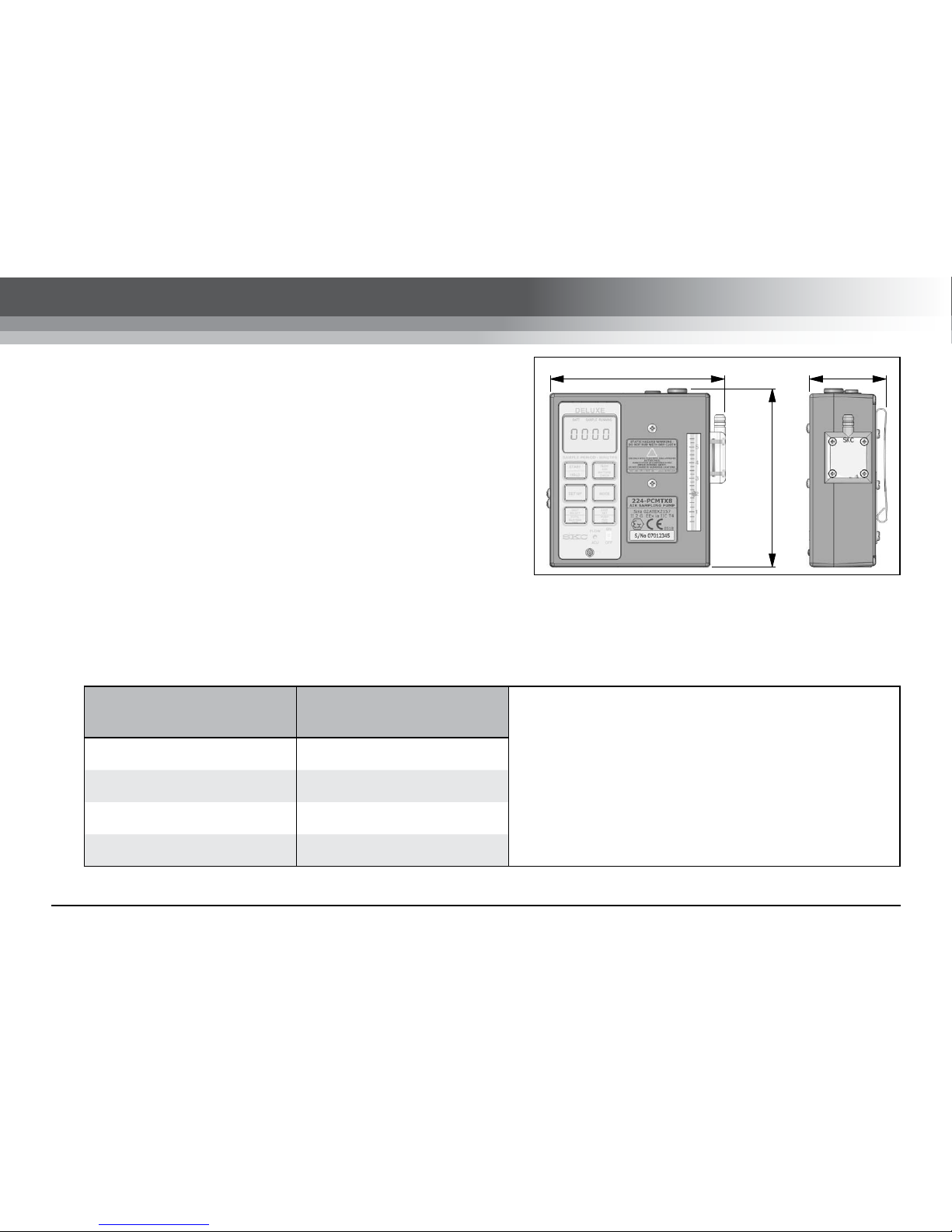
131mm 57mm
133mm

www.skcltd.com 224-UMTXM Issue K Page 5
Specifications
• Typical run time: 8 hours minimum at 3000 ml/min and 20 inches of water back pressure
224-PCMTX4 & 224-PCMTX8 only:
• Timer: Run time display 0 to 9999 minutes
Hold feature to pause pump and timer
Fault shutdown for low battery and high back pressure with timer freeze
224-PCMTX8 only:
• Timer: Delayed start up to 9999 minutes
Timed shut down
Note:
SKC Limited reserve the right to make changes to the specification and design of this product at any time
without prior notice to the end user.

Page 6 224-UMTXM Issue K www.skcltd.com
Specifications
Pump Features
All Models
Battery charging options
SKC offer two battery charger options for the Universal MTX series pumps, a single
charger (Part No. 223-203A) and a five station charger (Part No. 223-103A). Both charger
models provide optimum charging of the NiMH battery packs used in the Universal MTX
series pumps, based on a timed (16 hour) constant current charging phase followed by
a switch to a trickle charging rate to prevent overcharging.
Mains power option
The Universal MTX series pumps can also be powered from the electrical mains supply
using a ‘battery eliminator’ (Part Nos. 223-305B - Euro 2 pin plug, 223-305C UK 3 pin
plug). This accessory comprises a mains adaptor and dummy battery pack which is fitted
to the pump in place of the standard battery pack. Please note that the pump’s ATEX
certification is invalidated when using the battery eliminator, and therefore must not be
used in hazardous areas when the battery eliminator is fitted.
Anti-tamper cover The pump controls are situated beneath a clear anti-tamper cover, requiring a tool for
removal. This helps prevent tampering during a sample run.
Low battery shutdown Automatic pump shutdown in the event of a low battery condition. Prevents degradation
of battery pack due to over-discharge.
Flow indicator
Built in rotameter to indicate airflow during sampling. Gives visual indication of changes in
flow rate during a sample due to filter loading or constricted tubing for example. Note the
flow indicator must not be used to calibrate the sample flow rate.
Particulate trap Built in replaceable filter to trap particles that would otherwise contaminate the pump
mechanism.

www.skcltd.com 224-UMTXM Issue K Page 7
Specifications
Pump Features
224-PCMTX4 & 224-PCMTX8 Only
LCD screen
LCD screen indicates elapsed sample run time in minutes up to 9999 minutes
(approximately one week). Also displays operating mode, battery condition and flow fault
condition. Elapsed sample time is retained on screen in the event of low battery or flow
fault shutdown.
Sample hold function Enables pausing and restarting of the pump during a sample.
Flow fault function
Indicates flow fault due to obstructed tubing or excessive filter loading. Shuts the pump
down if the condition persists for longer than 15 seconds. Automatically attempts four
restarts before shutting down completely.
224-PCMTX8 Only
Programmable run time
Sample run time programmable in minutes, via keypad and LCD screen. Pump
automatically shuts down at end of sample and elapsed run time is retained on LCD
screen.
Programmable delayed start time Sample start delay time programmable in minutes, via keypad and LCD screen. Start
delay countdown display on LCD screen in operation.
Intermittent sampling function Automatically calculates and controls on/off timing for multiple sample periods.

Page 8 224-UMTXM Issue K www.skcltd.com
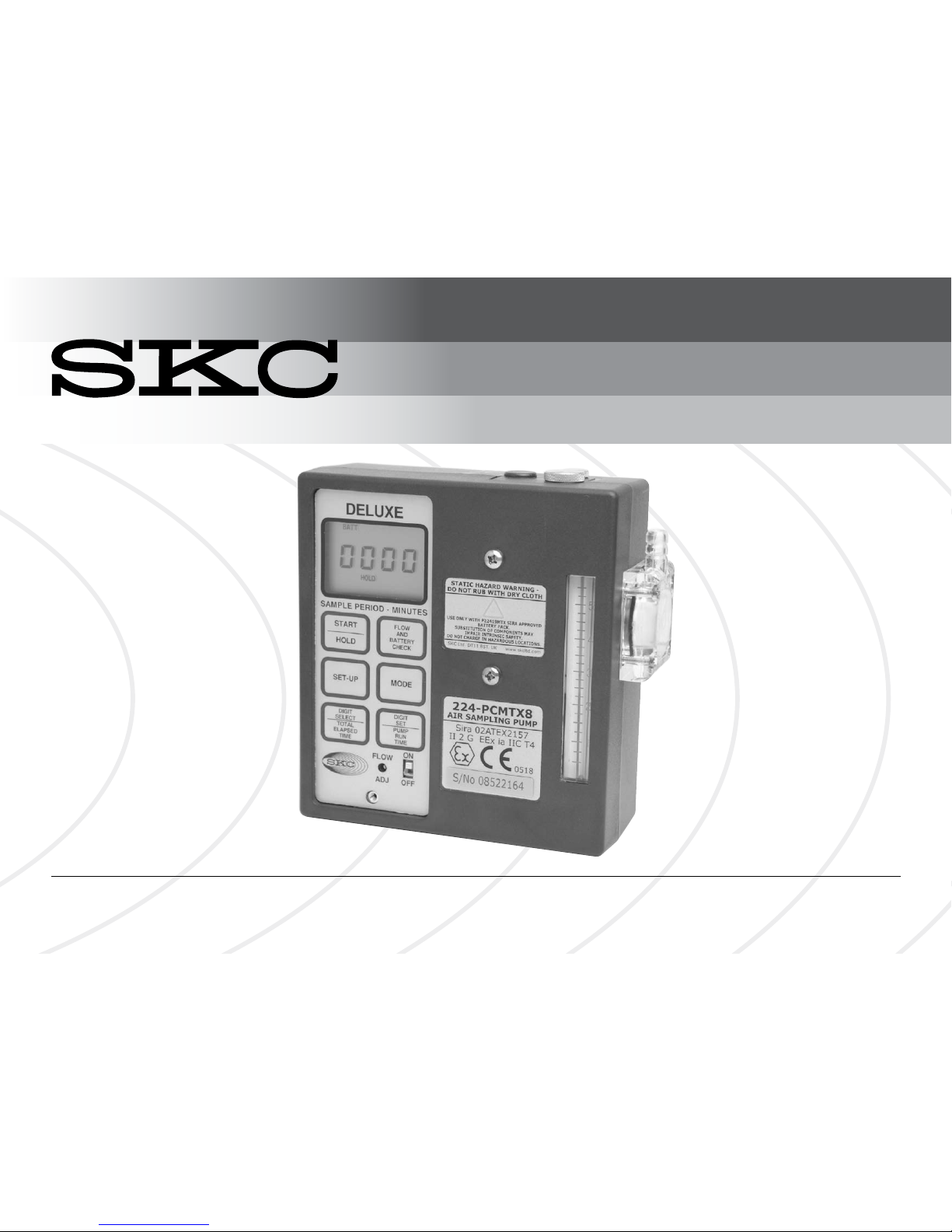
1) Pump Models
224-44MTX Standard pump with simple on/off control.
224-PCMTX4 Intermediate pump with on/off control, sample hold and elapsed run time display.
224-PCMTX8 Deluxe pump with full timer control and timer display.
2) Care of Universal MTX Series Pumps
• Always use the correct SKC batteries and battery chargers designated for the Universal MTX series pumps.
• Never run the pump long term without a tube or filter medium in place.
• When carrying out sampling using long term colour change tubes always use a tandem tube holder with trap
tube. This will prevent the aggressive fumes generated by these tubes from entering and damaging the pump
mechanism.
• When carrying out sampling using impingers always fit a trap between the impinger and pump inlet. This will
prevent the possibility of the fluid used in the impinger from entering and damaging the pump mechanism. As a
further precaution always ensure that the pump flow rate is set to below 1 litre/min before connecting the trap and
impinger to the pump inlet. For stability use the accessory mounting screws (refer to pump diagram on pages 10
and 11) to fix the impinger bracket to the front of the pump.
• The Universal MTX series pump cases are IP20 rated, they are not rated as water or splashproof and therefore
must not be used where it is possible for water to enter the pump casing.
• Universal MTX series pumps are fitted with a particulate filter which is easy to replace. For general maintenance
replace the filter every 2-3 months or if it appears dirty. New filters are white in colour (order Part No. P2240901).
Warning - Failure to follow these guidelines will void the product warranty.
General Information

www.skcltd.com 224-UMTXM Issue K Page 9
General Information
3) Non ATEX Certified Variants of the Universal Pump
The Universal pumps are also produced in a variant range which is UL certified for intrinsic safety and these pumps
are therefore not suitable for use in potentially explosive atmospheres in Europe where ATEX approval is mandatory.
Pump components vary between the UL and ATEX certified variants, therefore components must not be interchanged
between these pumps. If in any doubt please contact SKC Ltd customer services for advice.
4) Sampling Methods
This instruction manual provides the necessary information to set up and operate the Universal MTX series pumps. For
more detailed information on specific sampling methods please refer to SKC’s Step-By-Step Guide to Air Sampling
(Part No. 224-G1). To obtain a free copy please contact SKC Ltd customer services on +44 (0) 1258 480188 or
download at www.skcltd.com.
5) The WEEE Directive
This product is marked with the crossed out wheelie bin symbol, which identifies that it falls within the
scope of the EC Directive 2002/96/EC on waste electrical and electronic equipment (WEEE). At the end of
it’s useful life, this product must be disposed of in an environmentally sound way as detailed in the Directive.
Note that the battery pack must be separated from the pump and disposed of as detailed in the Batteries
Directive (see below). Please contact your local distributor or SKC Ltd for further details on how to comply
with the requirements of the WEEE Directive. SKC Ltd’s producer registration number is WEE/KH0054TQ.
6) The Batteries Directive
The NiMH battery pack supplied with this pump and any spare battery packs purchased for it, fall within the scope of
the EC Directive 2006/66/EC on batteries and accumulators and waste batteries and accumulators. At the end of the
battery pack’s life it must be disposed of in an environmentally sound way as detailed in the Directive. Please contact
your local distributor or SKC Ltd for further details on how to comply with the requirements of the Batteries Directive.
SKC Ltd’s batteries producer registration number is BPRN00454.
Page 10 224-UMTXM Issue K www.skcltd.com
20 19
18
17
16
15
14
13
12
11
109
8
7
6
5
4
3
2
1
21
20
22
23 24 25
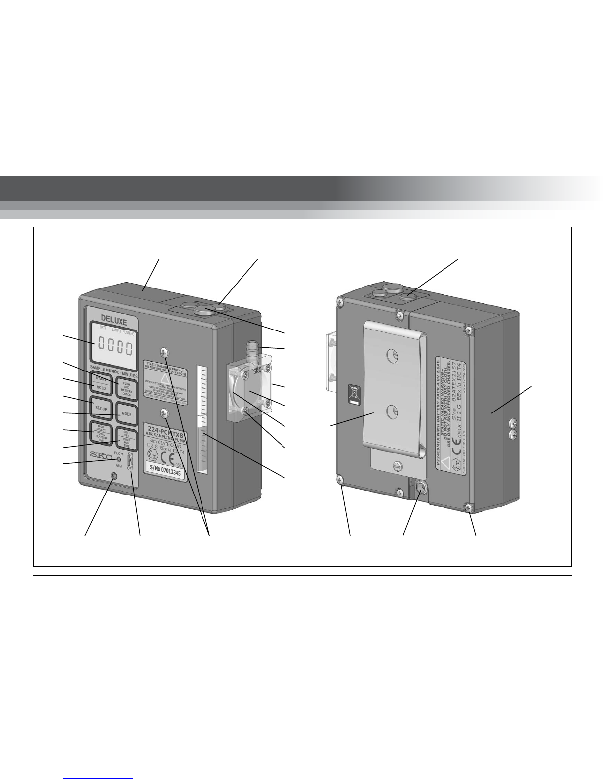
Diagram of the Universal MTX Pump

www.skcltd.com 224-UMTXM Issue K Page 11
Key to Pump Diagram
1. LCD screen
2. Flow and battery check key
3. START / HOLD key
4. SET-UP key
5. MODE key
6. SELECT key
7. SET key
8. Flow adjust control screw
9. Anti-tamper cover retaining screw
10. On/off switch
11. Accessory mounting screws
12. Flow indicator
13. Filter housing screws (4qty)
14. Filter O ring seal
15. Inlet protection filter
16. Inlet protection filter housing
17. Air inlet
18. Exhaust port cover
19. Low flow mode screw cover
20. Battery pack
21. Low flow mode regulator cover
22. Belt clip
23. Main case screws (4qty)
24. Battery pack charging jack socket
25. Battery pack screws (2qty)
Page 12 224-UMTXM Issue K www.skcltd.com
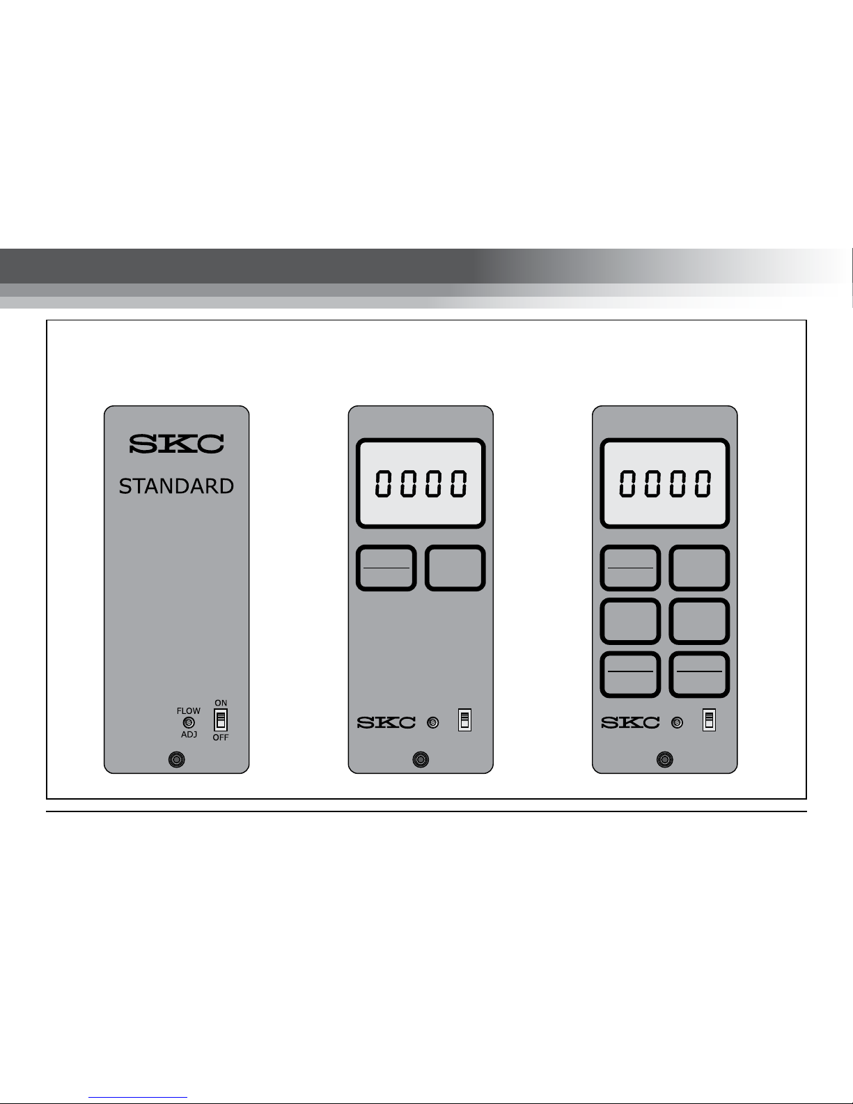
DELUXE
SAMPLE PERIOD - MINUTES
START
HOLD
SET-UP
DIGIT
SELECT
TOTAL
ELAPSED
TIME
FLOW
AND
BATTERY
CHECK
MODE
DIGIT
SET
PUMP
RUN
TIME
ON
OFF
FLOW
ADJ
INTERMEDIATE
SAMPLE PERIOD - MINUTES
START
HOLD
FLOW
AND
BATTERY
CHECK
ON
OFF
FLOW
ADJ
BATT SAMPLE RUNNING BATT SAMPLE RUNNING
Standard Control
Panel : 224-44MTX
Intermediate Control
Panel : 224-PCMTX4
Deluxe Control
Panel : 224-PCMTX8
Pump Controls Layout

www.skcltd.com 224-UMTXM Issue K Page 13
APPLICABLE TO ALL MODELS
1) Charging the Battery Pack
Prior to first use the battery pack should be fully charged, ideally overnight.
The Universal MTX series pumps must only be charged using the correct SKC chargers (Part Nos. 223-203A
- single charger, 223-103A - five station charger).
The charger is supplied with mains input plugs suitable for use in the UK, Europe, USA and Australia / New
Zealand. Select the correct mains input plug and fit it to the charger.
Plug the charger output jack plug into the mating socket at the rear of the battery pack. Plug the charger into
the electrical mains supply and switch on the power. The LED indicator on the charger will illuminate to indicate
that the charger is charging at full rate.
After 16 hours the charger will automatically switch to trickle charge, identified by the LED indicator on the
charger flashing on and off.
When fully charged disconnect the charger jack plug from the battery pack.
2) Accessing the Controls
To access the controls unfasten the screw retaining the anti-tamper control cover (No. 9) using the large bladed
screwdriver attachment of the supplied toolkit, and remove the cover to access the controls.
3) On/Off Switch (No. 10)
Set the on/off switch to the ON position and the pump will start to run. On Models 224-PCMTX4 & 224-PCMTX8,
the LCD screen will activate, and show the legends BATT, SAMPLE RUNNING and four zeros. If left running
the timer display will increment in one minute steps up to a maximum of 9999 minutes (approximately one
week), at which point the timer display will revert to 0000 minutes and continue to increment.
Getting Started

Page 14 224-UMTXM Issue K www.skcltd.com
Getting Started
4) Flow Adjust Screw (No. 8)
Use the small bladed screwdriver attachment of the supplied toolkit to turn the flow adjust screw. To increase
the flow rate turn clockwise. The span of the flow adjust screw is 12 turns. DO NOT FORCE the flow adjust
screw, and ensure the screwdriver end is securely located in the adjust screw slot.
Use a suitable calibrated flowmeter (such as a chek-mate or rotameter) to set the required flow rate, do not
use the built in flow indicator.
APPLICABLE TO MODELS 224-PCMTX4 & 224-PCMTX8 ONLY
5) START/HOLD Key (No. 3)
Once the pump has been switched on using the on/off switch, press the START/HOLD key to put the pump
into hold mode. The pump will stop running and the timer display will freeze. The legend HOLD is indicated
in the bottom left of the LCD screen. Press the START/HOLD key again to restart the pump and the timer will
continue to increase from the point at which it was frozen. The words SAMPLE RUNNING will appear in the top
right of the LCD screen. Subsequent pressing of this key will toggle between sample running and hold modes.
6) FLOW AND BATTERY CHECK Key (No. 2)
With the pump in hold mode, press the FLOW AND BATTERY CHECK key. The pump will start to run but the
timer will remain frozen at its current reading. The legend HOLD in the bottom left of the LCD screen will flash
on and off to indicate that the pump is in the flow and battery check mode. Flow checks can now be carried
out without the time taken being included on the timer display.
If the pump battery is fully charged the legend BATT OK is displayed. If the battery is flat the legend LO BATT
is displayed.
Press the FLOW AND BATTERY CHECK again to return the pump to hold mode.

www.skcltd.com 224-UMTXM Issue K Page 15
Getting Started
APPLICABLE TO MODEL 224-PCMTX8 ONLY
7) SET-UP Key (No. 4)
With the pump in hold mode, press the SET-UP key to enter setup mode. The LCD screen will show the legend
SET UP DELAYED START and the right hand digit will flash.
In the setup mode the delayed start time, sample time and run time can be entered.
8) MODE Key (No. 5)
With the pump in the setup mode press the MODE key to sequence through the DELAYED START, SAMPLE
PERIOD and PUMP PERIOD settings, indicated by the corresponding legends on the LCD screen. The function
of these three settings is explained in the section ‘Operating the Timer’ on pages 16 to 19.
The required values for these three settings can be entered using the DIGIT SELECT and DIGIT SET keys.
9) DIGIT SELECT key (No. 6)
With the pump in the setup mode and the required time setting selected, press the DIGIT SET key to cycle
through the four timer digits on the display. The currently selected digit is indicated by flashing on and off. When
the required digit is selected it can be set to the required value using the DIGIT SET key.
10) DIGIT SET key (No. 7)
With the pump in the setup mode, the required time setting selected and the required digit selected, press the
DIGIT SET key to increment the value of the digit from 0 to 9 and back to 0.

Page 16 224-UMTXM Issue K www.skcltd.com
Operating the Timer (224-PCMTX8 Only)
The timer function features three settings used to achieve the various modes of operation:
1. DELAYED START - The time period in minutes that will elapse prior to the pump starting to run. Setting
this value to zero disables the delayed start function.
2. SAMPLE PERIOD - The time period over which sampling will occur. Works in conjunction with the PUMP
PERIOD. Setting this value to zero will disable the timed run function and the pump will run continuously
until stopped using the START/HOLD key.
3. PUMP PERIOD - The time period in minutes during which the pump is actually running. If the PUMP
PERIOD is set the same or to a higher value than the SAMPLE PERIOD, the pump will run continuously
for the duration of the SAMPLE PERIOD. If the PUMP PERIOD is set to a lower value than the SAMPLE
PERIOD then the pump will automatically calculate on and off periods to apportion the required PUMP
PERIOD time over whole of the SAMPLE PERIOD time.
Setting a Simple Timed Run
Example: 8 hour timed run with no delayed start.
1. Switch the pump on and press the START/HOLD key to enter hold mode.
2. Press the SET-UP key to enter setup mode.
3. Press the MODE key to cycle to the SAMPLE PERIOD setting option. The right hand digit will be flashing.
4. The timer is set in minute values. Calculate the required sample period in minutes - 8 hours = 480 minutes.
Thefore the right hand digit should be set to 0.
5. Press the DIGIT SELECT key to select the second digit from the right.
6. Press the DIGIT SET key to increment the digit to 8.

www.skcltd.com 224-UMTXM Issue K Page 17
Operating the Timer (224-PCMTX8 Only)
7. Press the DIGIT SELECT key to select the third digit from the right.
8. Press the DIGIT SET key to increment the digit to 4. The digits should now read 0480.
9. Note that if a SAMPLE PERIOD time is entered, but the PUMP PERIOD is left at 0000, the pump will run
continuously for the duration of the SAMPLE PERIOD.
10. The pump is now set up to run for 8 hours and switch off. To start the timed run press the START/HOLD
key. The pump will start and the legend SAMPLE PERIOD will flash on and off in the top right of the LCD
screen. At the end of the 8 hours (480 minutes) the pump will automatically stop and the display will show
the legends HOLD and SAMPLE OVER, and the elapsed run time. Should the pump prematurely stop
during the sample period the actual elapsed run time will be displayed.
Setting a Timed Run with Delayed Start
Example: 8 hour timed run with a 2 hour delayed start
1. Switch the pump on and press the START/HOLD key to enter hold mode.
2. Press the SET-UP key to enter setup mode.
3. The right hand digit of the START DELAY time will be flashing, the required start delay time in minutes can
now be entered. 2 hours = 120 minutes. Therefore leave the right hand digit set at 0.
4. Press the DIGIT SELECT key to select the second digit from the right.
5. Press the DIGIT SET key to increment the digit to 2.
6. Press the DIGIT SELECT key to select the third digit from the right.
7. Press the DIGIT SET key to increment the digit to 1.
8. The START DELAY time is now set to 120 minutes.

Page 18 224-UMTXM Issue K www.skcltd.com
Operating the Timer (224-PCMTX8 Only)
9. Press the MODE key to cycle to the SAMPLE PERIOD setting option. The right hand digit will be flashing.
10. The timer is set in minute values. Calculate the required sample period in minutes - 8 hours = 480 minutes.
Thefore the right hand digit should set to 0.
11. Press the DIGIT SELECT key to select the second digit from the right.
12. Press the DIGIT SET key to increment the digit to 8.
13. Press the DIGIT SELECT key to select the third digit from the right.
14. Press the DIGIT SET key to increment the digit to 4. The digits should now read 0480.
15. Note that if a SAMPLE PERIOD time is entered, but the PUMP PERIOD is left at 0000, the pump will run
continuously for the duration of the SAMPLE PERIOD.
16. The pump is now set to start after a delay of 2 hours, run for 8 hours and then switch off. To start the
timed run press the START/HOLD key. The LCD screen will show the legend DELAYED START flashing in
the bottom left of the screen and the start delay time will count down from 120 minutes. At the end of the
start delay the pump will automatically start and the legend SAMPLE PERIOD will flash on and off in the
top right of the LCD screen. At the end of the 8 hours (480 minutes) the pump will automatically stop and
the display will show the legends HOLD and SAMPLE OVER, and the elapsed run time. Should the pump
prematurely stop during the sample period the actual elapsed run time will be displayed.
Setting an Intermittent Sample
Intermittent sampling allows a sample to be taken over a period of up to 9999 minutes (approximately one
week) and can prove extremely useful for environmental or ambient monitoring. To sample over a period of one
week and produce an average measurement, the pump is set to actually draw air for a period that the battery
can handle such as 8 hours over the 7 day period.
This manual suits for next models
2
Table of contents
Other SKC Water Pump manuals


SKC
SKC 220 Series User manual

SKC
SKC Vac-U-Go 228-9605 User manual

SKC
SKC 224-PCXR4 User manual

SKC
SKC TOUCH Operating instructions

SKC
SKC AirChek 220-3100 User manual

SKC
SKC Pocket Pump TOUCH User manual

SKC
SKC Flite 2 User manual

SKC
SKC AirChek 52 User manual

SKC
SKC AirChek 3000 User manual

SKC
SKC AirChek XR5000 User manual


Popular Water Pump manuals by other brands


Dover
Dover WILDEN PRO-FLO P1 Series Engineering, operation & maintenance

AxFlow
AxFlow Aturia ND Series Operation & maintenance manual

Crane
Crane Barnes PS Omni Grind Plus OGP2022CO Series installation manual

Kripsol
Kripsol ARTIK Series user manual

Grundfos
Grundfos KPC Installation and operating instructions

Alemite
Alemite 7785 Series Service guide