GASDNA DA-50 User manual
June 12, 2012
Page 1 out of 14
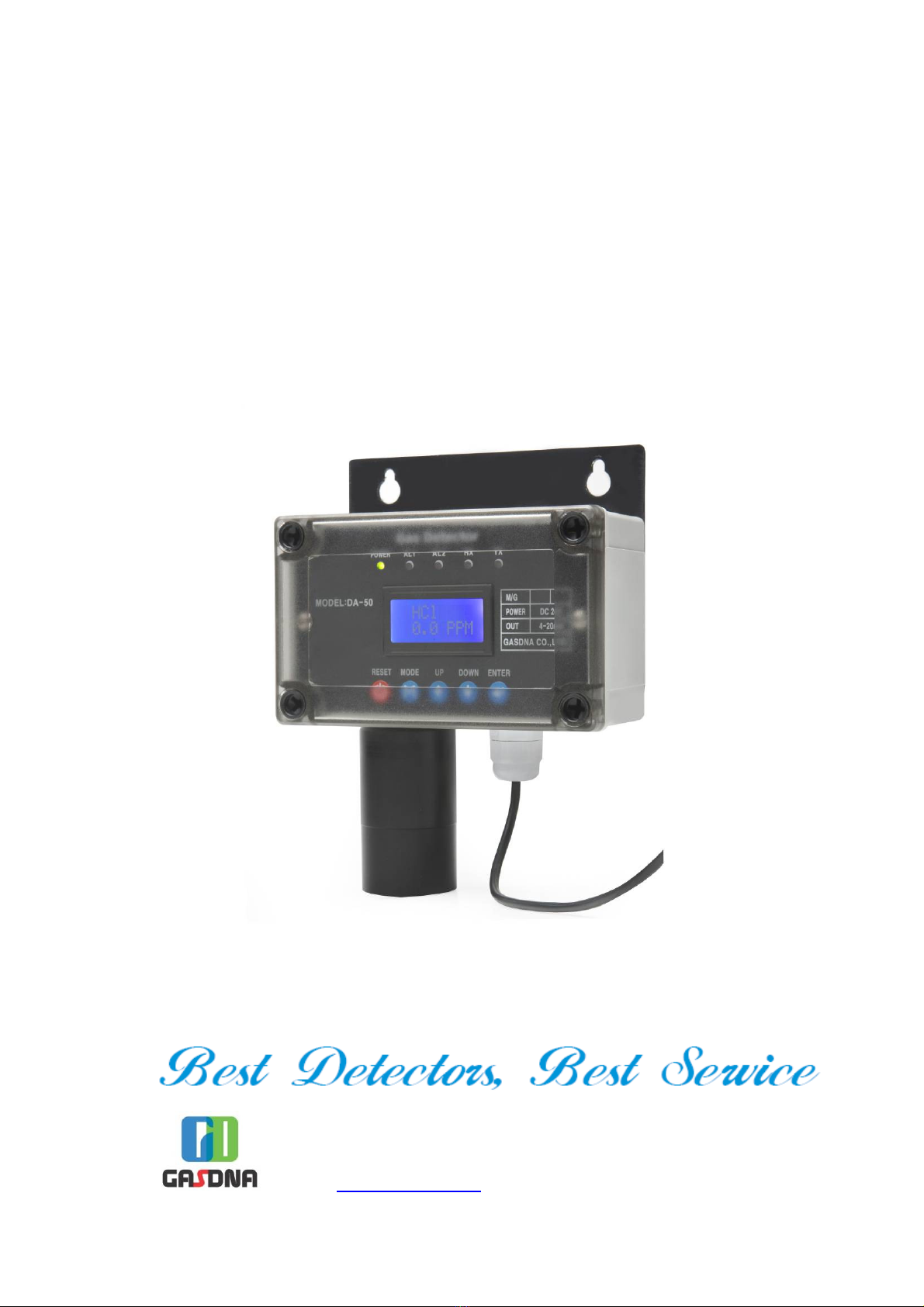
SMART Gas Detector
/Transmitter(4~20mA)
with built-in CD
DA-50
C-910C, Bupyeong Woolim ion’s Valley,
#425, Cheongcheon-Dong, Bupyeong-Gu, Incheon, Korea
TE : +82-32-623-7507 FAX: +82-32-623-7510
E-mail: sales@gasdna.com | Web: www.gasdna.com

June 12, 2012
Page 2 out of 14
Contents
▣ Introduction ------------------------------------------------------------------------- 3
▣ Features ----------------------------------------------------------------------------- 3
▣ Specification ------------------------------------------------------------------------ 4
▣ Operation keys --------------------------------------------------------------------- 5
▣ Sensor ca ibration -------------------------------------------------------------- 6 ~ 7
▣ Sensor rep acement ------------------------------------------------------------- 7
▣ Wiring -------------------------------------------------------------------------------- 8
▣ Dimension -------------------------------------------------------------------------- 8
▣ Insta ation -------------------------------------------------------------------------- 9
▣ Programming ------------------------------------------------------------------ 10 ~14

June 12, 2012
Page 3 out of 14
[Introduction]
DA-50 detects various combustib e & toxic gases eaked from industria areas for gas producers, gas
users, gas reservoirs, gas by-producers, and so on, in order to prevent any accidents in advance.
DA-50 converts digita signa into the 4-20
㎃
standard current signa for output signa which can be
transmitted to various externa devices such as PLC, DDC, RECODER, and so on. Using these functions,
you can easi y construct the gas monitoring system more extensive as we as more comprehensive.
DA-50 provides RS-485 communication signa and gas eakage a arm signa by re ay contact output.
Besides, DA-50 has DC 4-20mA standard output which rea izes max 2500m ong distance output signa
transmission from sensor to receiver and RS-485 communication signa which rea izes max 1000m ong
distance signa transmission.
[Features]
◈
Digita Process
Digita process based on bui t-in micro processor rea izes various artificia inte igent functions which
resu t in more convenient, more accurate, and more efficient gas detection environment.
◈
Po ycarbonate Housing
Po ycarbonate housing which has corrosion proof materia and water proof structure is the best
app ication to detect corrosive gas.
◈
Se f Diagnosis
Digita processor automatica y diagnoses the sensor signa and sends 2mA error signa output on the
ma function in the sensor.
◈
LCD disp ay with Back Light
LCD offers rea -time disp ay of gas density and back ight offers easy reading even in dark area.
◈
User Programmab e Menu
User programmab e ca ibration density and detection rage offers user’s own operating functions.
◈
Mu ti Signa Output
Various output signa s - DC 4-20mA, 2 step-re ay contact, & RS-485(option) – provides best networking
with a kinds of devices & equipments.

June 12, 2012
Page 4 out of 14
◈
4-20mA Transmitter
4-20mA output enab es stab e and ong distance (maximum 2.5km) signa transmission.
◈
RS-485
RS-485 enab es stab es stab e and ong distance (maximum 1.2km) signa communication.
◈
A arm output
SPST 2 step re ay contacts (AL1/AL2).
[Specification]
Detection princip e Cata ytic, e ectro-chemica , NDIR, or PID
Gas samp ing Diffusion
Target gas Refer to the ist
Density indication
LCD disp ay - PPM, %LEL, or %
Response time Within 20 seconds, 90% / fu sca e
Accuracy ≤ ±2% / fu sca e
Sensor ca ibration Ca ibration with switch
Sensor para ax Zero – ≤ ±1% / 6 months, Span -≤ ±1% / 6 months
User programmab e Ca ibration density, detection range
Input power DC 20 ~ 30V
Output power 4 ~ 20mA / fu sca e – maximum 2.5km ong signa transmission
Communication RS-485 – maximum 1.2km ong signa transmission
with GasDNA’s own protoco
Operating temperature and
humidity -20
℃
~50
℃
, 5~95% RH (non-condensing)
Signa wire CVVS & CVVSB 1.25sq x 3 wires - shie d type
A arm re ease Manua or Automatic
Mounting Wa or pipe mounting
Housing Po ycarbonate
A arm output 2 step- re ay contacts (AL1/AL2)
June 12, 2012
Page 5 out of 14
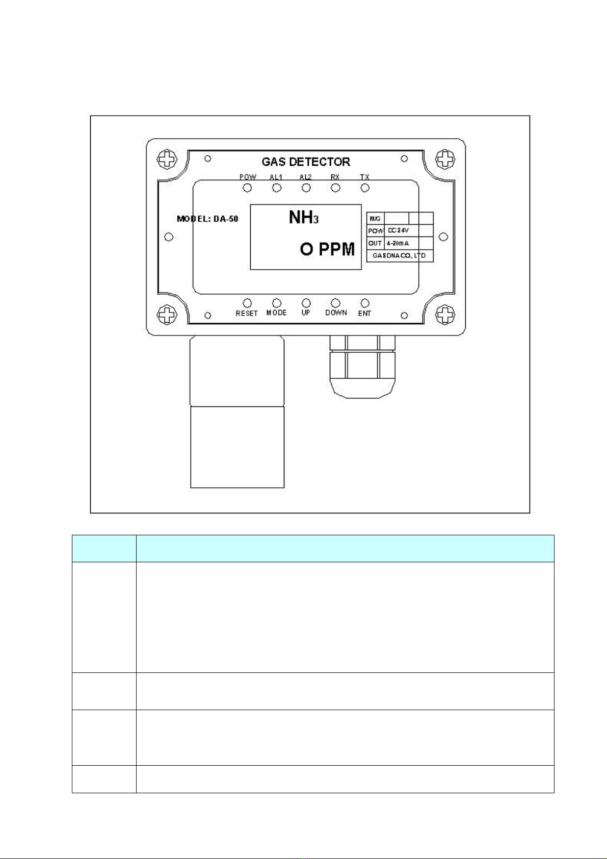
[Operation Keys]
Keys Description
RESET
Re ease the a arm re ay.
- When AL1 or AL2 re ay operates, you can re ease it (In manua mode)
(ex) If you set manua mode in AL-RESET menu,
(1) When the measured va ue is ower than AL1 va ue, AL1 re ay off.
(2) When the measured va ue is higher than AL1 va ue, AL1 re ay on.
MODE
- Enter into setting mode from measuring mode.
- In setting menu, move to other setting menus.
UP
Increase the setting va ue
- When you keep touching it more than 5 seconds, the setting va ue increase very
fast.
DOWN Decrease the setting va ue

June 12, 2012
Page 6 out of 14
- When you keep touching it more than 5 seconds, the setting va ue decrease very
fast.
ENT Restore the set va ue
POW Power on.
A 1 AL1 operates.
A 2 AL2 operates.
RX RS-485 receives signa .
TX RS-485 sends signa .
[Sensor Calibration]
Gas sensor’s property is subject to change whi e it is being used. This is common to a sensors. You
have to ca ibrate the sensor periodica y to keep the optimum condition of sensor.
DA-50 has automatic ca ibration function by micro processor.
1. Zero calibration
P ease fo ow be ow process to zero-ca ibrate sensor output.
①
P ease keep touching the MODE key more than 2 seconds through g ass window and enter
into setting mode.
②
Then, LCD shows “CAL-[ZERO]”. P ease touch ENT key.
③
Then, LCD shows “ZERO GAS”. P ease infuse the standard gas.
④
When the measured va ue gets stab e, p ease touch ENT key.
⑤
Then, if zero ca ibration is successfu , LCD shows “[OK]”.
▲ Caution: For zero ca ibration, you shou d have c ean status without any gases. If you cannot have
c ean status, p ease use nitrogen gas for zero ca ibration.
2. Span calibration
P ease fo ow be ow process using standard gas to ca ibrate the inear change of sensor output.
①
P ease assemb e ca ibration nipp e on sensor cap.
②
Then, p ease touch MODE key more than 2 seconds after disassemb ing main cover. It eads
you to setting mode.
③
Then, p ease move to “CAL [SPAN]” menu and touch ENT key.
④
Then, LCD shows “SPAN-ADJ”. P ease input desired ca ibration gas density va ues touching
UP & DOWN keys. When you finish it, p ease touch ENT key. (gas density set finished)
⑤
Then, LCD shows “SPAN-GAS”. Then, p ease infuse the ca ibration standard gas. Whi e you
infuse the gas, LCD va ues approaches the va ues of gas density. When the LCD shows stab e
gas va ues, p ease touch ENT key. (span ca ibration finished).

June 12, 2012
Page 7 out of 14
⑥
Then, p ease stop infusing the gas and dissemb e the ca ibration nipp e whi e LCD va ues gets
ess and shows “Ho ding PPM” fina y.
⑦
After 3 minutes when an LCD va ue gets ess than 9 PPM, it automatica y enters into measuring
mode. (Or when LCD va ue gets ess than 9 PPM, you can touch RESET key to enter into
measuring mode)
▲ Caution: Span ca ibration gas shou d be ranged from 5ppm to 90ppm. Sensor ca ibration is not
possib e with high density gas. High density gas puts excessive burden to the sensor and it damages
the sensor or reduces the sensor ife time extreme y.
▲ Caution: For calibration after sensor replacement, please wait 10 minutes from power on.
[Sensor Replacement]
DA-50 has sensor cap & sensor fi ter in order to protect sensor. This sensor cap composes of two
modu es for easy disassemb y. P ease fo ow be ow steps for sensor rep acement.
①
P ease make sure of power off to DA-50.
②
P ease open the cover of DA-50.
③
P ease unscrew the two bo ts fixing the disp ay board and disassemb e the disp ay board.
④
P ease disassemb e the 3 wire connector which connects the sensor and sensor board.
⑤
P ease rotate the sensor cap counterc ockwise and detach the sensor cap.
⑥
P ease rotate new sensor cap c ockwise and fix it.
⑦
P ease connect the 3 wire connector between sensor and sensor board.
⑧
P ease fix the disp ay board screwing the two bo ts.
⑨
P ease fix the four nuts on the cover of DA-50
⑩
P ease power on.
⑪
P ease do sensor ca ibration.
⑫
After sensor ca ibration, measuring mode automatica y starts.
▲ Caution
P ease make sure of power off to DA-50 before sensor rep acement or disp ay board
disassemb y.
If the direction of sensor cab e connector is different with sensor board connector socket, both
can not be assemb ed.
P ease fix the sensor cap and main cover tight y to keep water proof structure.

June 12, 2012
Page 8 out of 14
[Wiring]
Detector Indicator
[Dimension]

June 12, 2012
Page 9 out of 14
[Installation]
1. Place
1) Horizonta : C ose to the high y suspected p ace for gas eakage, such as gas va ve and connection of
gas pipe considering weight and stay of gas.
2) Vertica : Considering the specific gravity of target gas (air = 1),
▷
Light gas (specific gravity is ess than 1): P ease insta the sensor 20 – 30cm from cei ing in c osed
room. If it is open area, p ease insta the sensor high and c osest as possib e to the suspected point
for gas eakage.
▷
Weight gas (specific gravity is more than 1): P ease insta the sensor 20 – 30cm from the f oor. If it is
open area, p ease insta the sensor ow and c osest as possib e to the suspected point for gas
eakage.
2. Cautions
1) P ease avoid vibrating or physica impacting p ace. Vibration or physica impact can affect the output
va ue.
2) P ease avoid the high temperate or humid p ace. High temperate or humidity can resu t in ma function.
3) P ease avoid e ectronic noise area which has high frequency or high vo tage such as motor, pump, or
high vo tage power cab e.
4) P ease secure enough space for convenient maintenance. As DA-50 needs periodica maintenance
and ca ibration, you have to avoid inconvenient p ace for these jobs. Otherwise, we recommend
suction type detector.
5) Cab e
We recommend shie d type cab e to prevent externa noise and cab e duct, conduit pipe, or f exib e to
prevent externa impact. A so, p ease avoid the junctions between cab es. Otherwise, we recommend
junction box.
- Cab e specification and transmission distance
Transmission distance
0 ~ 500m 501 ~ 1,500m Over 1,500m
Cab e specification 0.75sq 1.25sq 2.0sq
In case of pressure-proof bui t-in cab e package, p ease choose the cab e with proper outer diameter fit in
inner size of package and tighten the cab e g and sufficient y in order to prevent any inf ow of gas or f ame.
June 12, 2012
Page 10 out of 14
MODE
DOWN
RESET MODE
RESET
RESET
UP
UP
UP
UP
UP
UP
DOWN
DOWN
DOWN
DOWN
DOWN
MODE
MODE
MODE
MODE
MODE
RESET
RESET
RESET
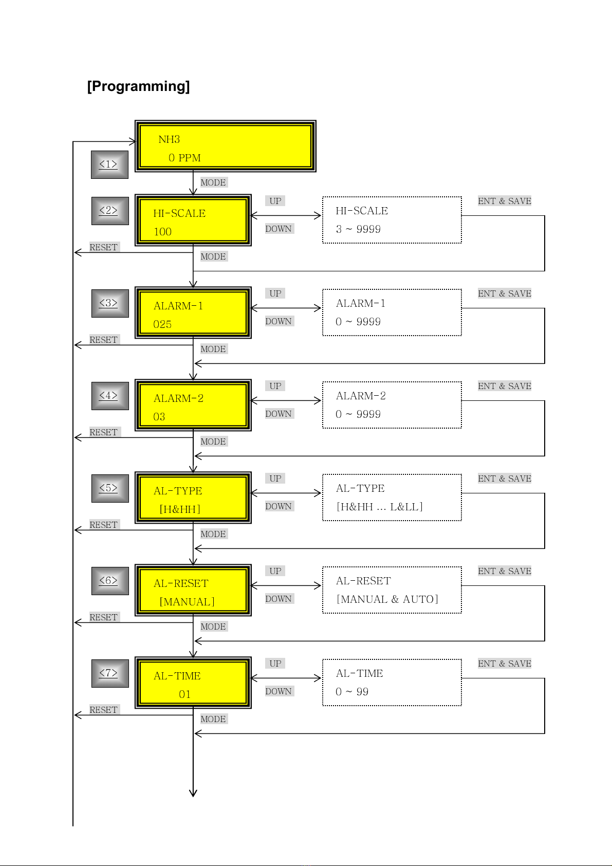
[Programming]
NH3
0 PPM
HI-SCALE
100
HI-SCALE
3 ~ 9999
ENT & SAVE
ALARM-1
025
ALARM-1
0 ~ 9999
ENT & SAVE
ALARM-2
03
ALARM-2
0 ~ 9999
ENT & SAVE
AL-TYPE
[H&HH]
AL-TYPE
[H&HH
…
L&LL]
ENT & SAVE
AL-RESET
[MANUAL]
AL-RESET
[MANUAL & AUTO]
ENT & SAVE
AL-TIME
01
AL-TIME
0 ~ 99
ENT & SAVE
<1>
<2>
<3>
<4>
<5>
<6>
< >
June 12, 2012
Page 11 out of 14
DOWN
RESET MODE
RESET
RESET
UP
UP
UP
DOWN
DOWN
MODE
MODE
MODE
ENT
ENT
RESET
UP
DOWN
MODE
RESET
OFFSET
000.0
OFFSET
000.0 ~ 050.0
ENT & SAVE
ADRRESS
01
ADRESS
0 ~ 99
ENT & SAVE
BAUDRATE
9600bps
BAUDRATE
[1200bps ~ 5 600bps]
ENT & SAVE
<9>
<10>
<11>
CAL
[ZERO]
ZERO GAS
0 PPM
ZERO GAS
[OK]
ZERO GAS
[FAIL]
<12> <12-1>
INITTIME
30
INITTIME
0~99
ENT & SAVE
<8>
June 12, 2012
Page 12 out of 14
UP
DOWN
MODE
ENT
ENT
RESET
RESET
RESET
RESET
ENT
<1> Measuring mode
- CD shows the gas density.
- If you touch MODE key during 2 seconds, you can enter into setting mode.
<2> HI-SCA E
- Full scale = 20mA
(ex) If you set HI-SCA E = 100,
4mA analogue output displays 0 .
12mA analogue output displays 50 .
CAL
[SPAN]
SPAN ADJ
050 PPM
SPAN ADJ
3 ~ 999 PPM
SPAN GAS
050 PPM
SPAN GAS
3 ~ 999 PPM
SPAN GAS
[OK]
SPAN GAS
[FAIL]
Holding
009 PPM
<13>
<13-1>
<13-2>
<13-3>

June 12, 2012
Page 13 out of 14
20mA analogue output displays 100 .
<3> A ARM-1
- Alarm-1 relay output (You can choose low or high by A -TYPE setting)
<4> A ARM-2
- Alarm-2 relay output (You can choose low or high by A -TYPE setting)
<5> A -TYPE(A ARM-TYPE)
- Four kinds alarm choices: H&HH, H& , &H, &
- Alarm relay: A ARM-1 and A ARM-2
ex) If you choose H&L,
ALARM-1: High a arm (it operates when measured va ue goes over the set va ue)
ALARM-2: Low a arm (it operates when measured va ue goes be ow set va ue)
<6> A -RESET(A ARM RESET)
- Choose Alarm release methods.
- AUTO
MANUA
(1) AUTO: Without touching RESET key, relay releases automatically when the
measured value goes out of alarm range.
(2) MANUA : With touching RESET key, relay can be released when the measured
value goes out of alarm range.
<7> A -TIME(A ARM TIME)
- Set time of temporary external impact or noise which affects the sensor’
’’
’s normal operation.
The detector skips the sensor’
’’
’s temporary abnormal operation during this time.
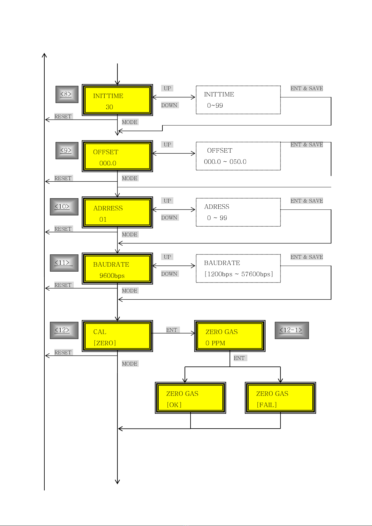
<8> INITTIME(initialization time)
- Set warming up time. Stable signal output is available after this time from power on.
<9> OFFSET
- Set values to offset the measurement error.
ex) If you set OFFSET = -5,
If sensor output = +5, LCD disp ays 0 after offset by -5.
<10> ADDRESS
- Set RS-485 address.
<11> BAUDRATE
- Set RS-485 baud rate.

June 12, 2012
Page 14 out of 14
<12> ZERO CA IBRATION
In CA [ZERO], when you touch ENT key, CD shows “ZERO GAS <0.0 PPM>” with random
value. Then, please infuse clean air or 100% nitrogen gas into sensor cap. Then, after the
CD value get stable, please touch ENT key. Then, CD shows “ [OK]”.
However, if the calibration is not successful, CD shows “[FAI ]” during 2 seconds.
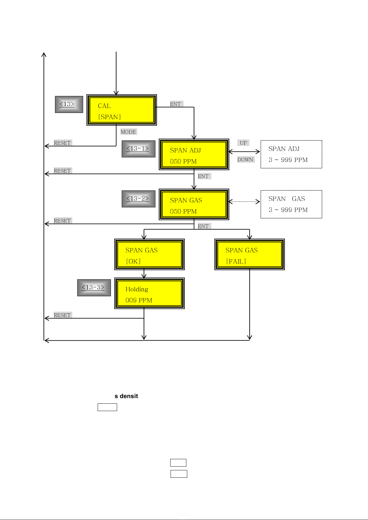
<13> SPAN CA IBRATION)
(ex) Target gas : H2S
Standard gas: H2S(25 PPM) + Air Balance
(1) In CA [SPAN], please touch ENT key.
(2) Please input H2S standard gas density value using UP & DOWN key. And then,
please touch ENT key)
(3) Please infuse H2S standard gas and wait until CD value gets stable. After the value
gets stable, please touch ENT key.
(4) When span calibration is successful, CD shows:
(5) Please eliminate the span gas from gas inlet and wait the CD value gets less than
10 PPM. When the CD value goes less than 10 PPM, measuring mode starts
automatically.
SPAN ADJ
025 PPM
SPAN GAS
025 PPM
SPAN GAS
[OK]
Holding
009
PPM
Table of contents
Other GASDNA Gas Detector manuals

Popular Gas Detector manuals by other brands

Critical Environment Technologies
Critical Environment Technologies CGAS-AP installation manual

Electronics
Electronics Ei413 quick start guide

Tecnocontrol
Tecnocontrol SE137EO user manual

Blackline Safety
Blackline Safety G7 BRIDGE user manual

Pro's Kit
Pro's Kit MT-4611 user manual

Tecnocontrol
Tecnocontrol SE192KM user manual


