10 | Page Rev 2-0 8/1/2018
Use the following chart to select the switch position for the desired
function:
To:
Set the Rotary Selector
Switch to:
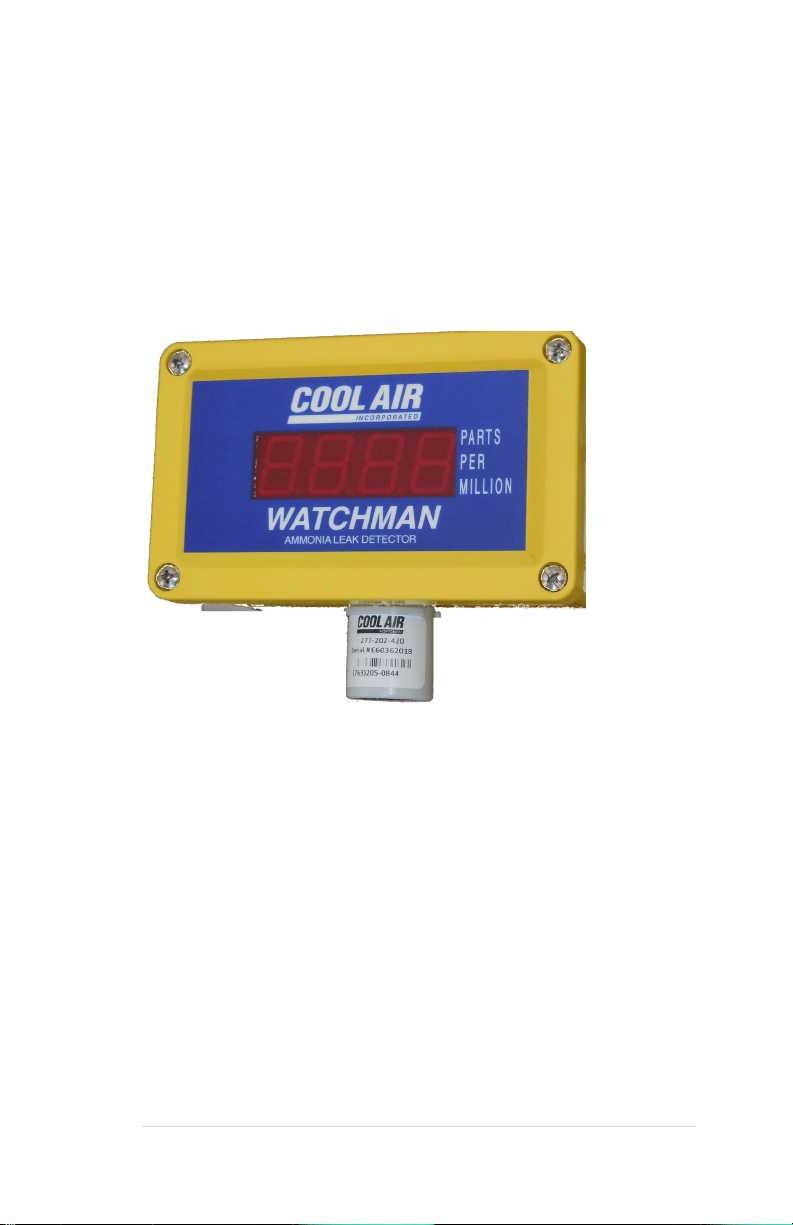
Display ammonia concentration in PPM
Display ammonia concentration in PPM
Display the firmware revision
Program the ammonia High alarm set point
Program the ammonia Low alarm set point
Display ammonia concentration in PPM (See Section Testing your system)
Display Electrochemical Sensor Zero offset
Note: If the rotary selector switch is left in a position other than “0”
without pushing an “UP” or “DOWN” button for more than 5
minutes, the digital display will begin to display ammonia
concentration. If this happens, return the selector switch to the “0”
position, then set the switch to the desired position. For example, if
you set the rotary selector switch to position “3” to program the
alarm set point, and if, after 5 minutes of inactivity the display
reverts to displaying ammonia concentration. Move the switch to
“0”, then back to “3” to continue programming the alarm set point.
Caution: Before closing the detector enclosure, be sure to
return the rotary selector switch to position “0” to
correctly display ammonia concentration.
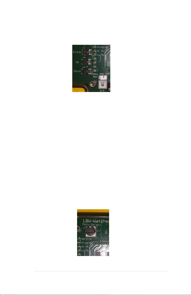
Additional functions are available through the rotary
selector switch when the detector is in program mode
(program LED on).
To:
Set the Rotary
Selector Switch to:
Display ammonia sensor temperature (Solid State Sensor Only)
Zero adjust for the Electrochemical sensor
Program the ammonia sensor 4 – 20mA Range
Set the Service Mode Time out
Set the Display start value. 0PPM, 10PPM, or 25PPM
Select for Solid State Sensor or Electrochemical Sensor