manuals.online logo
Brands
  1. Home
  2. •
  3. Brands
  4. •
  5. Tecnocontrol
  6. •
  7. Gas Detector
  8. •
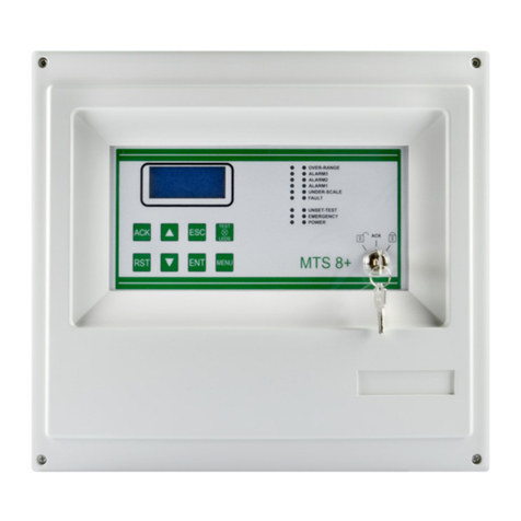
  9. Tecnocontrol SE192KM User manual

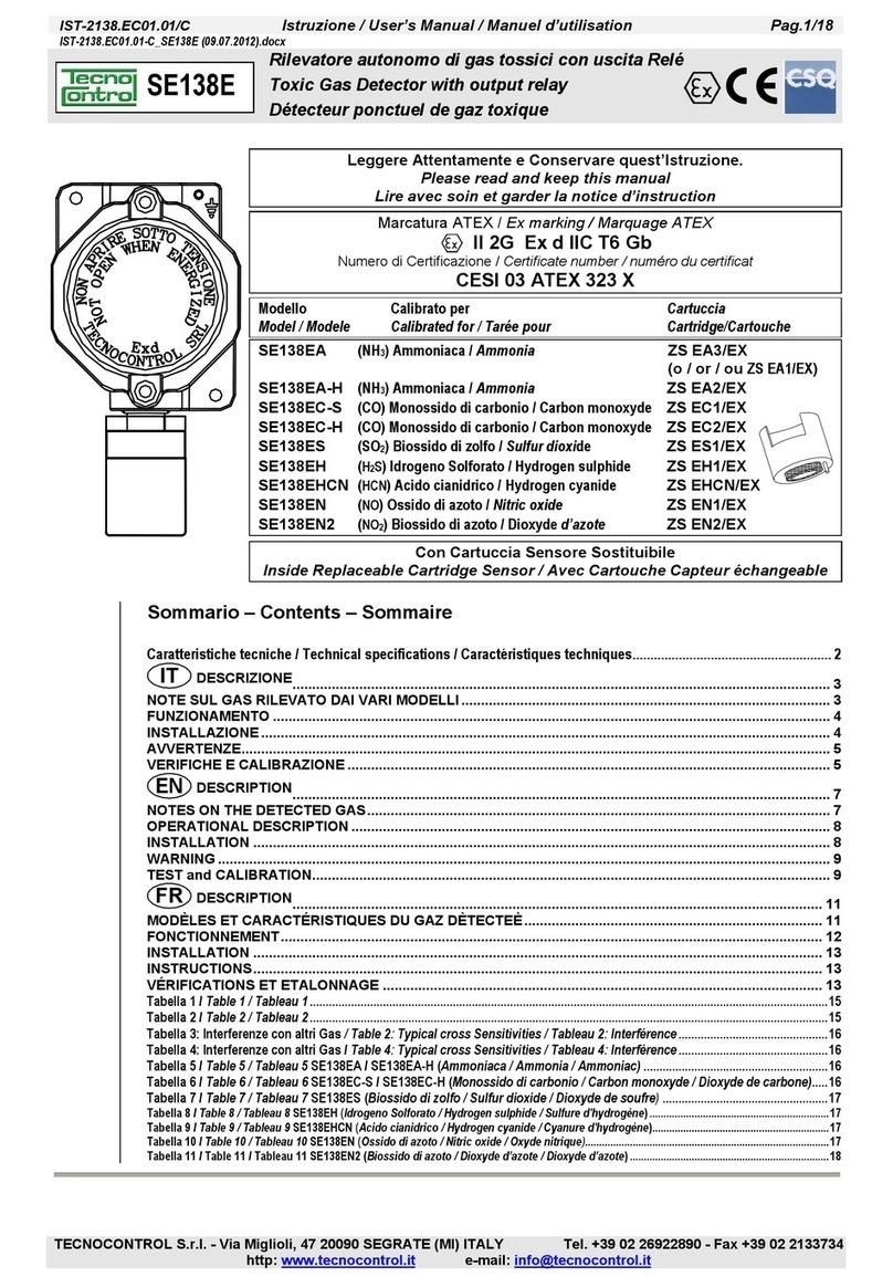
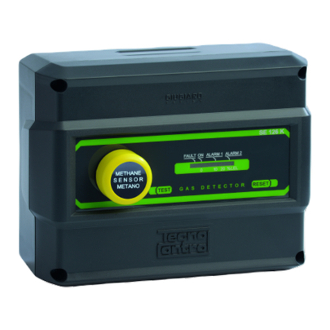
Tecnocontrol SE192KM User manual

IST-2148.KX01.01(I-SE128Kx)Istruzione / User’s Manual / Manuel d’utilisation Pag.1/1
Centralina gas per Centrali termiche con Sensore remoto
Gas detector for heating plants
Centrale détection de gaz pour chaufferies
TECNOCONTROL S.r.l. Via Miglioli 97 SEGRATE ( MI ) Tel: 02/26922890 Fax: 02/2133734
SE128K
Tecnocontrol SE148K
GAS DETECTOR RESET
%LEL
0
10
20
FAULT ON ALARM1 ALARM2
TEST
Sensori collegabili all’SE128K
Sensors which can be connected to the SE128K
Sondes raccordables au SE128K
Modello
Model
Modéle
Caratteristiche
Features
Caractéristiques
SE192KM Metano / Methane -IP44
SE192KG GPL / LPG -IP44
Caratteristiche tecniche / Technical specifications / Specifications techniques
Alimentazione con sensore / Power supply with sensor/ Alimentation avec
sonde 230Vac (-15/+10%) 50Hz / 4VA
Temp./umidità di funzionamento / Operation Temp./Humidity / Température et
humidité de fonctionnement -10 ÷ +50 °C / 5÷90 % r.h. 40°C
Temp./umidità di immagazzinamento / Storage Temp./Humidity / Température et
humidité de stockage -25 ÷ +55°C / 5÷95 % r.h.
Intervento allarme / Alarm intervention / Seuil d'intervention de alarme 10% LIE / LEL
Intervento blocco / Lock intervention / Seuil d'intervention de blocage 20% LIE / LEL
Contatti relè / Contacts rating / Contact relais 230Vac 3A SPDT
Dimensioni / Size / Dimensions 160 x 115 x 80 mm) / IP54
Sensore esterno / Remote sensor / Sonde extérieure Catalitico / Catalityc / Catalytiques
DESCRIZIONE
L'SE128K è una centralina per montaggio a
parete con un sensore remoto di tipo cataliti-
co per gas infiammabili. Possono essere
collegati sia i sensori tarati per Metano che
per GPL. Il grado di protezione dell'apparec-
chio è IP54. Sulla targa frontale è visibile la
barra Led che indica lo stato di funzionamen-
to e la concentrazione di gas rilevata dal sen-
sore. La centralinaè dotata di due livelli di
allarme con uscite a relè di tipo sigillato
normalmente eccitati con contatti in scam-
bio liberi da tensione. In Fig.1 è illustrato un
tipico collegamento da rete con sirena di al-
larmeedelettrovalvolanormalmentechiusa.
FUNZIONAMENTO
Quando la concentrazione di Gas raggiunge
il 10% del LIE, cui corrisponde l'accensione
del secondo Led rosso, interviene il primo
relè "ALARM1" che viene normalmente uti-
lizzato per comandare una sirena
(Mod.SE301A).
Quando la concentrazione di Gas rag-
giunge il 20%LIE si illumina il 3° Led
rosso e dopo 30 secondi si attiva il se-
condo relè "ALARM 2" per il blocco del
gas tramite elettrovalvola e/o l'interru-
zione dell'energia elettrica.
Quando la concentrazione di Gas rag-
giunge il 20%LIE si illumina il 3° Led
rosso e dopo 30 secondi si attiva il se-
condo relè "ALARM 2" che è
DESCRIPTION
The SE128K is a gas detector to be
wall-mounted. It is rated to IP54. It has
one remote catalytic sensor for flam-
able gases calibrated for Methane or
LPG.
On the front plate the LED bar shows
both the working condition and the gas
concentration detected by the sensor.
The instrument is supplied with two
alarm levels with sealed-type nor-
mally-activated relays outputs (ten-
sion-free change over contacts).
Fig. 1 shows a typical mains supply wir-
ing diagram with alarm siren and nor-
mally closed solenoid valve.
OPERATIONAL DESCRIPTION
When the gas concentration attains
10% LEL (illumination of the 2nd red
LED), the first "ALARM 1" relay will de-
activate.
This relay is normally used as a
prealarm for the controlling of a siren
(model SE301A).
When the Gas concentration attains
20% LEL, the 3rd red LED will illumi-
nate and after 30 seconds the second
"ALARM 2" relay will deactivate.
This relay is used for the gas cut-off
gas by means of a solenoid valve
and/or the interruption of the electric
energy)
DESCRIPTION
Le SE128K est une centrale de détection de
gaz pour montage aux mur et pouvant rece-
voir 1 sonde à distance de type catalytique
pour gaz inflammables, tarées pour le mé-
thane ou pour le GPL avec protection boîtier
IP65. L'indice de protection de la centrale est
IP54.
Sur la face avant de la centrale l'on distingue
le barregraphe indiquant l'état de fonction-
nement ainsi que la concentration de gaz
détectéeparlecapteur.
L'appareil est doté de 2 seuils d'alarme
avec sorties sur relais de type étanche
fonctionnant normalement excitée avec
contactsinverseurslibresdetension.
En figure1, un exemple de raccordement sur
secteur avec sirène d'alarme et électovanne
normalementouverts.
FONCTIONNEMENT
Lorsque la concentration de gaz rejoint 10%
de la LIE à laquelle correspond l'allumage de
la 2ème LED rouge, le 1er relais intervient en
se deséxcitant (ALARM1). Ce seuil est habi-
tuellement utilisé comme préalarme pour
commanderunesirène(SE301A).
Si la concentration augmente jusqu'à rejoin-
dre 20% de la LIE la 3ème LED s'allume, et
après une temporisation de 30 secondes la
LED rouge STOP s'allume et le relais se
deséxcitant(ALARM2).
IST-2128.KX01.01 Istruzione / User’s Manual / Manuel d’utilisation Pag.2/2
TECNOCONTROL S.r.l. Via Miglioli 97 SEGRATE ( MI ) Tel: 02/26922890 Fax: 02/2133734
utilizzato per il blocco del gas tramite
elettrovalvola e/o l'interruzione dell'e-
nergia elettrica.
Quando si attiva il relè "ALARM 2", si accen-
de il 4° Led rosso, il relè e la barra Led resta-
no attivati, fino a quando, eliminata la causa di
allarme, non viene premuto il pulsante
"RESET". Quest'ultimo, per sicurezza, non
intervieneseilsensorestarilevandogas.
Quando si verifica una situazione di guasto
del sensore, interviene il terzo relè "FAULT"
esiilluminailLedgiallo.
INSTALLAZIONE
Il Metano (CH4) è un gas più leggero dell'a-
ria, la sua densità relativa all'aria è 0,55, il suo
LIE (Limite inferiore di esplosività è 5%v/v (%
Volume).
Il GPL è un gas più pesante dell'aria formato
da una miscela composta dal 20-30% di
Propano (C3H8) e dall'80-70% di Butano
(C4H10). La densità relativa all'aria è 1,56 per il
Propano e 2 per il Butano, il LIE è 2,1%v/v
per il Propano e 1,5 %v/v per il Butano. Le
tarature per GPL sono normalmente effettua-
tecongasButano.
I sensori devono essere installati come de-
scritto nelle apposite istruzioni ad essi allega-
ti. Dopo l'installazione si deve applicare l'eti-
chetta autoadesiva inserita nella confezione
con il nome del gas di taratura confezione
con il tipo di gas indicato sull'etichetta di col-
laudodelsensoreremoto.
In Fig.3 sono indicate le dimensioni della
centralina che viene montata a parete
con tre tasselli.
In Fig.2 è illustrato lo schema di colle-
gamento da rete con la sirena ed elet-
trovalvola normalmente chiusa.
I morsetti sono di tipo ad innesto pola-
rizzati, si consiglia, di ancorare i cavi
nella custodia per evitare eccessive
sollecitazioni ai morsetti.
La distanza fra la centralina ed il senso-
re, non deve essere superiore a 100
metri utilizzando un cavo 3x1,5 mm2.
oppure non deve essere superiore a
200 metri utilizzando un cavo 3x2,5
mm2. Non è necessario utilizzare cavi
schermati.
La valvola di blocco gas, a riarmo ma-
nuale, va installata all'esterno del locale,
in posizione chiaramente segnalata e
protetta dalla pioggia diretta.
Guasti
In caso di guasto del sensore, errato
collegamento, interruzione o cortocircui-
to dei cavi tra centralina e sensore, si
diseccita il relè "FAULT", la segnalazio-
ne ottica a Led giallo "FAULT".
When the relay activates, the 4th red LED
illuminates. Both the relay and the LED bar
keep activating until the "RESET" button is
pushed after removing the cause of the
alarm. For security reasons, this button can-
not operate when the sensor is detecting
gas.
When a sensor fault occurs, the 3rd
"FAULT" relay deactivates and the yellow
LEDilluminates.
INSTALLATION
Methane (CH4) is a gas lighter than air. Its
density as to air is 0.55. Its LEL (Lower Ex-
plosivityLimit)is5%v/v(volume).
LPG is a gas heavier than air consisting of a
mixture of 20-30% Propane (C3H8) and 80-
70%Butane(C4H10).
Propane density as to air is 1.56 and its LEL
is 1.56%v/v . Butane density as to air is 2 and
its LEL is 2.1%v/v. GPL remote gas sensors
arenormallycalibratedwithButane.
The remote gas sensor must be installed
following instructions enclosed in its packag-
ing. After installation we advise to stick the
enclosed self-adhesive label that show the
calbrated gas written on the remote sensor
testlabel.
Fig. 3 shows the instrument size. It
should be wall-mounted by three screw
anchors.
Fig. 2 shows the AC powering connec-
tion with alarm siren and normally
closed solenoid valve.
The terminals are non reversible and
plug-in. Therefore the cables should be
anchored to the case in order to avoid
terminal overstress. The distance be-
tween the instrument and the sensor
must not exceed 100 meters using a
3x1.5 mm2cable, or 200 meters using a
3x2.5 mm2cable. It is not necessary to
use shielded cables.
The valve for the gas cut-off should be
installed outside the room in a clearly
indicated position and should be pro-
tected from rain.
Fault
In case of damaged sensor, wrong wir-
ing connection, interruption or cable
short circuit between the instrument and
the sensor, both the "FAULT" relay and
the optical indication of the yellow LED
"FAULT" will deactivate.
The "FAULT" relay, if necessary, can be
used both to signal remotely an occured
damage or to signal the absence of
power to the instrument.
The "FAULT" relay, is normally-
activated relays outputs (tension-
free change over contacts).
Ce seuil commande la coupure de l'énergie
électrique et par conséquence de l'électro-
vannenormalementouverts.
Dans ces conditions le barregraphe restera
illuminé et les relais désexcités jusqu'à ce
que l'on ait remédié aux causes de l'alarme
et réarmé ensuite le dispositif par action ma-
nuelle sur le bouton Cette action ne sera
possible que si la centrale à ce moment ne
détectepasdeprésencegazeuse.
Danslecasdedéfaillanced'uneouplusieurs
sonde, le relais de dérangement (FAULT)
interviendra simultanément à l'allumage de la
LED jaune de ou des voies se trouvant en
défaut.
INSTALLATION
Le méthane (CH4) est un gaz plus léger que
l'air. Sa densité par rapport à l'air est 0,55, sa
LIE (limite inférieure d'explosivité) est le
5%v/v(%volume).
Le GPL est en revenche un gaz plus
lourd que l'air, formé d'un mélange
composé de 20 à 30% pour le propane
(C3H8) et de 80 à 70% de butane
(C4H10).
La densité par rapport à l'air est de 1,56
pour le propane et de 2 pour le butane.
Sa limite inférieure d'explosivité est de
2,1%v/v pour le propane et 1,5%v/v
pour le butane. Les étalonnages pour le
GPL sont effectués normalment avec
du butane.
En figure 3sont indiquées les dimen-
sions de la centrale. La fixation s'éffec-
tue par des 3 vis et chevilles.
En figure 2 est illustré le schéma de
raccordement sur secteur 230vca, d'un
dispositif avec sirène et électrovanne
normalement fermée.
La distance entre la centrale et chaque
sonde ne doit pas être supérieure à 100
m en utilisant du cable 3 x 1,5mm2ou à
200 m en utilisant du cable 3 x 2,5mm2.
Il n'est pas nécessaire d'utiliser du cable
à écran.
Les borniers sont de type débrochable
et il est conseillé ceux-ci étant fixés afin
d'éviter une excessive tension mécani-
que sur les borniers.
L'électrovanne doit être installée à
l'extérieur du local, dans une posi-
tion ou à l'intérieur d'un boitier clai-
rement signalé et protégé de la
pluie et des projections de liquide.
Deteriorations
En cas de panne du capteur, erreur de
raccordement, court circuit ou coupûre
des cables entre la ou les sondes et la
centrale, le relais de dérangement s'ac-
tivera. La LED jaune s'illuminera sur la
ou les voies concernées.
IST-2128.KX01.01 Istruzione / User’s Manual / Manuel d’utilisation Pag.3/3
TECNOCONTROL S.r.l. Via Miglioli 97 SEGRATE ( MI ) Tel: 02/26922890 Fax: 02/2133734
Quest'ultimo, se richiesto, può essere
utilizzato per segnalare a distanza un
avvenuto guasto o la mancanza di ali-
mentazione alla centralina.
Il relè “FAULT” è normalmente eccitato
con contatti in scambio liberi da tensio-
ne.
Durante la fase di preriscaldo del sen-
sore, che è di circa 30 secondi, i relè di
allarme rimangono inibiti, mentre il Led
giallo e il relè "FAULT" vengono attivati.
Verifiche periodiche
Per verificare il funzionamento della
centralina premere il pulsante "TEST". Si
illuminerà la barra Led, si attiverà il relè
"ALARM1", dopo 30 secondi il relè
"ALARM2" e il 4° Led rosso. Per ripristi-
nare le condizioni di funzionamento
normale, premere il pulsante "RESET".
Si consiglia di effettuare la verifica di
funzionamento ogni 6-12 mesi.
Avvertenze
ATTENZIONE: il pulsante "TEST" si-
mula un situazione di allarme e pro-
voca il blocco dell'impianto.
AVVERTENZA IMPORTANTE: La
centralina non necessita di regola-
zioni dopo l'installazione. I trimmer di
taratura sigillati posti sul Circuito
Stampato non devono essere ma-
nomessi pena la perdita di ogni ga-
ranzia e il pericolo di rendere l'appa-
recchio non funzionante.
During the preliminary heating time of
the sensor (about 30 seconds), the
alarm relays are inhibited, while the yel-
low LEDs and the "FAULT" relay are
activated.
Periodical Testing
To check the instrument operation, push
the "TEST" button. The LED bar will illu-
minate and the "ALARM 1" relay will ac-
tivate. After 30 seconds the "ALARM 2"
relay and 4th red LED will activate. To
reset the normal working conditions,
push the "RESET" button.
Operation testing should be carried out
every 6/12 month.
Warnings
CAUTION: the "TEST" button simu-
lates an alarm condition and causes
the blockage of the plant.
VERY IMPORTANT WARNING: The
doesn't need adjustments after be-
ing installed. The sealed calibration
trimmers placed on the Printed Cir-
cuit must not be tampered with un-
der penalty of loosing every garan-
tee and under the risk and danger to
make the instrument not operating.
Ce relais est destiné à la signalisation à
distance d'un dérangement ou d'une
coupure d'alimentation. Cet relais de
type étanche fonctionnant normale-
ment excitée.
Le capteur à partir de son alimentation
nécessite un temps de préchauffage
d'environ 30 secondes durant le quel les
relais d'alarme demeurent inhibés ce-
pendant que les LED jaunes et le relais
sont en action.
Vérification periodique
Pour vérifier le fonctionnement de la
centrale, appuyer sur le bouton le barre-
graphe s'illuminera, le relais s'activeront
ainsi que celui d' après 30 secondes
entrainant l'allumage de la LED rouge.
Pour réarmer appuyer sur le bouton. Il
est consillé d'effectuer une vérification
de fonctionnement tous les 6/12 mois.
Avertissement
ATTENTION : L'utilisation du bouton
simule une situation d'alarme et pro-
voque le blocage de l'arrivée du gaz
si l'électrovanne est montée et rac-
cordée.
AVERTISSEMENT IMPORTANT : La
centrale SE128K ne nécessite aucun
réglage après son installation. Les
potentiomètres montés sur le circuit
imprimé et scellés ne doivent en au-
cun cas être dérèglés sous peine de
la perte de la garantie et de l'inéffica-
cité de l'appareil.
Centralina Gas
Gas Detector / Détecteur de Gaz
Sensore / Sensor / Sonde
SE192K Valvola
Valve
Vanne
230Vac
SE301A
GUASTO/FAULT/DERANGEMENT
Sirena / Siren / Sirene
Tecnocontrol
GAS RESET
%LEL
0 10 20
FAULT ON ALARM1 ALARM2
TEST
Fig.1 - Esempio di installazione della centralina SE128K
SE128K installation diagram / Schéma d’installation du détecteur SE128K
ontro
ecno
SE192
SM_CH
SG_C H
4
4 10
IP44
IST-2128.KX01.01 Istruzione / User’s Manual / Manuel d’utilisation Pag.4/4
TECNOCONTROL S.r.l. Via Miglioli 97 SEGRATE ( MI ) Tel: 02/26922890 Fax: 02/2133734
Fig. 2-Collegamento con valvola a riarmo manuale Norm.Chiusa
Wiring diagram with a normally closed manual resetting valve
Schéma avec à réarmement manuel norm.fermée
Se192K
S
-
+
SENSOR
+
-
S
SE301A
230Vca
L
N
230Vca
NA
C
ALARM 1
FAULT
NA
C
NA
C
NC
NC
NC
ALARM 2
160
115
80
Fig. 3-Dimensioni / Size / Dimensions
NOTA
Le Elettrovalvole a Riarmo Manuale, d'uso più comune, sono di due tipi:
Le Normalmente Chiuse possono essere riarmate e rimangono aperte solo se la bobina è alimentata. Quest’elettrovalvola
garantisce un elevato grado di sicurezza, infatti, se manca l'alimentazione di rete, si chiude automaticamente impedendo
un'eventuale fuga di gas. L'unico problema può evidenziarsi nelle centrali termiche non presidiate, in quanto è necessario un
intervento manuale per ripristinare la valvola quando si verifica un'interruzione della rete. Questo può essere risolto utilizzando
un alimentatore in tampone con elettrovalvola a 12Vcc o un gruppo di continuità.
Le Normalmente Aperte possono essere riarmate e rimangono aperte senza alimentazione. Questo tipo d’elettrovalvola dà un
inferiore livello di sicurezza, infatti, se manca l'alimentazione di rete, rimane aperta e non puo impedire un'eventuale fuga di gas.
Le nostre centraline rivelazione gas per centrali termiche o ambienti equivalenti, sono dotate di relè di uscita normalmente ecci-
tati (sicurezza positiva). Quindi sia in caso di allarme gas sia per mancanza di alimentazione alla centralina, i relè si diseccitano
provocando l'attivazione dei dispositivi ad essi collegati.
Se si vuole utilizzare una Elettrovalvola a Riarmo Man. Norm.Aperta (Mod. da VR729 a VR739) con le nostre centraline di rive-
lazione gas è necessario applicare gli schemi di collegamento indicati. In questo modo, l'elettrovalvola rimarrà aperta in mancan-
za della tensione di rete.
L
N
230Vca
Uscita a 230Vca
SEGNALAZIONE
di GUASTO
VALVOLA NA
230Vca
L N
SIRENA
SE301A
NA
C
ALARM 1
FAULT
NA
C
NA
C
NC
NC
NC
ALARM 2
USCITA 230Vca per il
RELE' che interrompe
la Tensione di RETE
S
-
+
SENSOR
+
-
S

This manual suits for next models

1

Other Tecnocontrol Gas Detector manuals

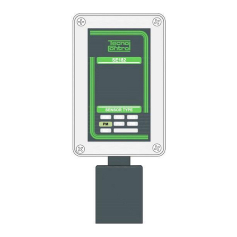
Tecnocontrol SE182PM User manual

Tecnocontrol

Tecnocontrol SE182PM User manual

Tecnocontrol SE136IC2 User manual

Tecnocontrol

Tecnocontrol SE136IC2 User manual

Tecnocontrol TS220E User manual

Tecnocontrol

Tecnocontrol TS220E User manual

Tecnocontrol SE193K Series User manual

Tecnocontrol

Tecnocontrol SE193K Series User manual

Tecnocontrol SE126KM User manual

Tecnocontrol

Tecnocontrol SE126KM User manual

Tecnocontrol SE120KM User manual

Tecnocontrol

Tecnocontrol SE120KM User manual

Tecnocontrol SE138K User manual

Tecnocontrol

Tecnocontrol SE138K User manual

Tecnocontrol SE237P Series User manual

Tecnocontrol

Tecnocontrol SE237P Series User manual

Tecnocontrol TS282K User manual

Tecnocontrol

Tecnocontrol TS282K User manual

Tecnocontrol TS220E Series User manual

Tecnocontrol

Tecnocontrol TS220E Series User manual

Tecnocontrol SE138PX User manual

Tecnocontrol

Tecnocontrol SE138PX User manual

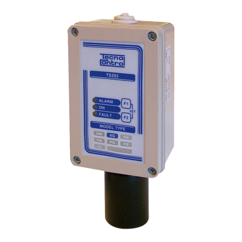
Tecnocontrol TS292KM User manual

Tecnocontrol

Tecnocontrol TS292KM User manual

Tecnocontrol TS293E  Series User manual

Tecnocontrol

Tecnocontrol TS293E Series User manual

Tecnocontrol TS210 IC2 User manual

Tecnocontrol

Tecnocontrol TS210 IC2 User manual

Tecnocontrol Beta SE330K Series User manual

Tecnocontrol

Tecnocontrol Beta SE330K Series User manual

Tecnocontrol SE193K User manual

Tecnocontrol

Tecnocontrol SE193K User manual

Tecnocontrol TS282E Series User manual

Tecnocontrol

Tecnocontrol TS282E Series User manual

Tecnocontrol TS282K User manual

Tecnocontrol

Tecnocontrol TS282K User manual

Tecnocontrol TS210 IC2 User manual

Tecnocontrol

Tecnocontrol TS210 IC2 User manual

Tecnocontrol TS293PM User manual

Tecnocontrol

Tecnocontrol TS293PM User manual

Tecnocontrol TS255CB User manual

Tecnocontrol

Tecnocontrol TS255CB User manual

Tecnocontrol SE138PM User manual

Tecnocontrol

Tecnocontrol SE138PM User manual

Tecnocontrol TS282PM User manual

Tecnocontrol

Tecnocontrol TS282PM User manual

Tecnocontrol TS293IM User manual

Tecnocontrol

Tecnocontrol TS293IM User manual

Popular Gas Detector manuals by other brands

Anton IAQ 8494 quick start guide

Anton

Anton IAQ 8494 quick start guide

SENKO SI-300 operating manual

SENKO

SENKO SI-300 operating manual

EsiWelma Sensigas URS40SI quick start guide

EsiWelma

EsiWelma Sensigas URS40SI quick start guide

Vetus PD1000 Installation and user manual

Vetus

Vetus PD1000 Installation and user manual

Cosmos XP-704 III instruction manual

Cosmos

Cosmos XP-704 III instruction manual

König SAS-GD100 manual

König

König SAS-GD100 manual

STEINEL CO2-AirCheck Signal manual

STEINEL

STEINEL CO2-AirCheck Signal manual

FORENSICS DETECTORS FD-VAPE-WALL user manual

FORENSICS DETECTORS

FORENSICS DETECTORS FD-VAPE-WALL user manual

AGS Mini Merlin CH4CO v2-TX Installation, operation & maintenance manual

AGS

AGS Mini Merlin CH4CO v2-TX Installation, operation & maintenance manual

GEV FMG 1282 user manual

GEV

GEV FMG 1282 user manual

yellow jacket 69373 Series Instruction and operation manual

yellow jacket

yellow jacket 69373 Series Instruction and operation manual

Gas Detection GTD-2000Tx instruction manual

Gas Detection

Gas Detection GTD-2000Tx instruction manual

Riken Keiki SP-220 Series operating manual

Riken Keiki

Riken Keiki SP-220 Series operating manual

Riken Keiki NC-1000 operating manual

Riken Keiki

Riken Keiki NC-1000 operating manual

Macurco ND-2 manual

Macurco

Macurco ND-2 manual

FORENSICS DETECTORS FD-91 quick start guide

FORENSICS DETECTORS

FORENSICS DETECTORS FD-91 quick start guide

Bühler technologies GAS 222.35 AMEX Brief instructions

Bühler technologies

Bühler technologies GAS 222.35 AMEX Brief instructions

STATUS SCIENTIFIC CONTROLS FGD10A-M Installation, Commissioning & Routine Gas Testing Manual

STATUS SCIENTIFIC CONTROLS

STATUS SCIENTIFIC CONTROLS FGD10A-M Installation, Commissioning & Routine Gas Testing Manual

manuals.online logo
manuals.online logoBrands
  • About & Mission
  • Contact us
  • Privacy Policy
  • Terms and Conditions

Copyright 2025 Manuals.Online. All Rights Reserved.