GASER S1500-P User manual

MEATBALL MAKING MACHINE
Mod. S1500-P

-2-
INDEX
1. INDUSTRIAS GASER ............................................................................................................... 3
2. EC DECLARATION OF CONFORMITY ...................................................................................... 4
3. HYGIENE CERTIFICATE........................................................................................................... 5
4. INTRODUCTION....................................................................................................................... 6
4.1 Safety.................................................................................................................................6
4.2 Hygiene ..............................................................................................................................6
5. TECHNICAL SPECIFICATIONS................................................................................................. 7
6. RECEIPT AND START-UP......................................................................................................... 8
6.1 Receipt ...............................................................................................................................8
6.2 Start-up...............................................................................................................................8
7. CLEANING..............................................................................................................................11
8. MAINTENANCE.......................................................................................................................13
9. TROUBLESHOOTING..............................................................................................................14
10. GENERAL DIAGRAM.............................................................................................................15
10.1 Overview.........................................................................................................................15
10.2 Complete meatball former unit..........................................................................................18
10.3 Ram limit switch unit ........................................................................................................19
10.4 Flexible meat entry tube unit.............................................................................................20
10.5 Meatball former unit .........................................................................................................21
10.6. Filter regulator with pressure gauge unit...........................................................................23
11. PNEUMATIC DIAGRAM..........................................................................................................24
12. WIRING DIAGRAM ................................................................................................................25
-3-
1. INDUSTRIAS GASER
Since its foundation in 1969, INDUSTRIAS GASER has specialised in manufacturing a range of
stainless-steel machinery for the meat industry.
Since 1985 we have constantly developed technology for GASER-brand hamburger-forming
machines, developing a distinctive system based on a SIMPLER, MORE EFFECTIVE AND MORE
ECONOMICAL TECHNIQUE.
In the 1990s, INDUSTRIAS GASER expanded into markets in various countries around the world, and
not just in the hamburger sector.
We are aware that our work would be of no value without the trust of our existing clients and partners
or the interest shown by those who wish to join them.
We thank them all.
INDUSTRIAS GASER GASER EUROPA
Salt, Girona, SPAIN L’viv, UKRAINE
INDUSTRIAS GASER Ctra, Bescanó, 15, Pol. Torre Mirona 17190 Salt (Girona) - Spain
Tel. 34 972 23 65 72 | Fax 34 972 23 63 66 | Whatsapp: (34) 679 49 65 06
email: gaser@gaser.com
GASER EUROPA вул.Б.Лепкого,1 81160 смт.Щирець Пустомитівский р-н Львівська область
Украіна - Ukraine
Tel. 38 (03230) 67251/84
Fax 38 (03230) 67191
email: gasereuropa@gaser.com
For more information about the company and its products: www.gaser.com

-4-
2. EC DECLARATION OF CONFORMITY
We declare under our responsibility that the following machine:
Brand: GASER
Model: S1500-P
Serial no.
Year of construction:
is in conformity with the following regulations
UNE-EN ISO 12100:2012
UNE-EN ISO 14120:2016
UNE-EN ISO 14121-1:2008
UNE-EN ISO 13849-1:2008/AC:2009
UNE-EN ISO 4414:2011
and is in conformity with the following directives
Machinery directive: 2006/42/CE
It is forbidden to make any change or modification to the machine without the prior written permission
of our technical department. Use of the machine in these conditions could cause accidents, in which
case INDUSTRIAS GASER S.L. accepts no liability for the improper use of the machine.
Salt,
CARLOS GARGANTA SERRAMITJA
TECHNICAL DIRECTOR INDUSTRIAS GASER S.L.

-5-
3. HYGIENE CERTIFICATE
We declare the machine:
Brand: GASER
Model: S1500-P
Serial no.
Year of construction:
is in conformity with the following regulations
Regulation (EC) 1935/2004, materials and articles in contact with food, repealing Directives
80/590/EEC and 89/109/EEC.
This means that all of the types of steel and plastic from which the machine is constructed and which
are in contact with the meat comply with the hygiene rules and regulations in force.
* Plastic material: polyethylene terephthalate (PETP), white, density 1.37 g/cm3,
Manufactured in accordance with DIN 50014.
* Stainless steel: AISI 304, manufactured in accordance with European regulations EN-10088,
Chemical composition: C≤0.07% Si≤0.75% Mn≤2% Cr=18-19% Ni=8-10%
Salt,
CARLOS GARGANTA SERRAMITJA
TECHNICAL DIRECTOR INDUSTRIAS GASER S.L.

-6-
4. INTRODUCTION
Before using or handling the machine, you must read this manual carefully.
The instructions in this document are, whenever possible, accompanied by illustrations to help with
understanding of how to start, use and clean the machine.
This manual is subject to amendment.
4.1 Safety
It is forbidden to make any change or modification to the machine without the prior written permission
of our technical department. Use of the machine in these conditions could cause accidents, in which
case INDUSTRIAS GASER S.L. accepts no liability for improper use of the machine.
The machine has been designed for use with food products and must be used in the way described in
this manual. Any use other than the specified one will involve risk for the user and for the machine.
INDUSTRIAS GASER S.L. accepts no liability either for damage to the machine or personal injury or
injury to third parties that this use might cause.
4.2 Hygiene
All of the materials used in the manufacture of the machine and which come into contact with food
comply with Regulation 1935/2004. Consequently, the machine has the CE mark.
It is not recommended to use detergents containing chlorine, any of its derivatives or any other product
that could damage the construction materials of the machine.

-7-
5. TECHNICAL SPECIFICATIONS
1. Fits any sausage filler
2. Made from stainless steel
3. Tabletop machine (table optional)
4. Compressed air operation between 4 and 6 bar (kg/cm2)
5. Air consumption: 150 litres/minute
6. Maximum production 15 000 meatballs/hour (depending on type of mixture and the speed of the
sausage filler.
7. Weights of 7, 12, 15, 20, 25, 30 and 35 grams
8. Measurements of the machine 450 × 200 × 600 mm
9. Machine weight 25 kg
-8-
6. RECEIPT AND START-UP
6.1 Receipt
When you receive the machine, you must first check that it is in perfect conditions, without any
damage, dents or knocks.
If there is any problem, we advise you notify the distributor or INDUSTRIAS GASER S.L. directly.
6.2 Start-up
1. It is important that when it starts producing meatballs, the machine is completely clean to ensure it
works properly.
2. It must be connected to a compressed air network. Its normal operating pressure is 4 to 6 kg/cm2,
depending on how quickly you want it to operate.
3. The most appropriate mixtures are those that after being prepared or mixed are kept in the
conservation chamber for several hours at temperatures between 0 and 4 ºC.
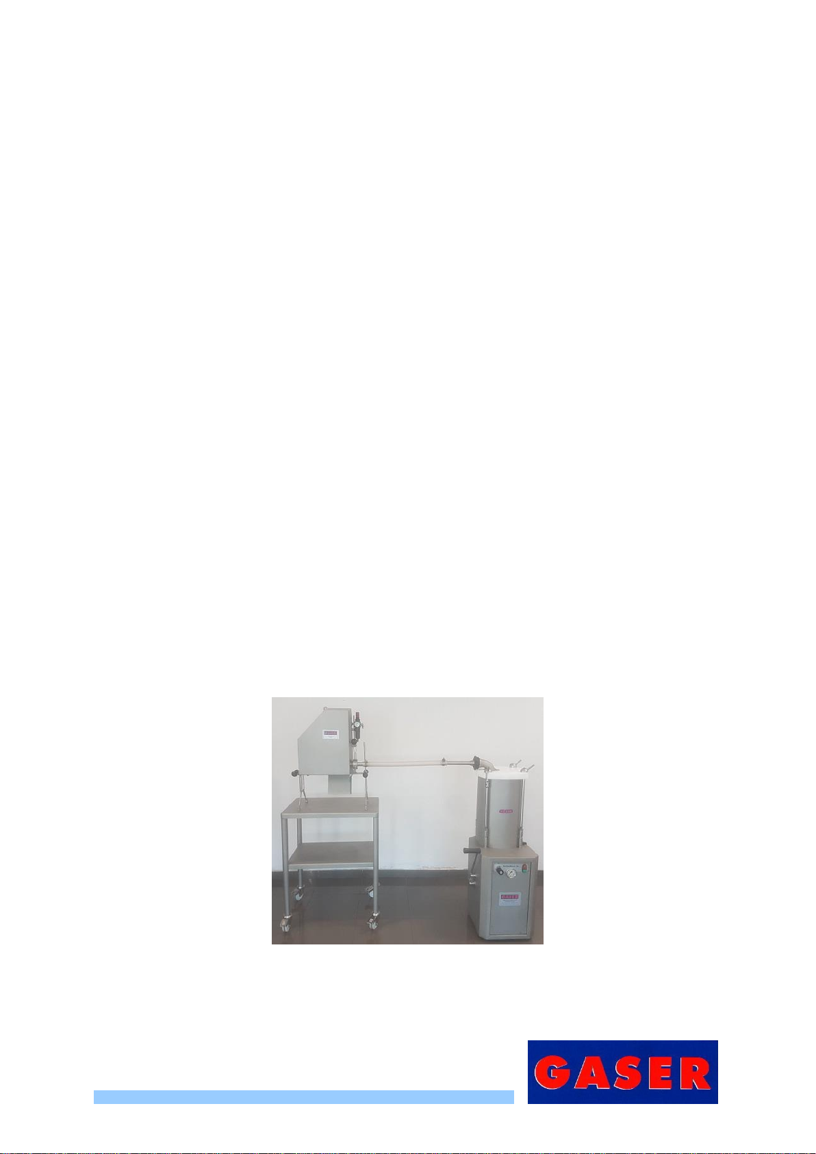
4. These machines can be connected to any hydraulic piston sausage filler or any continuous
sausage filler.
5. The machine is connected to the sausage filler with a 30 mm diameter funnel connected to the
meat entry tube (Pos. 4, Overview)
Image 1, S1500-P with sausage filler

-9-
6. If you want to change the weight of the meatballs, you must change the ball joint (Pos. 3. Meatball
former unit) and the ram (Pos. 2, Meatball former unit).
When making the change, displace the valve (Pos. 3. Overview) so that the protruding pivot and
the fixed part of the valve are in contact when the ram is in its most extended position. Fix the
valve at this point.
Image 2, Changing meatball weight
-10-
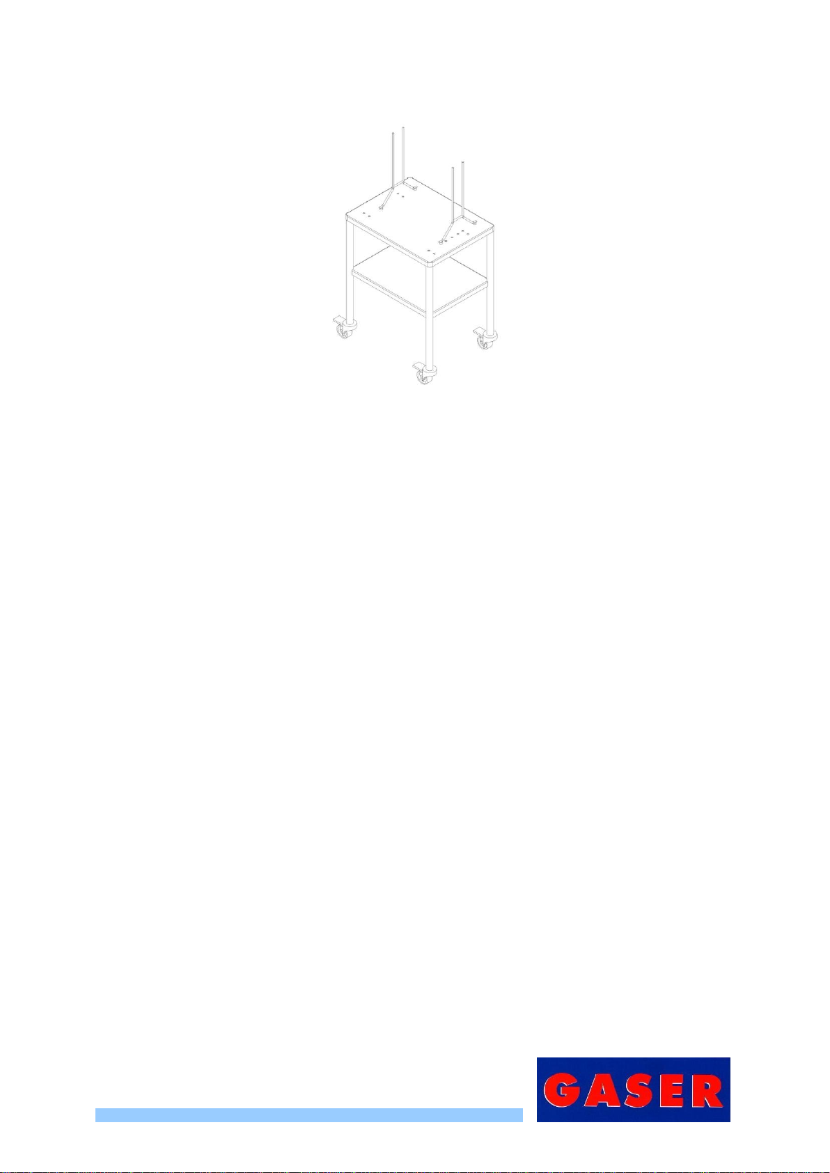
7. The machine can be acquired with a table (RECOMMENDED OPTIONALACCESSORY).
Image 3. S1500-P
8. In case you don’t acquire GASER table, the machine will be sent with two standard feet (Pos. 40,
Overview). In order to work safely you must fix the machine to the table. Working with the machine
when it is not fixed to the table could be a risk for the worker and the machine. The machine could
be suddenly pushed from the filler out of the table and sent down to the floor.
9. Load the filler with the mixture to be used, packing it down slightly, to ensure that there are no
large air pockets in the mixture.
10.The filler lever is fixed; there should never be anyone pulling on this lever. The mixture exit velocity
is controlled using the regulator included on all fillers.
11.When starting the machine up, make sure that the cap nuts that hold the former in place and the
connecting nut (Pos. 13, Overview) are tightened. Also make sure the door is properly closed.
12.The machine is ready to start production.

-11-
7. CLEANING
When you have finished using the machine, it must be cleaned. To do so, follow these steps:
1. Disconnect the meatball former from the sausage filler using the connecting nut (Pos. 13,
Overview) and open the lid using the knob (Pos. 49, Overview).
Image 4. Disconnecting the sausage filler
Image 5. Opening the lid
2. Loosen and remove the two cap nuts and the support guardrail from the former unit (Pos. 7
overview).
Image 6. Loosening cap nuts

-12-
3. Extract the support unit from the former (Pos. 6, Overview) along with the former support (Pos. 2,
overview).
Image 7. Extracting former unit
4. Separate the main components of the former unit and its support.
Image 8. Former unit and support unit components
Image 9. Former unit and support unit assembly
5. Once all the components have been separated they can be cleaned with high pressure water.
Clean the rest of the machine with a damp cloth. Never clean it with pressurised water.
Image 10. Machine ready for cleaning

-13-
8. MAINTENANCE
1. Every 150 hours of work take the lid off the mechanism box (Pos. 46, Overview) and lubricate the
rotating fork pin (Pos. 21, Overview) and the cylinder rods (Pos. 36 and 37, Overview).
2. Regularly check the condition of the moving components: bearings, shafts, cylinders, ball joint,
ram, etc.
3. Periodically check the machine’s seals.
4. Regularly check the condition of the machine’s valves, manifolds and compressed air connections.
5. Periodically check the general condition of the machine.

-14-
9. TROUBLESHOOTING
The table below lists the problems that might occur with the machine, their potential causes and how
to solve them.
Problem
Cause
Solution
The machine does not start
Machine is not connected to
the air network
Connect the machine to the network
Insufficient air pressure
See manual “6.2. Start-up”, point 2
The door is not properly closed
Close the door properly
Ram limit switch poorly
adjusted
See manual “6.2. Start-up”, point 6
There is air pressure but the
machine still will not start or
runs very slowly
Internal air leak
See manual “8. Maintenance”, points 3
and 4
Valve or manifold in poor
condition
See manual “8. Maintenance”, point 4
The machine makes a noise
Internal components not
lubricated
See manual “8. Maintenance”, point 1
The ball joint does not turn
Anti-rotation bearing broken or
in poor condition
See manual “8. Maintenance”, point 2
Mixture too thick
Thin the product
Meat leaking from the former
unit
Cap nuts not tightened
properly
See manual “6.2. Start-up”, point 10
Seals in poor condition
See manual “8. Maintenance”, point 3
Split bearings or ball joint worn
or in poor condition
See manual “8. Maintenance”, point 2

-15-
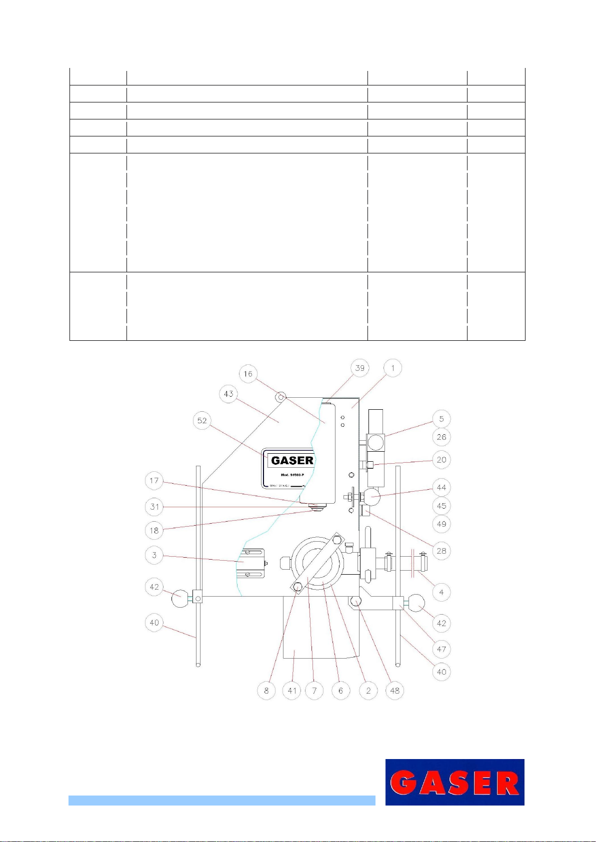
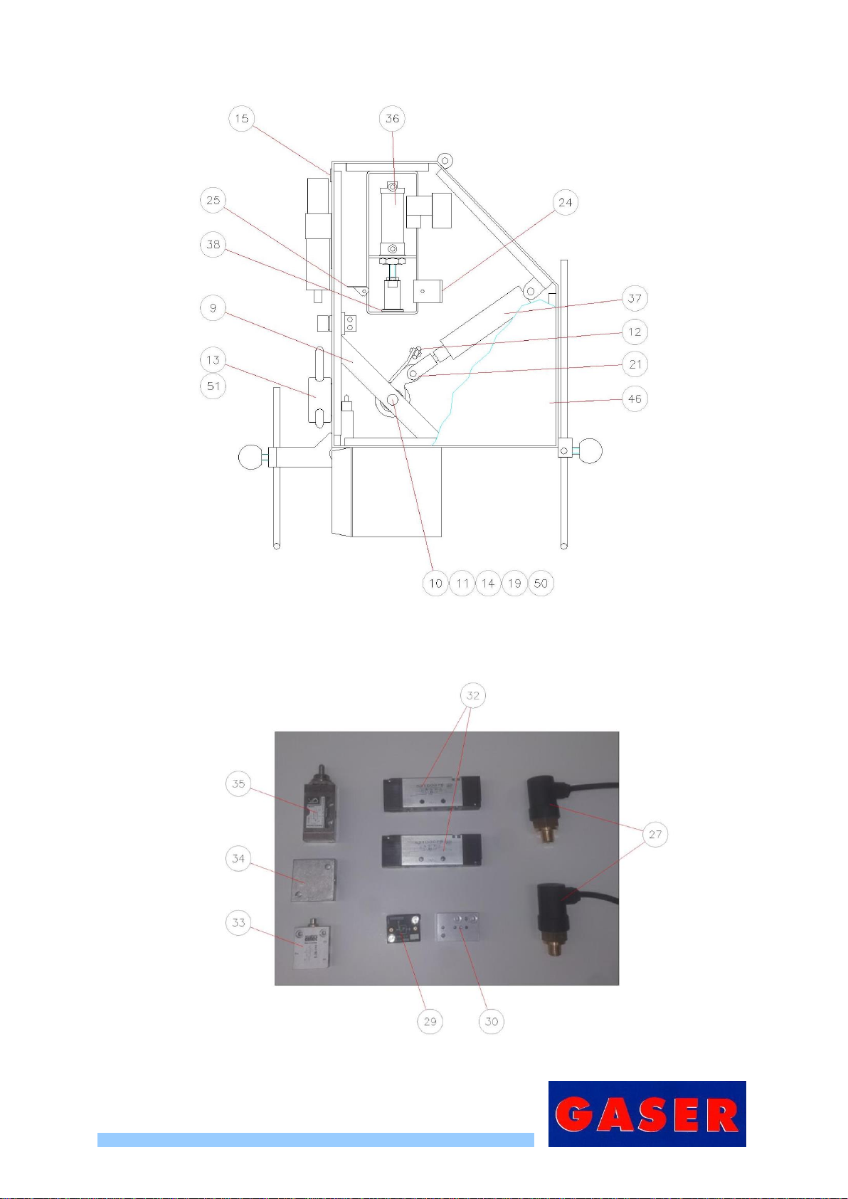
10. GENERAL DIAGRAM
10.1 Overview
Number
Description
Reference
Units
1
MEATBALL MACHINE CHASSIS
15010100
1
2
UNIT MEATBALL FORMER HOLDER
17850000-P
1
3
RAM LIMIT SWITCH UNIT
17870000
1
4
FLEXIBLE MEAT ENTRY TUBE UNIT
17810000
1
5
UNIT FILTER REGULATOR W. PRESSURE GAUGE
17550000
1
6
FORMER UNIT
156X0000
1
7
FORMER SUPPORT HANDRAIL
15020400-P
1
8
FORMER SUPPORT BAR
15071300
2
9
FORMER SHAFT SUPPORT HANDRAIL
15080100
1
10
FORMER SHAFT WITH KEYSEAT
15080200
1
11
FORMER SHAFT SUPPORT
15080700
1
12
INNER MACHINE CRANK
15081400
1
13
STAINLESS SAUSAGE FILLER CONNECTING NUT
15110000
1
14
STAINLESS M16 × 1.5 PNEUMATIC NUT
NE0108M161.5
1
15
REGULATOR HOLE COVER
SI0226GPN300F1
1
16
MEATBALL CYLINDER PROTECTION & SUPPORT
15071000-P
1
17
EJECTOR CYLINDER RETAINER SUPPORT
15071100
1
18
METABALL EJECTOR CYLINDER HEAD
15071200-P
1
19
O-RING EPDM 70 SHAØ14 × 2.5 mm
SI06090142.5
1
20
M8 FIXING KNOB
00040200
1
21
FORK AND PIN UNIT
00670000
1
24
MANIFOLD SUPPORT BRACKET
15081800
1
25
PRESSURE SWITCH SUPPORT
15082000
1
26
AIR FILTER SUPPORT BRACKET
15190100
1
27
VESTA PRESSURE SWITCH UNIT
15720000
2
28
CONTINUOUS SAUSAGE FILLER BASE UNIT
15760000
1
29
NOT VALVE
NE0215NOTC
1
30
NOT VALVE BASE
NE0315709K18
1
31
EJECTOR CYLINDER SCRAPER
NE0215WSW253347
1
32
MANIFOLD
NE0315DJ5214
2
33
E-28310 LIMIT SWITCH
NE0315E28310
1
34
DISTRIBUTOR 40 × 40 × 20 1/4”
NE0315R4040201
1
35
NICKEL VALVE 3/2 1/8”
17740000
1
36
MEATBALL EJECTOR CYLINDER 20 × 25
NE1315020/025
1
-16-
37
VESTA CYLINDER 32 × 75
NE1315032/075
1
38
E-32 DIN471 STAINLESS CIRCLIP
SI0109E320471
1
39
GLAND CAP
SI0226T4838111.5
1
40
DOUBLE FOOT WITHOUT FIXING THREAD
15130100
2
41
OUTLET RAMP
15130200
1
42
FOOT FIXING KNOB
15130300
4
43
FRONT DOOR
15160100
1
44
DOOR LATCH
15160200
1
45
LATCH SLEEVE
15160300
1
46
BACK COVER
15160800
1
47
“T” SUPPORT DOUBLE FRONT FOOT
17591100
1
48
M10 × 100 DIN933 HEX SCREW
FE0108M101000933
1
49
ROUND KNOB M10 Ø40 BLACK
SI0212ESF40M10
1
50
FORMER SHAFT BUSHING
00050400
1
51
INLET NUT INNER CONE
15110300
1
52
MACHINE BRAND STICKER S-1500
PA0230S1500
1
Figure 1. Standard overview 1
-17-
Figure 2. Standard overview 2
Figure 3. Standard overview 3

-18-
10.2 Complete meatball former unit
Ref. 17850000-P
Position
Description
Reference
Units
1
MEATBALL FORMER HOLDER
15020100-P
1
2
KNURLED SCREW VALVE
15020600
1
3
STAINLESS STEEL BALL Ø8mm AISI304
SI0109B08
1
Figure 3. Complete meatball former holder unit

-19-
10.3 Ram limit switch unit
Ref. 17870000
Number
Description
Reference
Units
1
RAM LIMIT SWITCH PROTECTION
15070400
1
2
RAM LIMIT SWITCH BUTTON
15070700
1
3
E25310 BOARD
15081700
1
4
E-25310 LIMIT SWITCH
NE0315E25310
1
5
DIN94 STAINLESS SPLIT PIN Ø2.5 × 20
SI0109PA2502094
1
6
RAM LIMIT SWITCH SPRING
SI0114159.80.75
1
Figure 4. Ram limit switch unit

-20-
10.4 Flexible meat entry tube unit
Ref. 17810000
Number
Description
Reference
Units
1
MEAT ENTRY TUBE
00110300
1
2
BARBED SAUSAGE FILLER CONNECTION TUBE
17810100
1
3
ENTRY TUBE CLAMP
00110200
2
Figure 5. Flexible meat entry tube unit
Table of contents
Other GASER Kitchen Appliance manuals


