GASLAND chef GH12SF User manual

www.gaslandchef.com
8350 Patriot Blvd STE B, N. Charleston, SC 29418
Important! Read these instructions for installation and use carefully. Keep these
instructions for future reference. Any questions regarding the operation, mainte-
nance service or warranty of the appliance should be directed to GASLAND Chef.
Instruction Manual
Built-In Gas Cooktop
Model No. : GH12SF
GH30BF/GH30SF
GH60BF/GH60SF
GH90BF/GH90SF

www.gaslandchef.com
8350 Patriot Blvd STE B, N. Charleston, SC 29418
01
www.gaslandchef.com
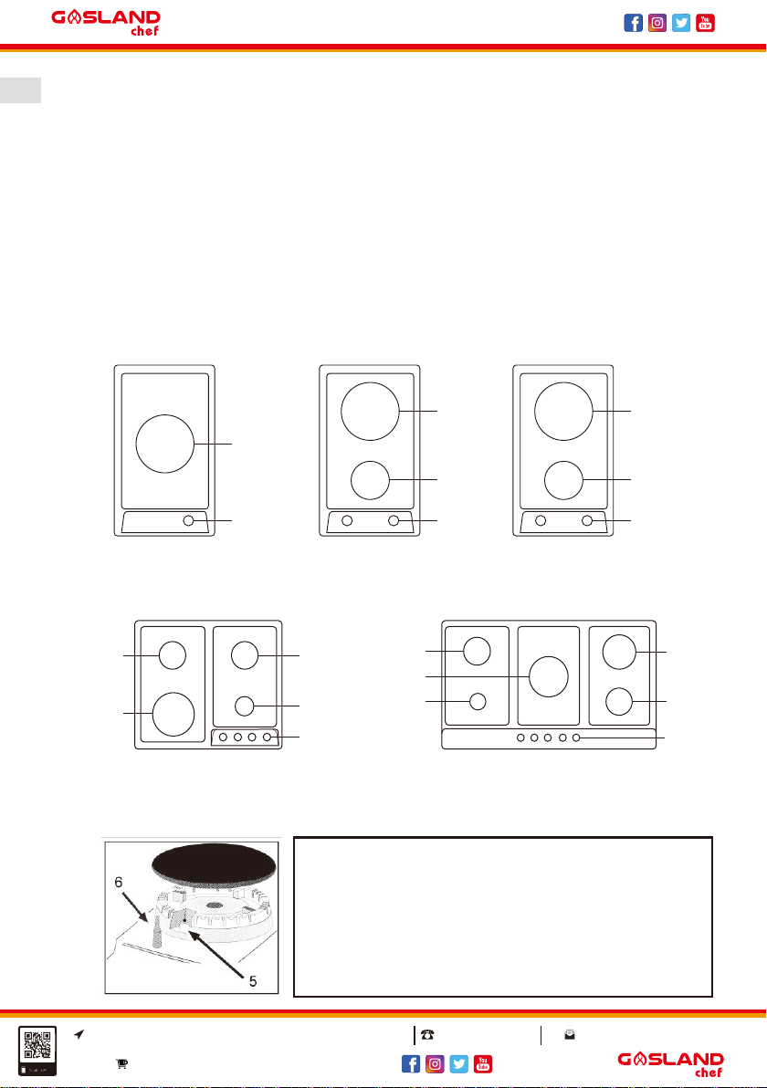
Model No. : GH12SF
Item No.: PG3011S-A2CI
Model No. : GH60BF/GH60SF
Item No.: PG6041G-HCBI1/PG6041S-HCI Model No. : GH90BF/GH90SF
Item No.: PG9051G-HCBI1/PG9051S-HCI
Model No. : GH30SF
Item No.: PG3020BS-CCI
1. Auxiliary burner
2. Semi-rapid burner
3. Rapid burner
4. Triple ring burner
5. Ignitor for gas burners
6. Safety device - activates if the flame accidentally goes out(spills,
drafts, etc.), interrupting the delivery of gas to the burner
7. Control knobs for gas burners
4
7
3
2
7
Model No. : GH30BF
Item No.: PG3021BG-DCB
4
2
7
2
1
7
4
22
43
2
7
1
Congratulations
On the purchase of your new gas cooktop,we recommend that you spend some
time to read this instruction/installation manual in order to fully understand how to
install correctly and operate it. For installation, please read the installation section.
Read all the safety gas carefully before use and keep this instruction/installation
manual for future reference.
Close-up View

www.gaslandchef.com
8350 Patriot Blvd STE B, N. Charleston, SC 29418
02
www.gaslandchef.com
How To Use Your Gas Cooktop
The position of the corresponding gas burner is indicated on each control knob.
Gas burners
The burners are different in size and power. Choose the most appropriate one for
the diameter of the cookware being used.
The burner can be regulated with the corresponding control knob by using one of
the following settings:
OFF
High
Low
On those models fitted with a safety device
The knob must be pressed for about 6 seconds until the flame is lighted and
warmed up.
On those models fitted with an ignitor
The ignition button, identified by the symbol, must be pressed first, then the
corresponding knob is pushed and turned in the counter-clockwise direction to the
"High” setting.
Some models are equipped with an ignition switch incorporated into the control
knob. If this is the case, the ignitor is present, but not the switch(the symbol is
located near each knob).
To light a burner: Simply press the corresponding knob and turn it in the count-
er-clockwise direction to the high setting, keep press until the burner is lighted.
Caution: If the flame goes out accidentally, turn off the gas with the control knob
and try to light it again at least 1 minute later.
To turn off a burner: Turn the knob in the clockwise direction until it is stopped(it
should be on the "." setting).

www.gaslandchef.com
8350 Patriot Blvd STE B, N. Charleston, SC 29418
03
www.gaslandchef.com
How To Keep Your Gas Cooktop In Shape
Before cleaning or performing maintenance on your gas cooktop, disconnect it
from the electrical power supply.
To extend the life of the gas cooktop, it is absolutely indispensable that it is
cleaned carefully, thoroughly and usually, please keep in mind to the following:
● The enameled parts and the glass top must be washed with warm water
without using abrasive powders or corrosive substances which could ruin them;
● The removable parts of the burners should be washed usually with warm water
and soap, make sure to remove caked-on substances;
● Automatic ignitor pin, the end must be cleaned carefully and usually, make
sure ignition keep working normally.
● Stainless steel top plate and other steel parts can be stained if keep touch with
high concentration calcareous water or corrosive detergents(containing phos-
phorus). To extend the life, we advise these parts be rinsed thoroughly with
water and dry them by blowing, It is a good idea to clean up any spills too.
● After glass cooktop working, the surface must be cleaned by a damp cloth to
remove dust or food residues. Glass surface should be cleaned regularly with
warm water and non-corrosive detergent. First, to remove all food residues or
greases with a cleaning scraper, e.g.
Cera (not supplied) (Fig. 1).
While the cooking surface is warm, clean it with a suitable cleaning product and
paper towels, then rub with a damp cloth and dry surface. Such as aluminum foil,
plastic items, objects made of synthetic material, sugar or foods with a high sugar
content that have been melted onto the surface, it must be removed immediately.
While the cooking surface is still hot, clean it with a scraper and a transparent
protective film which prevent to make more dirt. This also protect the surface from
damage caused by food with a high sugar content.
Do not use abrasive sponges or cleaning products, these holds true for chemical-
ly aggressive cleaners, like oven sprays and stain removers(Fig. 2);
Fig. 1 Fig. 2
www.gaslandchef.com
8350 Patriot Blvd STE B, N. Charleston, SC 29418
04
www.gaslandchef.com
● Cleaning the grill/pan support, it is recommended to clean it while it is still hot.
To move grill away from the cooktop and put it in sink, remove the food
residues or grease first, after grill has cooled, rinse it with water.
Greasing the gas valves
Over time, the gas valves may be sticked, and it is difficult to turn on/off. For this
case, should clean the inside of valve and greased it.
Note: This procedure must be performed by a authorized technician.
Practical Advice
Practical advise on using the burners
For best performance, follow these general guidelines:
● Use the appropriate cookware for each burner in order to prevent the flame to
reach the side of the pot or pan see chart.
● Always use cookware with a flat bottom and keep the lid on.
● When the contents come to a boil, turn the knob to "Low".
To identify the type of burner, refer to the designs in the section entitled, "Burner
And Nozzle Specifications".
Practical Advice On Using The Half Fish-kettle
Burner
The two central burners, or half fish-kettle burners, are elliptic in form and can be
turned up to 90°. This makes the cooktop more flexible in terms of how it can be
used.
Burner Ø Cookware diameter(in)
Auxiliary burner 3.9~5.5
Semi-rapid burner 6.3~7.9
Rapid burner 8.7~9.4
Triple ring burner 9.4~10.2

www.gaslandchef.com
8350 Patriot Blvd STE B, N. Charleston, SC 29418
05
www.gaslandchef.com
To turn the two central burners 90°, proceed as follows:
● Make sure that the burners are cool;
● Lift the burner completely out of its housing;
● Replace it in its housing in the position desired;
● Make sure that the burners are positioned correctly before use.
In addition, the two central burners can be used in tandem or separately with
cookware of different.
For best performance, keep in mind the following:
● All types of casseroles can be used on the ceramic glass cooking surface.
However, it is important that the bottom be perfectly flat. Casseroles with
thicker bottom distribute heat more evenly.
The cookware bottom diameter at least as large as the cooking area so that all of
the heat produced by the heating element is used.
● Make sure that the bottom of the pot is always dry and clean to insure good
contact between the cookware and the cooking surface. This also extend the
life of pots and ceramic glass surface as well.
● Do not use the same cookware which for gas burners because the concentrat
ed heat they produce can deform the bottom of the pot. Therefore, you will not
achieve best results when using these pots on the ceramic glass surface.
Installation Instructions For Built-in
The following instructions are directed at the qualified installer, so the installation
and maintenance procedures may be followed in the most professional and
expert manner.
Important: Unplug the electrical connection before performing any maintenance
or regular upkeep work.

www.gaslandchef.com
8350 Patriot Blvd STE B, N. Charleston, SC 29418
06
www.gaslandchef.com
Positioning for gas cooktop
The following requirements must be observed:
a) The room must be fitted with a ventilation system which ventilate smoke and
gases from combustion to the outside of rooms.
This must be done by hood or electric ventilator.
b) The room must be allowed for the influx of the air which for proper combustion.
The air flow for combustion purposes must not less than 70.6 cu ft/h per kW of
installed capacity. The air supply will be effected by influx from the outside
through a duct, its inner cross section is at least 6.1 cu in and must not be
blocked accidentally.
The gas cooktop without safety devices, to prevent flame go out accidentally,
must have a ventilation working on twice volume. For example, a minimum of
12.2 cu in(Fig. 3). Otherwise, the room can be vented indirectly through
adjacent rooms which is fitted with ventilation ducts to the outside. Al though
the adjacent rooms are not shared areas, bedrooms, but fire risk is hidden
(Fig. 4).
c) Intensive and prolonged working of the gas cooktop that need to intensify
ventilation, e.g. opening windows or increasing the power of the air intake
system(if present).
d)Liquefied petroleum gases are heavier than air, so settle it downward. Rooms
in which LPG tanks are installed must be fitted with ventilation to the outside to
avoid of gas leakage.
Therefore, LPG tanks which are empty or partially full, must not be installed or
stored in rooms or spaces below ground level(cellars etc.). It is a good idea to
keep only the tank which is working currently in the room, and make sure that it
is not closed to heating source(ovens, fireplaces, stoves, etc.).
In a chimney stack or branched flue.
(exclusively for cooking appliances)
Adjacent room Room to be vented
Directly to the outside
Examples of ventilation holes
for comburent air.
Fig. 3
Enlarging the ventilation slot
between window and floor.
Fig. 4
www.gaslandchef.com
8350 Patriot Blvd STE B, N. Charleston, SC 29418
07
www.gaslandchef.com
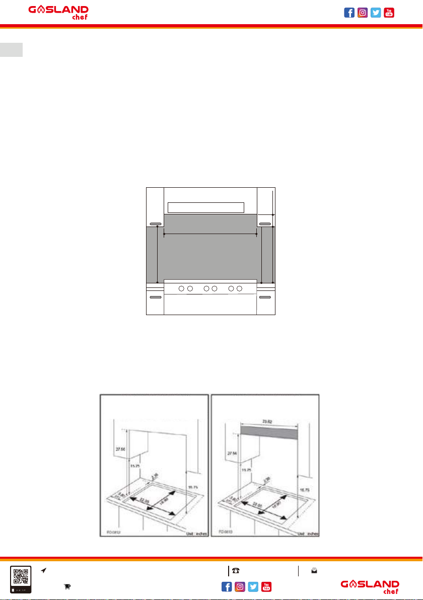
Fig. 5
Installation of built-in gas cooktop(GH60SF for examle)
The gas cooktops are designed with protection degree against excessive heating,
the appliance can be installed next to cabinets, and the height should not exceed
the cooktop.
For a correct installation, the following precautions must be followed:
a) The cooktop may be located in a kitchen, a diner or bed/sitting room, but not in
a bathroom or shower room.
b) The furniture standing near to the unit, it is higher than the working boards,
must be placed at least 4.33 in distance to the edge of the board.
c) The cabinets should be positioned near to the hood at a height of 16.5 in at
least(Fig. 5).
d) Cooktop should be installed directly under a cupboard, the latter should be at
least 27.5 in from the worktop.
e) Fixing fittings(hooks, screws) are provided to place the cooktop on work top,
measure 0.79 to 1.57 in in thickness(see Fig. 6).
HOOD
Min.35.4 in.
Min.16.5 in.
Min.16.5 in.
min.25.5 in. with hood
min.27.5 in. without hood
CLEARANCES REQUIRED
WHEN FITTING THE COOKTOP
WITHOUT A COOKER ABOVE
CLEARANCES REQUIRED
WHEN FITTING THE COOKTOP
WITH A COOKER ABOVE
www.gaslandchef.com
8350 Patriot Blvd STE B, N. Charleston, SC 29418
08
www.gaslandchef.com
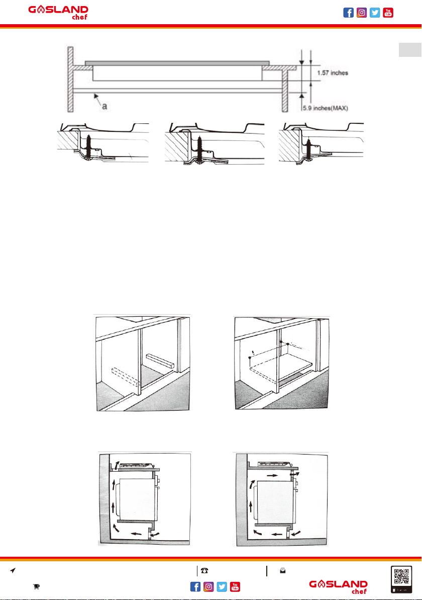
f) In the event the gas cooktop is not installed on a built-in oven, a wooden panel
must be inserted for insulation. This panel must be placed at least 0.787 in
distance from the bottom of cooktop.
lmportant: When installing the cooktop on a built-in oven, the oven should be
placed on two wooden strips, in the case of a joining cabinet surface, remember
to leave a space of 1.77 x 22 in at least from the back side.
When install cooktop on a built-in oven without forced ventilation, ensure that
have air inlets and outlets to ventilate the interior of the cabinet adequately.
Hook position for
H=0.79inches top Hook position for
H=1.91inches top Hook position for
H=1.58inches top
22 in
1.77 in
Fig. 6
Note: Use the hooks contained in the accessories bag.
3.6 cu in
21.96 cu in
7.3 cu in
10.9 cu in
www.gaslandchef.com
8350 Patriot Blvd STE B, N. Charleston, SC 29418
09
www.gaslandchef.com
Gas Connection For Gas Cooktop
The gas cooktop should be connected to the gas-supply by a registered installer.
During installation it is essential to fit an approved gas tap to isolate the supply
from the cooktop for the convenience of any subsequent removal or servicing.
Connect the cooktop to the gas mains or liquid gas, it must be carried out accord-
ing to the prescribed regulation in force, and only after it is ascertained that it is
adaptable to the type of gas to be used. If not, follow the instructions indicated in
the paragraph headed "Adapting To Different Types Of Gas ". In the case of
connection to liquid gas by tank, use pressure regulators that conform to the
regulation in force.
Important: For safety, for the correct regulation of gas use and long life of the
cooktop, ensure that the gas pressure conforms to the indications given in table 1
"Burners And Nozzle Specifications".
Connection to non-flexible tube(copper or steel)
Connection to the gas source must be done in such a way as to not create any
stress points at any part of the gas cooktop.
The cooktop is fitted with an adjustable "L" shape connector and a gasket to the
gas supply.
The connector should be dismounted and the gasket must be replaced.
The feeding connector of the gas to the cooktop is threaded 1/2 in gas tank.
Connection to flexible steel tube
The gas feed connector to the cooktop is threaded, 1/2 in connector for round gas
pipe. Only use pipes and sealing gaskets that conform to the standards currently
in force. The maximum length of the flexible pipes must not exceed 78.7 in. Once
the connection has been made, ensure that the flexible metal tube does not touch
any moving parts and not be crushed.
Check the seal
Once the cooktop was installed, make sure all the connections are properly
sealed, use a soapy soluion to test, never use flame.
www.gaslandchef.com
8350 Patriot Blvd STE B, N. Charleston, SC 29418
10
www.gaslandchef.com
Electrical Connection For Gas Cooktop
The cooktop fitted with a tripolar electrical supply cord which are designed to be
used alternating current .According to the indications on the rating plate located
under the cooktop. The earthing wire can be identified by its yellow-green colour.
In the case of installation over a built-in electric oven, the electrical connections
for the cooktop and oven should be independent, not only for safe purpose, but
also be convenient to remove them in the future.
Fit the supply cord with a standard plug for the demand rate indicated on the
rating plate or connect it directly to the electrical mains. In the latter case, a single
pole switch must be placed between the cooktop and the mains, with a minimum
opening between the contacts of 0.12inch in compliance with current safety
codes(the earthing wire must not be interrupted by the switch). The power supply
cord must be positioned so that it does not reach a temperature in excess of
122°F than room temperature at any point.
Before actual connection make sure that:
● The fuse and electrical system can withstand the load required by the cooktop;
● The electrical supply system is equipped with an efficient earth hook-up
according to the norms and regulations prescribed by law;
● The plug or switch are easily accessible.

www.gaslandchef.com
8350 Patriot Blvd STE B, N. Charleston, SC 29418
11
www.gaslandchef.com
Table 1: Burners And Nozzle Specifications
Adapting the gas cooktop for different types of gas
Auxiliary
Semi rapid
Rapid
Triple Ring
Supply pressures
NG LPG
Normal Burner
Capacities(Btu/kWh)
2800/0.82
5000/1.46
6500/1.90
9500/2.78
Normal Burner
Capacities(Btu/kWh)
2800/0.82
5000/1.46
6500/1.90
9500/2.78
Nozzle 1/100
(in/mm) Nozzle 1/100
(in/mm)
2.9 in/75 mm
3.9 in/100 mm
4.5 in/115 mm
5.1 in/130 mm
2 in/53 mm
2.6 in/68 mm
3.1 in/79 mm
3.6 in/93 mm
12.5mbar 25mbar
Burner
Replacement of burner nozzle: loosen the nozzle with a
dedicated wrench(Fig. 7). Fit the new nozzle according
to the required gas type(see table 1 for reference).
After you have converted the gas cooktop to another gas type, make sure you
have placed a label containing that information on the appliance.
At 15°C and 1013 mbar - dry gas
P.C.I NG 40.1MJ/m³
P.C.I LPG 93.1MJ/m³

www.gaslandchef.com
8350 Patriot Blvd STE B, N. Charleston, SC 29418
12
www.gaslandchef.com
Table 2: How To Convert Gas Source
Adjustment of the reduced valve flow
Valve adjustment
Valve adjustment should be done with the control knob set at burner ON saving
flame position.
Remove the knob and shell, and adjust the flame with a tiny screwdriver(see fig.7
below).
To check the adjusted flame: heat the burner at full open position for 10 minutes.
Then turn the knob into the saving setting. The flame should not extinguish nor
move to the nozzle. If it extinguish or moves to the nozzle, readjust the valves.
Flame selection
As the burners are adjusted correctly, the flame should be light blue, and the
inner flame should be clear. The size of flame depends on the position of the
related control knob.
Fig. 7
Saving flame
Full flame
FlameBurners Converting from LPG
to NG Converting from NG
to LPG
Replace the burner
nozzle according to
the guidelines in table 1
Loosen the adjustment
spindle(see fig.7 below)
and adjust the flame
Replace the burner
nozzle according to
the guidelines in table 1
Loosen the adjustment
spindle(see fig.7 below)
and adjust the flame
Regular
burners

www.gaslandchef.com
8350 Patriot Blvd STE B, N. Charleston, SC 29418
13
www.gaslandchef.com
-Burner ON,
large flame -Burner ON,
small flame(saving mode) -Burner OFF
Fig. 8
Fig. 9 LPG Fig.10 NG
See fig.8 for various operating options(flame size selection). The burner should
be set at a large flame during the initial phase of cooking, it make food boil
quickly. Then should turn knob to the saving flame position to maintain the
cooking. It is possible to adjust the flame size stepless.
It is prohibited to adjust the flame between the burner off and burner
on large flame positions.
High quantity of energy can be conserved if the cooktop is used correctly, param-
eters are designed correctly, and appropriate cookware is used. The energy
conservation be as follows:
● Up to 60% are conserved when proper pots are used,
● Up to 60% are conserved when the unit is operated correctly and the suitable
flame size is chosen.
It is a prerequisite for efficient and energy-saving operation of cooktop that the
burners are kept clean at all times(in particular the flame slots and nozzles).
Pressure regulator adjustment
Please do remember that pressure regulator adjustment should be done by a
qualified technician.
Remove the cap of gas regulator, adjust the spring(see fig.9) to convert the gas to
be LPG; and convert gas type to be NG by inverting the spring and install it(see
fig.10).

www.gaslandchef.com
8350 Patriot Blvd STE B, N. Charleston, SC 29418
14
www.gaslandchef.com
Troubleshooting
If you find gas cooktop cannot work suddenly or cannot work properly.
Before calling customer service for assistance, let us check what we can do.
First of all, check and confirm there have no interruptions to the gas and electrical
supplies.
Particularly if the gas valves keeping turn on.
Notice:
A. Prior to installation, ensure that the local distribution condition(nature of the gas
pressure) and the adjustment of the appliance are compatible.
B. The adjustment conditions for this appliance are stated on the rating label.
C. This gas cooktop is not connected to combustion products evacuation device.
It shall be installed and connected in accordance with current installation
regulations. Particular attention shall be given to the relevant requirement
regarding ventilation.
D. Caution: The use of a gas cooktop lead to the production of heat, moisture
and products of combustion in the room in which it is installed. Ensure that the
kitchen is well ventilated especially when the cooktop is in working: keep
natural ventilation holes open or install a mechanical ventilation device.
Table 3: Adapting To Different Types Of Gas
LPG
NG Pressure
mbar
Nozzle
Diameter
1/100 (in/mm)
Nominal
Charge
g/h l/h btu kcal/h btu kcal/h
3441365702280076
66.5
12.5 2.9 in/75 mm
344136570228002.0 in/53 mm
516204812685000134
516204812685000119
3.9 in/100 mm
744307216946500183
2.6 in/68 mm
744307216946500156
4.5 in/115mm
1290512023749500260
3.1 in/79 mm
1290512023749500224
5.1 in/130 mm
3.6 in/93 mm
25
12.5
25
12.5
25
12.5
25
Reduced
Charge
NG
LPG
NG
LPG
NG
LPG
NG
Burners
Auxiliary
Semi-rapid
Triple-ring
Rapid

www.gaslandchef.com
8350 Patriot Blvd STE B, N. Charleston, SC 29418
15
www.gaslandchef.com
The burner cannot be lighted or the flame is not uniform around the
burner.
Check to make sure that:
● The gas holes on the burner are not clogged.
● All of the movable parts that make up the burner are fixed correctly.
● There are no air flow around the cooking surface.
The flame do not keep lighting to the burner with thermocouple.
Check to make sure that:
● You press the knob all the way.
● You keep pressing the knob for an enough time to activate the thermocouple.
● The gas holes are not clogged in the area corresponding to the thermocouple.
The flame go out while turn knob to "Low" setting.
Check to make sure that:
● The gas holes are not clogged.
● There are no air flow around the cooking surface.
● The minimum has been adjusted correctly.
The cookware is not stable.
Check to make sure that:
● The bottom of the cookware is perfectly flat.
● The cookware is centered correctly on the burner.
● The support grids have not been inverted.
After checked all of these, the gas cooktop still do not work properly, please call
the customer support and inform them of:
--The type of problem.
--The gas cooktop model number(Model....) as indicated on the packing carton.
Never call the technicians who is not authorized, and refuse to use the spare
parts which are not from manufacturer.


www.gaslandchef.com
8350 Patriot Blvd STE B, N. Charleston, SC 29418
Important! Lisez attentivement ces instructions d’installation et utilise ce produit
avec précaution. Conservez ces instructions pour des besoins futurs. Toutes
questions concernant le fonctionnement, le service d’entretien ou la garantie de
l’appareil doit être adressée à GASLAND Chef.
Manuel d’instructions
Plaque de cuisson à gaz intégré
N ° de modèle: GH12SF
GH30BF/GH30SF
GH60BF/GH60SF
GH90BF/GH90SF
01
www.gaslandchef.com
8350 Patriot Blvd STE B, N. Charleston, SC 29418
www.gaslandchef.com
Model No. : GH12SF
Item No.: PG3011S-A2CI Model No. : GH30SF
Item No.: PG3020BS-CCI
4
7
3
2
7
Model No. : GH30BF
Item No.: PG3021BG-DCB
4
2
7
Model No. : GH60BF/GH60SF
Item No.: PG6041G-HCBI1/PG6041S-HCI Model No. : GH90BF/GH90SF
Item No.: PG9051G-HCBI1/PG9051S-HCI
1. Brûleur auxiliaire
2. Brûleur semi-rapide
3. Brûleur rapide
4. Brûleur à triple anneau
5. Allumeur pour brûleurs à gaz
6. L’appareil de sécurité - s'active si la flamme est s'éteint pas accident
(déversements, courants d'air, etc.), interrompant la livraison de gaz
au brûleur
7. Boutons de commande pour les brûleurs à gaz
2
1
7
4
22
43
2
7
1
Félicitations
À l'achat de votre nouvelle table de cuisson à gaz. Nous vous recommandons de
passer du temps à lire ce manuel d’instruction/d’installation afin de bien compren-
dre comment de l’installercorrectement et l’utiliser. Pour l'installation, veuillez s’il
vous plait lire la section d'installation. Li attentivement tout les mesures de
sécurité en ce qui concerne le gaz avant l’utilisation et conservez ce manuel
d’instruction / d’installation des besoins futurs.
Vue rapproché
This manual suits for next models
6
Table of contents
Languages:
Other GASLAND chef Cooktop manuals


