Gasmate GM124-003 Manual

Patio Heater
Model No. GM124-003 and GM124-004
Retain these instructions for future use.
Important: The installer or seller must leave these instructions with the consumer.
3413-04/12
FEATURES:
• Theidealsolutionfor
extendingtheseasonfor
outdoorentertaining
• Maximumoutput39.6MJ/hr
• Directignition
• Adjustableheatoutput
• Safety‘tip-over’switchand
amesafe-guardsystem
• Wheelsforeffortlessmoving
• Operatesforapproximately11
hoursonhighusingaproperly
lled9kgLPGcylinder
• Completewithhoseand
regulator
• Height:2.2m
• TestedtoNZStandards
FOR YOUR SAFETY
Ifyousmellgas:
1. Shutoffthegastothe
appliance.
2. Extinguishanyopename.
3. Ifodourcontinues,
immediatelycallyourgas
supplier.
Donotstoreorusegasolineor
otherammablevapourand
liquidsinthevicinityofthisor
anyotherappliance.
WARNING:
Improperinstallation,adjustment,
alteration,serviceormaintenance
cancauseinjuryorproperty
damage.
Readtheinstructionsthoroughly
beforeinstallingorservicingthis
equipment.
FOR OUTDOOR USE
ONLY
OPERATES ON LPG

23
INSTALLATION
Important Safety Rules:
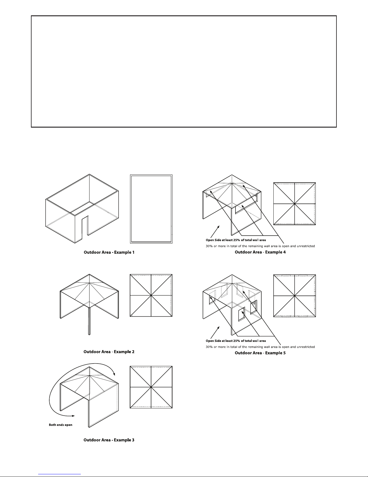
Thisappliancemustonlybeusedinawellventilated
area.
1.Thisapplianceshallnotbeinstalledorusedindoors,
inbuildings,garagesoranyotherenclosedarea.
2. DO NOTplacearticlesonoragainstthisappliance.
3. DO NOTuseorstoreammablematerialsnearthis
appliance.
4.Childrenandadultsshouldbealertedtothehazards
ofhighsurfacetemperatures,burnsandclothing
ignition.
5.Childrenshouldbecarefullysupervisedwhenthey
areintheareaoftheappliance.
6.NEVERhanganythingincludingclothesorother
ammableitemsontheappliance.
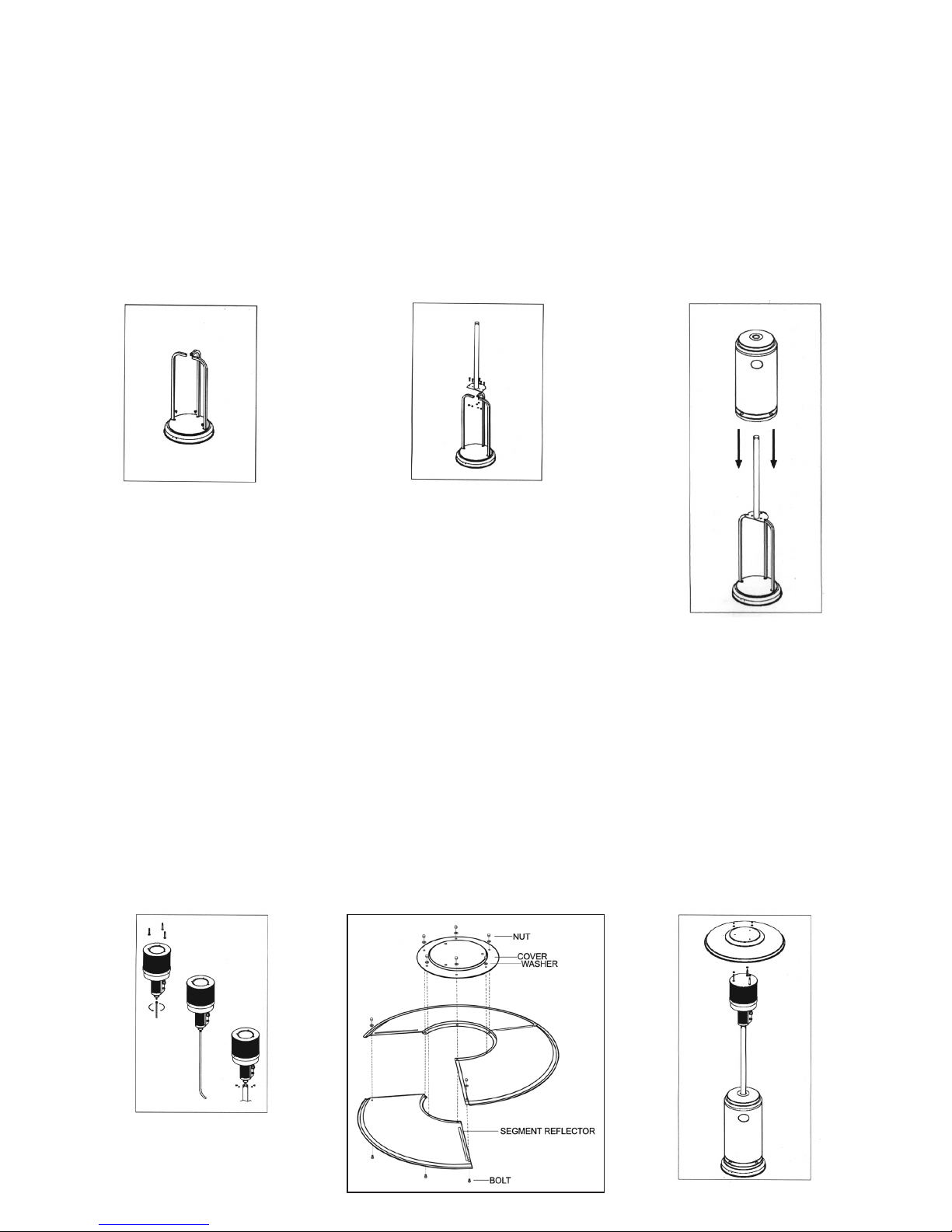
7. DO NOToperatethisapplianceunlessitisfully
assembledwithreectorinplace.
8. DO NOT SPRAY AEROSOLS IN THE VICINITY OF
THIS APPLIANCE WHILE IT IS IN OPERATION.
9.Installationandrepairshouldbedonebyaqualied
serviceperson.Theappliancemustbeinspected
beforeuseandatleastannuallybyaqualied
serviceperson.Morefrequentcleaningmaybe
requiredasnecessary.Itisimperativethatcontrol
compartment,burnersandcirculatingairpassages
oftheapplianceandlightbekeptclean.
Priortoassemblingyourappliance,thefollowingmustbe
reviewed.Compliancewiththefollowingshouldresultin
satisfactoryapplianceoperation.Thisinstructionmanual
shouldberetainedforfuturereference.Theinstallation
mustconformwithlocalcodesorauthorityhaving
jurisdiction.
1. Theapplianceisintendedforresidentialand
nonresidentialoutdoorspaces.Theinstallation
mustconformwithNewZealandStandard5261“Gas
Installations”.
2. Adequateclearancearoundairopeningsintothe
combustionchamber,clearancesfromcombustible
materials,provisionsforaccessibilityandfor
combustionandventilatingairsupplymustbe
maintainedatalltimeswhentheapplianceis
operating.
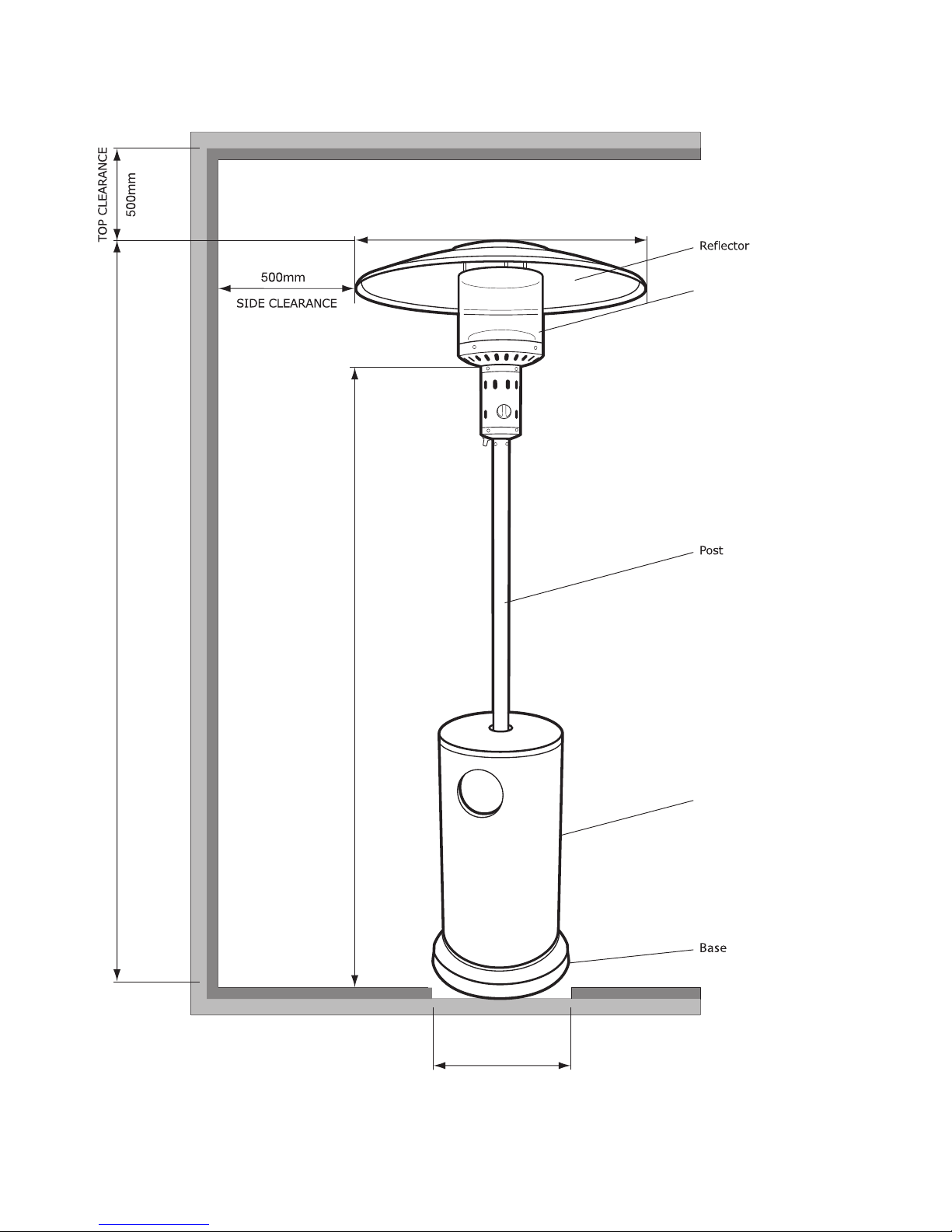
3. Properclearancefromcombustiblematerialsmustbe
maintainedatalltimes.Theminimumclearancesare
asfollows:
Minimum Clearance from Combustibles:
Sides 500 mm Below 1870 mm
Ceiling 500 mm Rear 500 mm
Installation, Operation and Maintenance Instructions
Combustiblematerialsareconsideredtobewood,
compressedpaper,plantbres,plastic,plexiglasor
othermaterialscapableofbeingignitedandburned.
Suchmaterialsshallbeconsideredcombustibleeven
thoughameproofed,re-retardanttreatedorplastered.
Additionalclearancemayberequiredforglass,painted
surfacesandothermaterialswhichmaybedamagedby
radiantorconvectionheat.
4. Theappliancemustbeplacedonalevelandadequate
footingandbereadilyaccessible.
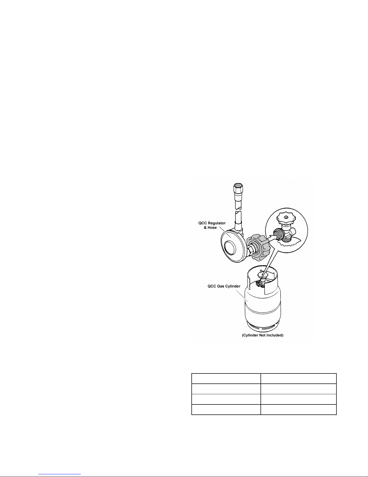
5. Thegasmanifoldsupplypressuremustberegulated
at2.75kPautilisinganapprovedregulator
(suppliedwithappliance).
6. Theappliancemustbeinspectedbeforeeachuse,and
atleastannuallybyaqualiedserviceperson.
a.Theapplianceareamustbekeptclearandfreeof
combustiblematerials,gasolineandother
ammablevapoursandliquids.
b.Gasoricesandburnermustbekeptclearofdirt
andcobwebs.Flowofcombustionandventilation
airthroughtheperforatedportionsoftheappliance
mustnotbeobstructed.Cleaningwithasoft
brushbeforeuseandatleasteverysixmonthsis
recommended.
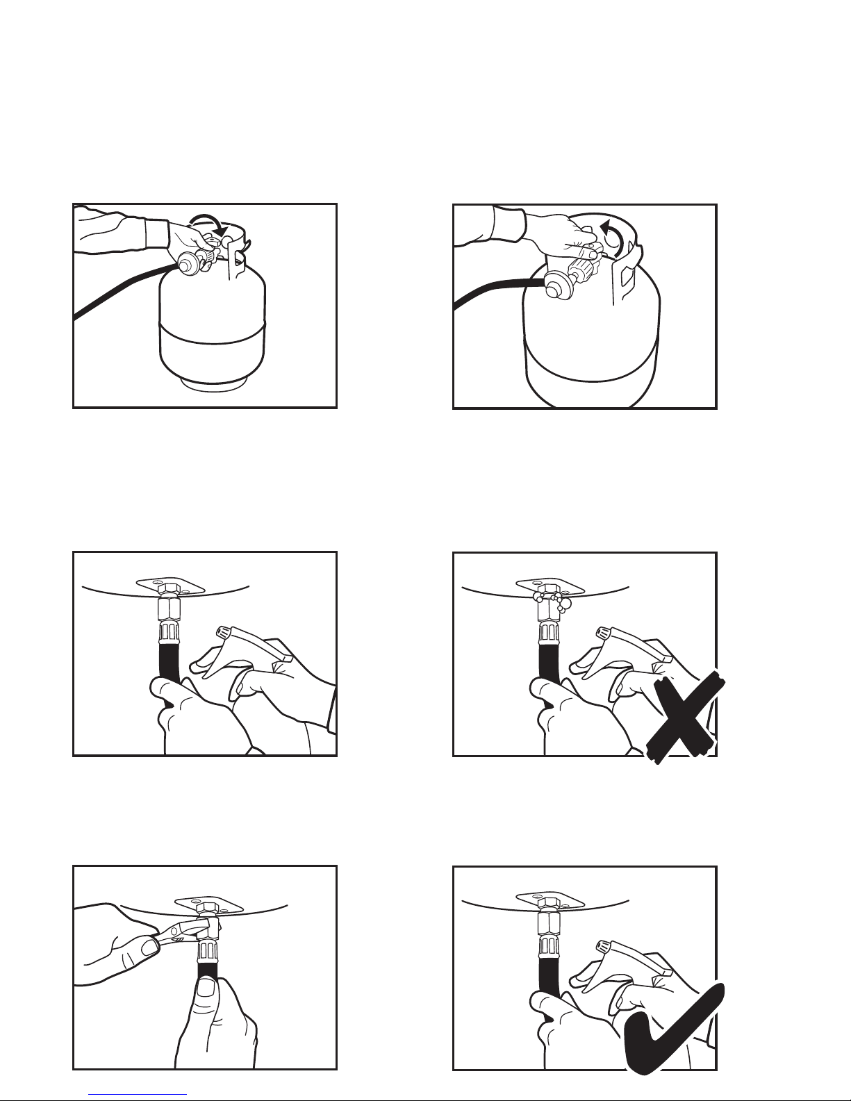
c.Allgasconnectionsshouldbecheckedforleaks
utilisingasoapsolution.Neveruseaameforthis
purpose.
d.Theamepatternattheemittergridshouldbe
visuallycheckedwhenevertheapplianceis
operated.Ifamesextendbeyondsurfaceofthe
emittergridorblacksootisaccumulatingonthe
emittergridorreector,theapplianceshould
beturnedoffimmediately.Theapplianceshouldnot
beoperatedagainuntiltheunitisservicedandor
repaired.
e.Anycleaningagentusedontheapplianceshouldbe
ofanon-combustibleandnon-corrosivenature.
Warmsoapywaterisideal.Whilewashingthe
appliance,besuretokeeptheareaaroundthe
burnerandpilotassemblydryatalltimes.Ifthe
gascontrolisexposedtowaterinanyway,doNOT
trytouseit.Theapplianceshouldberegularly
cleanedandprotectedtoreduceoxidation,ideallya
covershouldbeusedwhennotinuse.
f. Theemittergridnormallydoesnotrequirecleaning
andshouldNEVERbepainted.Thereectormay
becleaned,butneverpainted.

Screw the coupling nut of regulator into the cylinder valve outlet.
Q.C.C. CYLINDER CONNECTION DEVICE
23
7.Thehoseassemblyshouldbeproperlylocatedoutof
pathwayswherepeoplemaytripoverit.Thehose
mustbeprotectedfromcontactwithhotorsharp
surfacesbothduringuseandwhileinstorage.The
hoseassemblyshouldbevisuallyinspectedpriorto
eachuseoftheappliance.Ifexcessiveabrasionor
wearisevident,orthehoseiscut,itmustbe
replacedpriortooperatingtheappliance.The
replacementhoseassemblymaybeobtainedfrom
thedistributor.
8. DO NOTuseanypressureregulatororhose
assemblyotherthanthosesuppliedwiththe
appliance.Replacementpressureregulatorandhose
assemblymustbethosespecied.Replacementparts
maybeobtainedfromthedistributor.
9. Installationanduseofthisappliancemustconform
withNewZealandStandard5261“GasInstallations”.
10.Thisapplianceisdesignedtooperatewithastandard
9KgLPGcylinderwithApprovedCylinderConnection.
11.Thevalveoutletmustbemaintainedingood
condition.Whenthecylinderisnotinuse,besureto
coveritwithadustcap.Aleaktestshouldbe
performedwithsoapywaterwheneverconnecting
anewcylinder.NEVERuseamatchtotestforleaks.
12.TheLPGcylindermustbeturnedoffwheneverthe
applianceisnotinuse.Whentheapplianceistobe
storedindoors,theLPGcylinderandtheappliance
mustbedisconnectedandthecylinderstoredin
accordancewithLPGDangerousGoodsRegulations.
13.Storetheapplianceuprightinanareashelteredaway
fromweatherconditions.Theuseofacoveris
recommended.
14.Theappliancehasbeendesignedwithseveralsafety
featureswhichincludeatipoverswitchandaame
safeguardsystemwhichmeansifthepilotgoesout
theunitwillautomaticallyturnoff.
REGULATOR SAFETY FEATURE
AllQCCregulators(thepartthatattachestothegas
cylindertoregulatetheowofgas)haveasafetyfeature
includedthatrestrictsgasowintheeventofagasleak.
Youcaninadvertentlyactivatethissafetyfeaturewithout
havingagasleak.Thistypicallyoccurswhenyouturn
onthegasusingtheappliancecontrolknobbeforeyou
turnonthegascylindervalve.Ifthegasregulatorsafety
featureactivates,theappliancewilloperatewithreduced
outputasgasowisrestricted.
Thesestepsshouldbetakenrsttoresetthegas
regulatorsafetydevice:
1. Turngascylindervalveoff.
2. Turnapplianceoff.
3. Disconnecttheregulatorfromthegascylinder.
4. Wait30seconds.
5. Reconnecttheregulatortothegascylinder.
6. Leaktesttheconnectionusingasoapywatersolution.
Ensurenobubblesappearbeforeproceeding.
7. Slowlyopenthegascylindervalvealltheway.Donot
putexcessiveforceonthevalveatthefullopen
position,toavoiddamagingthevalve.
8.Lighttheapplianceaspertheinstructionsprovided.
Anymodicationtotheappliancenotdescribedinthe
installationinstructionsmaycompromisethesafetyof
thisappliance.Specialconcernisasfollows:
(1)DO NOTbypassthermocouplesafetyburner;
(2)DO NOToperateappliancewithouttheguards;
Clothingorotherammablematerialsshouldnotbehung
fromtheappliance,orplacedonorneartheappliance.
Theareaabovetheburnermaybeextremelyhot.
Directcontactwiththesemetalsurfacesshouldbe
avoidedinordertopreventburnsorclothingignition.
Q.C.C. CYLINDER CONNECTION DEVICE
Type of Gas General Product LPG
Consumption 39.6 MJ/h
Operating Pressure 2.75 kPa
Injector Size 1.7 mm
Appliancespecicationscanbefoundonthedatalabel.

2200mm
460mm
Cylinder housing
760mm
Burner head
1870mm
45
PATIO HEATER - For Outdoor Use Only
Minimum Clearance from Combustible Surfaces*:
*Combustiblematerialsareconsideredtobewood,compressedpaper,plantbres,plasticorothermaterialsthatare
capableofbeingignitedandburned.

45
GENERAL ASSEMBLY
Connecting & Disconnecting to Gas Source
IMPORTANT:Beforeconnectingand
disconnectingappliancetogassource,make
surecontrolknobisin‘OFF’position.
CAUTION:Whentheapplianceisnotinuse,
thegasmustbeturnedoffatthecylinder.
Familiariseyourselfwiththegeneralinformationand
safetyguidelineslocatedatthefrontofthismanual.
Check:
1. Thecylinderislled.Asloshingsoundwillbeheard
whenshaken.
2. Thecontrolknobisinthe‘OFF’position.
Connecting
1. Ensurecylindervalveisinitsfulloffposition.
2. Checkforanydamagetoeitherthecylinder
connectionorthehose.NEVERattempttouse
damagedequipment.
3. Whenconnectingthehosetothecylindertightenthe
nuttoapositivestopbyhand.
4. Opencylindervalvefully.Ifaleakcanbeheard
ateitherendofthehoseturncylinderoffandtighten
joint.Wait5minutesbeforere-testinganduse
asoapywatersolutiontocheckthejoint.Ifbubbles
appeartheconnectionwillneedtobere-tightened.
Refertopage7formoredetailedinstructionson
connectingtheappliancetothecylinder.
Disconnecting
1. Ensuretheburnercontrolisinthe‘OFF’position.
2. Ensurecylindervalveisinthefulloffposition.
Forstorageandcylinderexchange,disconnecthose
atthecylinderonly,DONOTdisconnecthosefrom
appliance.

ASSEMBLY INSTRUCTIONS
Step 1
1-1.Putthe3postbracketsoneach
positiononthebaseasshownin
thepicure.
1-2.Use3M8x16mmboltstojoin
thepostbracketsandbase.
Step 2
2-1.Putthepostonthetopof3post
brackets.
2-2.Use6M6x35mmboltsand
nutstoconnecttheposttothe
postbrackets.Tightenthebolts
andnuts.
2-3.Filltheplasticcontainerinthe
basewithsand.
Step 3
Placethecylinderhousingonthe
stand.
Step 4
4-1.Securethe390mmpins
(reectorsupportbolts)onthe
capofamescreen.
4-2.Routethegashoseupthrough
thepostandoutofthetop.
4-3.Connectthegashosetothegas
burnerinletconnector.
4-4.Connecttheregulatortothe
hoseandagascylinderandleak
testbothoftheconnections
usingasoapywatersolution.
4-5.Attachthecompletedburnerto
thepostwith4M6x10mm
bolts.
Step 5
5-1.Overlapthe3partsofreector
segmentsandattachwith3
screws,washersandnuts.
5-2.Placeroundpartofreectorover
the3segmentsandattachwith
6screws,washersandnuts.
Step 6
6-1.Placeawasheroneachreector
supportbolt.
6-2.Fastenthereectorwith3
washersand3M8castlenuts.
Tools Required-Adjustablespanner
Note:Removeanytransitprotectionmaterial
67

STEP 7
Ensure cylinder valve is in its full off position. Check
for any damage to either the cylinder connection or
the hose. NEVER attempt to use damaged equipment.
Attach the regulator and hose to your gas cylinder.
Tighten the nut to a positive stop by hand.
STEP 8
Turn on the gas cylinder ensuring that the control knob
on the outdoor heater is turned OFF at this point.
DO NOT ATTEMPT TO LIGHT THE HEATER!!.
STEP 9
Use a solution of soapy water (dishwashing liquid and
water is fine). Brush it on or use a spray bottle as
shown in the drawing. Ensure the connections have a
good coating.
STEP 10a
If the connection is leaking, bubbles will start to grow
in the soapy solution. If this happens shut off the gas
supply at the cylinder.
STEP 10b
Tighten the connections using a crescent then repeat
steps 8-9.
STEP 10c
The connection is gas tight when no bubbles grow
around the gas connection.
ASSEMBLY INSTRUCTIONS
67

87
TEST FIRING APPLIANCE
Testreheater,followingthelightinginstructionsonheaterpost.Leaktestallgasconnectionswithsoapywater.Soap
bubblesindicategasleakage.DO NOTuseamatchtotestforgasleaks.
WARNING:Whitesmokemayappeararoundtheradiantheadduringtherstminuteoftheinitialring.
TROUBLE SHOOTING
LIGHTING INSTRUCTIONS
Step 1.
Ensurethatthecontrolknobisoff.Slowlyopenthegas
cylindervalve.
Step 2.
Pushincontrolknobandturnanti-clockwiseto‘HIGH’
whilstsimultaneouslypushingtheignitorbuttonseveral
times.
Step 3.
Checkforameattheburner.Ifburnerdoesnotlight
immediatelyturncontrolknobto‘OFF’positionandtry
againfromthestart.Allow30secondsbetweenignition
attemptsforgastodissipate.Severalattemptsmay
benecessary.
Failure to follow this lighting procedure may result
in ame roll out beyond the emitter grid.
Step 4.
Withtheburneralightkeepcontrolknobdepressedfor
15seconds.
Step 5.
Forminimumheatpushinandturnthecontrolknobto
‘LOW’.
Step 6.
Toturnheateroff,turnthecontrolknobto‘OFF’.
P
u
s
h
t
o
t
u
r
n
O
F
F
P
u
s
h
t
o
t
u
r
n
O
F
F
LOW
H
I
G
H
LOW
H
I
G
H
Problem Possible Causes
Mainburnerwon’tlight •Nogas
•Lowgaspressure
•Blockageinorice
•Manualvalvenotin‘LOW’or‘HIGH’position
Note:Iftheappliancecannotbeadjustedtoperformcorrectlyitshouldnotbeuseduntilservicedorrepaired.
Warning:Improperinstallation,adjustment,alteration,serviceormaintenancecancauseinjuryorproperty
damage.Anymodicationsoradjustmentsmadetoproductwithoutpriorauthorityfromthemanufacturer
willvoidanywarrantyclaims.Readtheinstallation,operatingandmaintenanceinstructionsthoroughlybefore
installingorservicingthisequipment.

DIAGRAMMATIC REPRESENTATIONS OF OUTDOOR AREAS
Thefollowingfiguresarediagrammaticrepresentationsofoutdoorareas.Rectangularareashavebeenusedinthese
figures–thesameprinciplesapplytoanyothershapedarea.
SAFE APPLIANCE LOCATIONS
Thisapplianceshallonlybeusedinanabovegroundopen-airsituationwithnaturalventilation,withoutstagnantareas,
wheregasleakageandproductsofcombustionarerapidlydispersedbywindandnaturalconvection.
Any enclosure in which the appliance is used shall comply with the following:
Anenclosurewithwallsonallsides,butatleastonepermanentopeningatgroundlevelandnooverhead
cover(seeExample1).
Withinapartialenclosurethatincludesanoverheadcoverandnomorethantwowalls(seeExample2&3).
Within a partial enclosure that includes an overhead cover and more than two walls, the following
will apply:
atleast25%ofthetotalwallareaiscompletelyopen,and
atleast30%oftheremainingwallareaisopenandunrestricted(seeExample4&5).
In the case of balconies, at least 20% of the total wall area shall be and remain open and unrestricted.
Gasmate®is a registered trademark of: Sitro Group Australia Pty Ltd www.gasmate.com.au
Aber, Hamilton, N.Z. www.gasmate.co.nz
Gasmate®is a registered trademark of: Sitro Group Australia Pty Ltd www.sitro.com.au
Aber, Hamilton, N.Z. www.gasmate.co.nz
SAFE APPLIANCE LOCATIONS
This appliance shall only be used in an above ground open-air situation with natural ventilation, without
stagnant areas, where gas leakage and products of combustion are rapidly dispersed by wind and natural
convection.
Any enclosure in which the appliance is used shall comply with one of the following:
An enclosure with walls on all sides, but at least one permanent opening at ground level and
no overhead cover (see Example 1).
Within a partial enclosure that includes an overhead cover and no more than two
walls (see Example 2 & 3).
Within a partial enclosure that includes an overhead cover and more than two walls,
the following will apply:
at least 25% of the total wall area is completely open, and
at least 30% of the remaining wall area is open and unrestricted (see Example 4 & 5).
In the case of balconies, at least 20% of the total wall area shall be and remain open and unrestricted.
The following figures are diagrammatic representations of outdoor areas. Rectangular areas have been used in these
figures - the same principles apply to any other shaped area.
87


This manual suits for next models
1
Table of contents
Other Gasmate Patio Heater manuals

Gasmate
Gasmate PH600 Series User manual

Gasmate
Gasmate PH2160 User manual

Gasmate
Gasmate PH2063 Manual

Gasmate
Gasmate PH2260 User manual

Gasmate
Gasmate STELLAR BLACK PH7056 User manual

Gasmate
Gasmate NG1P45 Manual

Gasmate
Gasmate Blaze Manual

Gasmate
Gasmate EH305 User manual

Gasmate
Gasmate GM135-009 Manual

Gasmate
Gasmate GM120-001 User manual