GasTech GTD2000-Tx User manual

t +61 8 6108 0000 e info@gastech.com w gastech.com
GTD2000-Tx
OPERATOR’S MANUAL
Note
• Inspection and calibration are recommended at least once every 3
months to ensure accurate operation of the Gas detector using
calibration gas depending on the type of gas.
• Negligence of periodic inspection and calibration may cause
malfunction of the device due to the aging of the Sensor.
• Only qualified personnel with professional s ills on Gas detector may
disassemble the unit if necessary.
• For further information on Gas detector inspection and correction,
please contact us at our technical department, e-mail or web site.
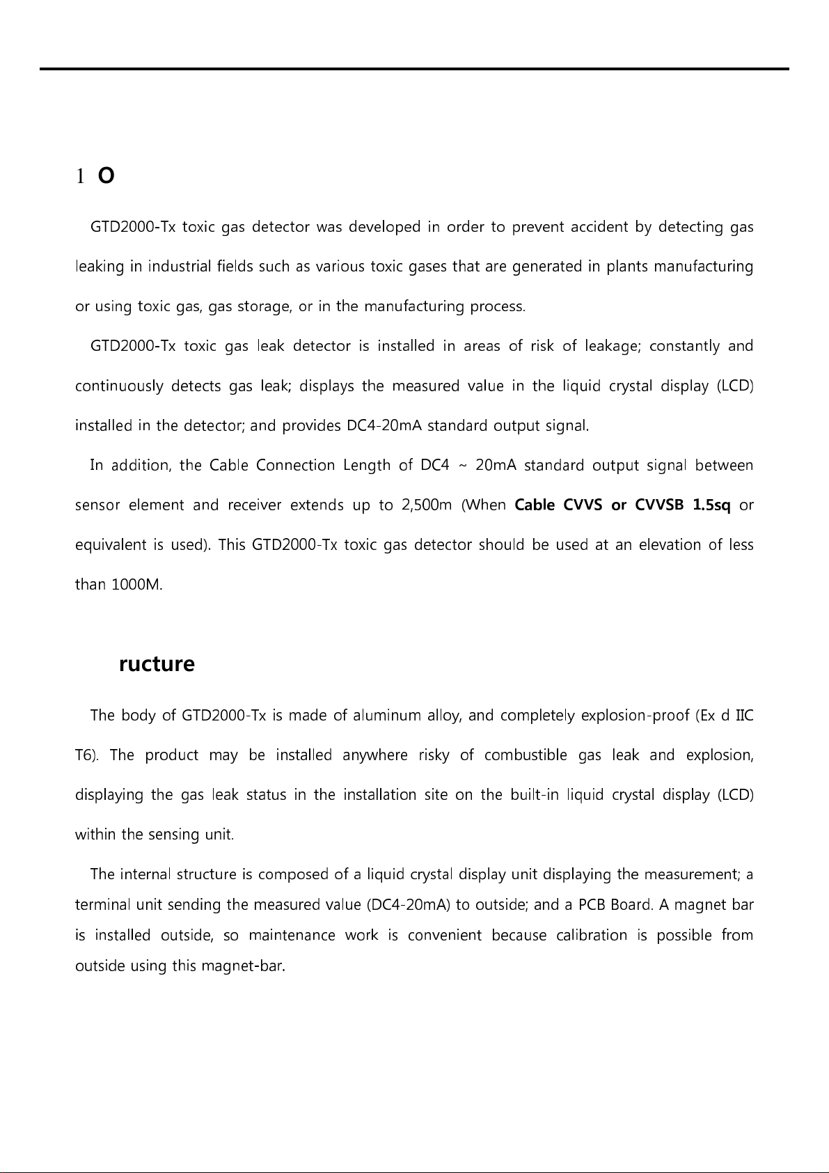
1. Overview
GTD2000-Tx toxic gas detector was developed in order to prevent accident by detecting gas
leaking in industrial fields such as various toxic gases that are generated in plants manufacturing
or using toxic gas, gas storage, or in the manufacturing process
GTD2000-Tx toxic gas leak detector is installed in areas of risk of leakage; constantly and
continuously detects gas leak; displays the measured value in the liquid crystal display (LCD)
installed in the detector; and provides DC4-20mA standard output signal
In addition, the Cable Connection Length of DC4 ~ 20mA standard output signal between
sensor element and receiver extends up to 2,500m (When
Cable CVVS or CVVSB 1.5sq
or
equivalent is used) This GTD2000-Tx toxic gas detector should be used at an elevation of less
than 1000M
2. Structure
The body of GTD2000-Tx is made of aluminum alloy, and completely explosion-proof (Ex d IIC
T6) The product may be installed anywhere risky of combustible gas leak and explosion,
displaying the gas leak status in the installation site on the built-in liquid crystal display (LCD)
within the sensing unit
The internal structure is composed of a liquid crystal display unit displaying the measurement; a
terminal unit sending the measured value (DC4-20mA) to outside; and a PCB Board A magnet bar
is installed outside, so maintenance work is convenient because calibration is possible from
outside using this magnet-bar
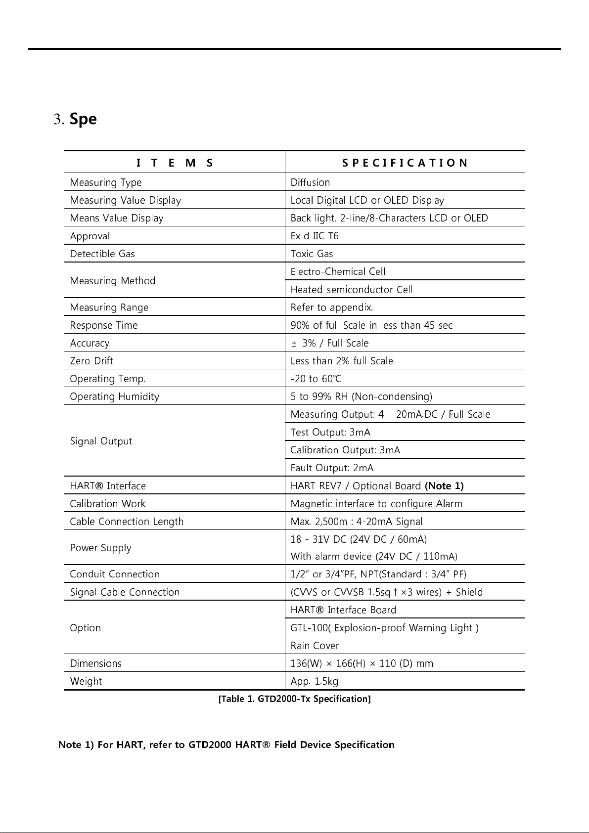
3. Specification
I T E M S S P E C I F I C A T I O N
Measuring Type Diffusion
Measuring Value Display Local Digital LCD or OLED Display
Means Value Display Back light, 2-line/ -Characters LCD or OLED
Approval Ex d IIC T6
Detectible Gas Toxic Gas
Measuring Method Electro-Chemical Cell
Heated-semiconductor Cell
Measuring Range Refer to appendix.
Response Time 90% of full Scale in less than 45 sec
Accuracy ± 3% / Full Scale
Zero Drift Less than 2% full Scale
Operating Temp. -20 to 60℃
Operating Humidity 5 to 99% RH (Non-condensing)
Signal Output
Measuring Output: 4 – 20mA.DC / Full Scale
Test Output: 3mA
Calibration Output: 3mA
Fault Output: 2mA
HART
®
Interface HART REV7 / Optional Board
(Note 1)
Calibration Work Magnetic interface to configure Alarm
Cable Connection Length Max. 2,500m : 4-20mA Signal
Power Supply 1 - 31V DC (24V DC / 60mA)
With alarm device (24V DC / 110mA)
Conduit Connection 1/2” or 3/4”PF, NPT(Standard : 3/4” PF)
Signal Cable Connection (CVVS or CVVSB 1.5sq↑×3 wires) + Shield
Option
HART
®
Interface Board
GTL-100( Explosion-proof Warning Light )
Rain Cover
Dimensions 136(W) × 166(H) × 110 (D) mm
Weight App. 1.5kg
[Table 1. GTD2000-Tx Specification]
Note 1) For HART, refer to GTD2000 HART® Field Device Specification
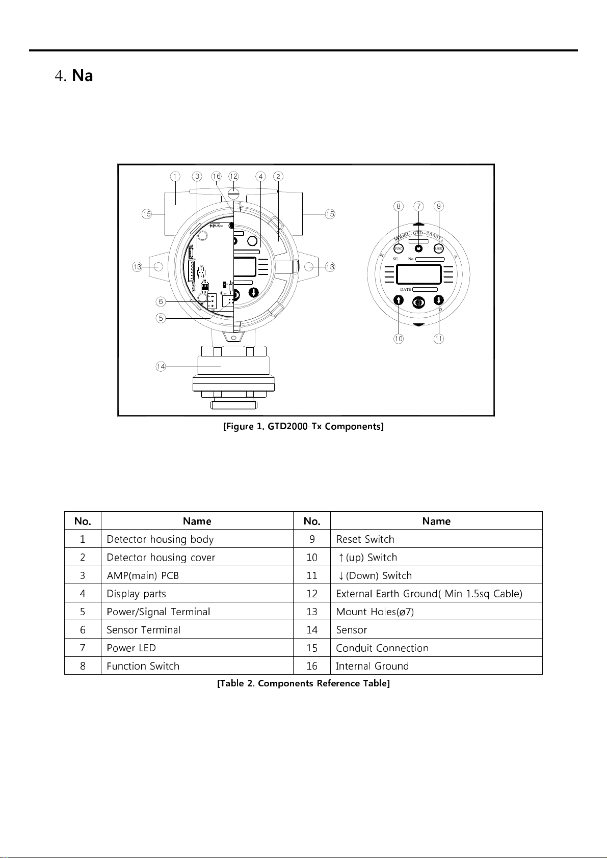
4. Name of Components and Main features
4.1. Components
RESET
12
34
6
7
8 9
10 11
14
13
15
1216
SERIAL No.
DATE
G
:
L
E
D
O
M
x
T
0
0
0
2
-
D
T
R
O
T
C
E
T
E
D
S
R
O
K
N
I
E
D
A
A
E
M
A
G
C
O
.
,
L
T
D
.
G
A
S
T
R
O
N
U
P
T
F
I
L
P
R
E
S
S
L
U
P
T
F
I
P
R
E
S
S
5
15
13
[Figure 1. GTD2000-Tx Components]
No. Name No. Name
1 Detector housing body 9 Reset Switch
2 Detector housing cover 10 ↑(up) Switch
3 AM (main) CB 11 ↓(Down) Switch
4 Display parts 12 External Earth Ground( Min 1.5sq Cable)
5 ower/Signal Terminal 13 Mount Holes(ø7)
6 Sensor Terminal 14 Sensor
7 ower LED 15 Conduit Connection
8 Function Switch 16 Internal Ground
[Table 2. Components Reference Table]
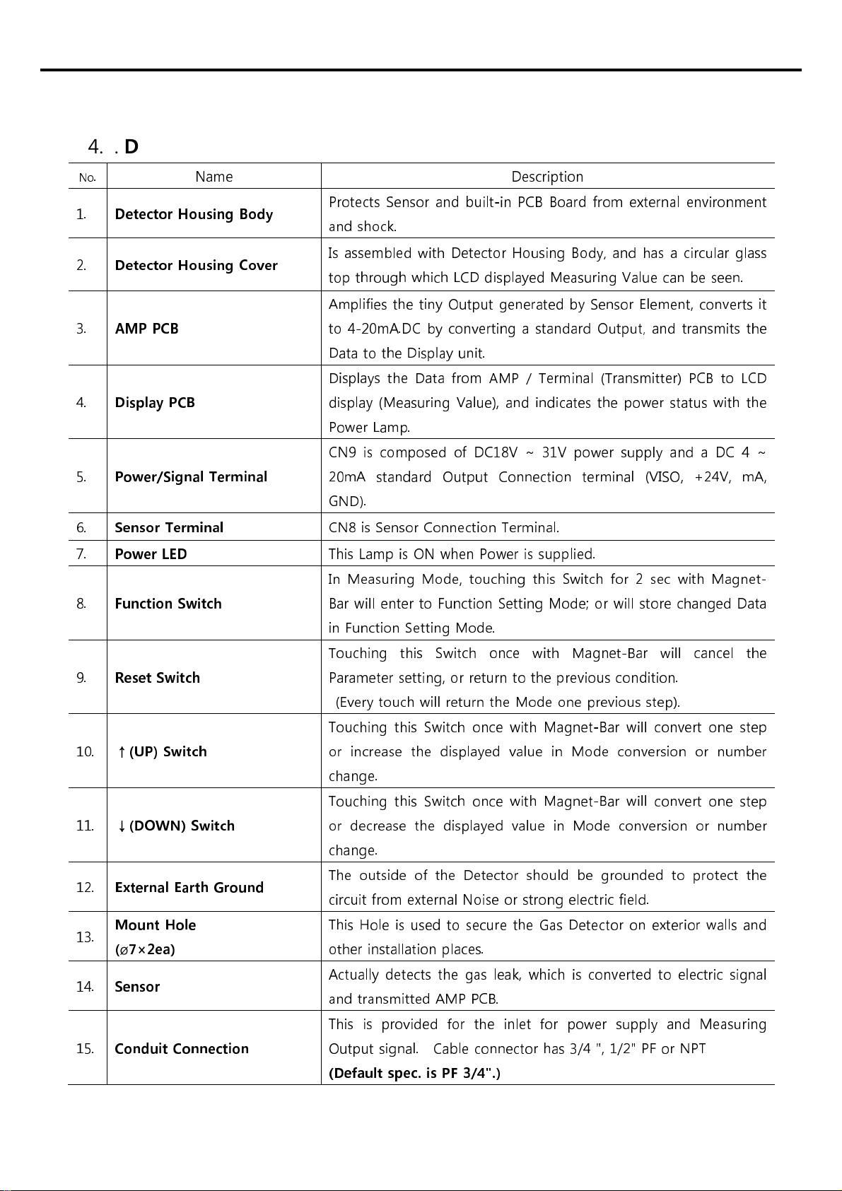
4.2. Description of components
No
. Name Description
1.
Detector Housing Body
rotects Sensor and built-in CB Board from external environment
and shock.
2.
Detector Housing Cover
Is assembled with Detector Housing Body, and has a circular glass
top through which LCD displayed Measuring Value can be seen.
3.
AMP PCB
Amplifies the tiny Output generated by Sensor Element, converts it
to 4-20mA.DC by converting a standard Output, and transmits the
Data to the Display unit.
4.
Display PCB
Displays the Data from AM / Terminal (Transmitter) CB to LCD
display (Measuring Value), and indicates the power status with the
ower Lamp.
5.
Power/Signal Terminal
CN9 is composed of DC18V ~ 31V power supply and a DC 4 ~
20mA standard Output Connection terminal (VISO, +24V, mA,
GND).
6.
Sensor Terminal
CN8 is Sensor Connection Terminal.
7.
Power ED
This Lamp is ON when ower is supplied.
8.
Function Switch
In Measuring Mode, touching this Switch for 2 sec with Magnet-
Bar will enter to Function Setting Mode; or will store changed Data
in Function Setting Mode.
9.
Reset Switch
Touching this Switch once with Magnet-Bar will cancel the
arameter setting, or return to the previous condition.
(Every touch will return the Mode one previous step).
10.
↑(UP) Switch
Touching this Switch once with Magnet-Bar will convert one step
or increase the displayed value in Mode conversion or number
change.
11.
↓(DOWN) Switch
Touching this Switch once with Magnet-Bar will convert one step
or decrease the displayed value in Mode conversion or number
change.
12.
External Earth Ground
The outside of the Detector should be grounded to protect the
circuit from external Noise or strong electric field.
13.
Mount Hole
(
ø
7×2ea)
This Hole is used to secure the Gas Detector on exterior walls and
other installation places.
14.
Sensor
Actually detects the gas leak, which is converted to electric signal
and transmitted AM CB.
15.
Conduit Connection
This is provided for the inlet for power supply and Measuring
Output signal. Cable connector has 3/4 ", 1/2" F or N T
(Default spec. is PF 3/4".)
16.
Internal Ground
The inside of the Detector should be grounded to protect the
circuit from external Noise or strong electric field.
[Table . Components details table]
5. Terminal wiring diagram
Warning
Never install, uncover, or manipulate the Detector other than authorized
personnel or installation/repair service person from Gastron, or serious loss of life and property
damage such as fire or explosion may occur. In addition, check around for explosive Gas or
flammable substances, followed by turning OFF before any work.
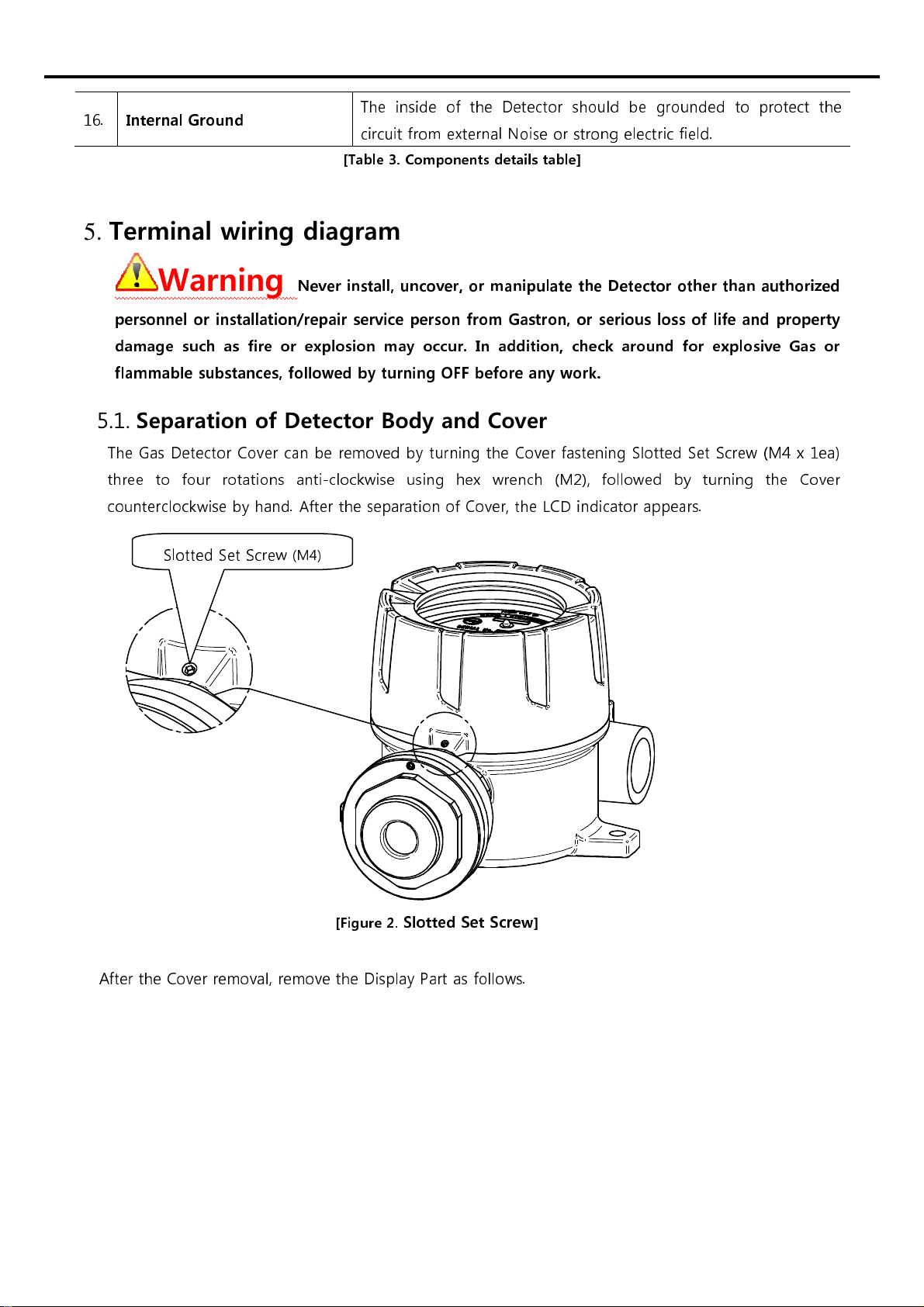
5.1. Separation of Detector Body and Cover
The Gas Detector Cover can be removed by turning the Cover fastening Slotted Set Screw (M4 x 1ea)
three to four rotations anti-clockwise using hex wrench (M2), followed by turning the Cover
counterclockwise by hand. After the separation of Cover, the LCD indicator appears.
[Figure 2.
Slotted Set Screw
]
After the Cover removal, remove the Display art as follows.
Slotted Set Screw
(M4)
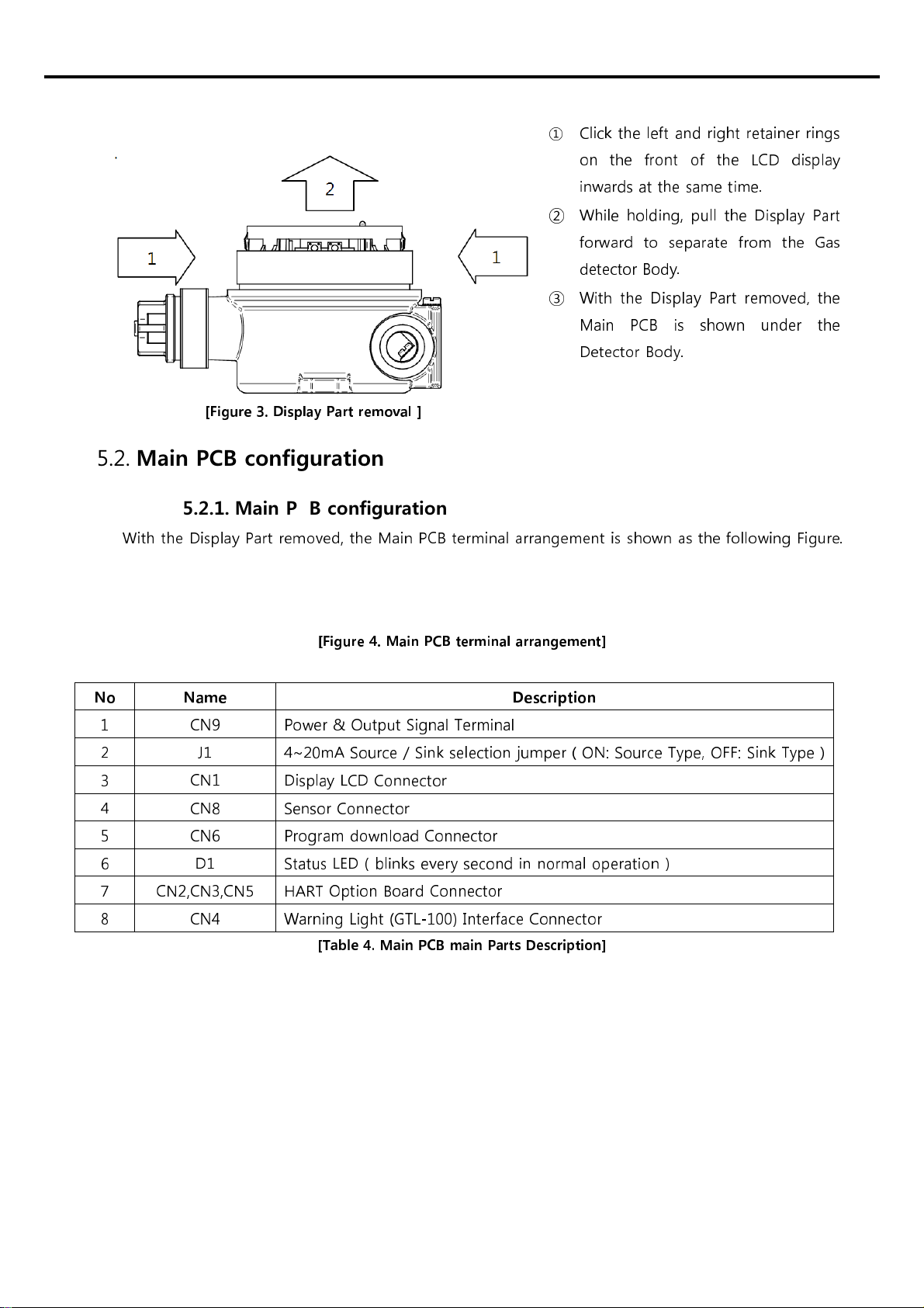
[Figure . Display Part removal ]
①
Click the left and right retainer rings
on the front of the LCD display
inwards at the same time.
②
While holding, pull the Display art
forward to separate from the Gas
detector Body.
③
With the Display art removed, the
Main CB is shown under the
Detector Body.
5.2. Main PCB configuration
5.2.1. Main PCB configuration
With the Display art removed, the Main CB terminal arrangement is shown as the following Figure.
[Figure 4. Main PCB terminal arrangement]
No Name Description
1 CN9 ower & Output Signal Terminal
2 J1 4~20mA Source / Sink selection jumper ( ON: Source Type, OFF: Sink Type )
3 CN1 Display LCD Connector
4 CN8 Sensor Connector
5 CN6 rogram download Connector
6 D1 Status LED ( blinks every second in normal operation )
7 CN2,CN3,CN5 HART Option Board Connector
8 CN4 Warning Light (GTL-100) Interface Connector
[Table 4. Main PCB main Parts Description]
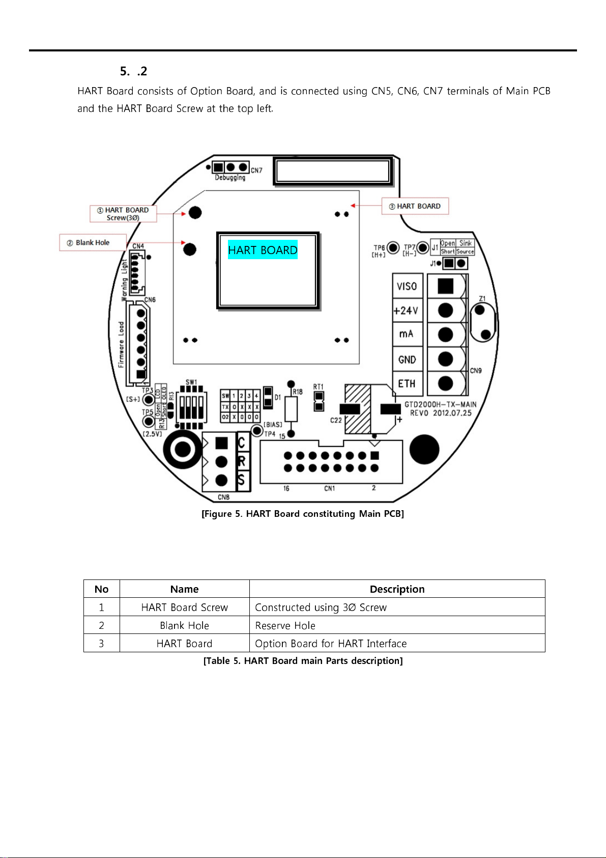
5.2.2. HART Board configuration
HART Board consists of Option Board, and is connected using CN5, CN6, CN7 terminals of Main CB
and the HART Board Screw at the top left.
[Figure 5. HART Board constituting Main PCB]
No Name Description
1 HART Board Screw Constructed using 3Ø Screw
2 Blank Hole Reserve Hole
3 HART Board Option Board for HART Interface
[Table 5. HART Board main Parts description]
HART BOARD

5.3. Main PCB terminal description and wiring method
If you remove the Display art, there is the Terminal Block under the Main CB as shown in the
following Figure 6. The Terminal Block can be removed from Main CB by holding and pulling upward
by hand. Unscrew the 5 terminal set screws above the separated
Terminal Block CN9 (VIS, +, mA, -,
ETH) Connector
counter-clockwise with a
Θ screwdriver; connect DC18-24V power to +, -; connect
Signal Cable to mA; tighten the terminal set screws clockwise to keep the terminals in place; and insert
it like before the removal.
[Figure 6. CN9 Terminal structure]
No CB Silk in Name
Description
4~20mA Source Drive
(J1 Jumper ON)
4~20mA Sink Drive
(J1 Jumper OFF)
1 VISO VIS N.C 4~20mA Sink In(+)
2 +24V + +24V / OWER (+)
3 mA mA 4~20mA Source Out 4~20mA Sink Out(-)
4 GND - GND / OWER (-)
5 ETH ET EARTH
[Table 6. CN9 connector description]
Note1) Be sure to use CVVS or CVVSB 1.5sq↑ Shield Cable before Terminal construction.
Note2) Fasten Terminals based on +24V of 2Pin to connect the 4Pin Terminal of existing
conventional GTD2000-Tx.
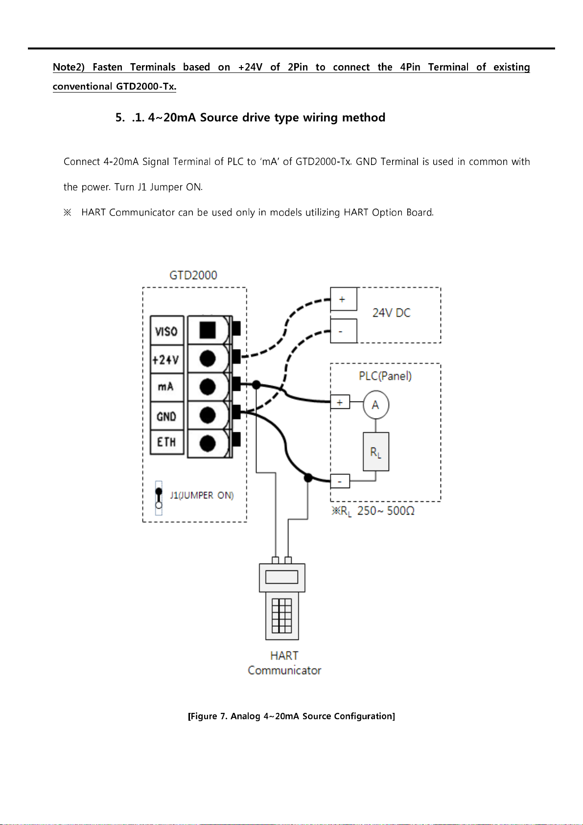
5.3.1. 4~20mA Source dri e type wiring method
Connect 4-20mA Signal Terminal of LC to ‘mA’ of GTD2000-Tx. GND Terminal is used in common with
the power. Turn J1 Jumper ON.
※
HART Communicator can be used only in models utilizing HART Option Board.
[Figure 7. Analog 4~20mA Source Configuration]

5.3.2. 4~20mA Sink dri e type wiring method
Connect 4-20mA Sink Output (+) Terminal of LC to VISO Terminal; and (-) Terminal to ‘mA’ Terminal.
Turn J1 Jumper OFF.
※
HART Communicator can be used only in models utilizing HART Option Board.
[Figure 8. Analog 4~20mA Sink Configuration]

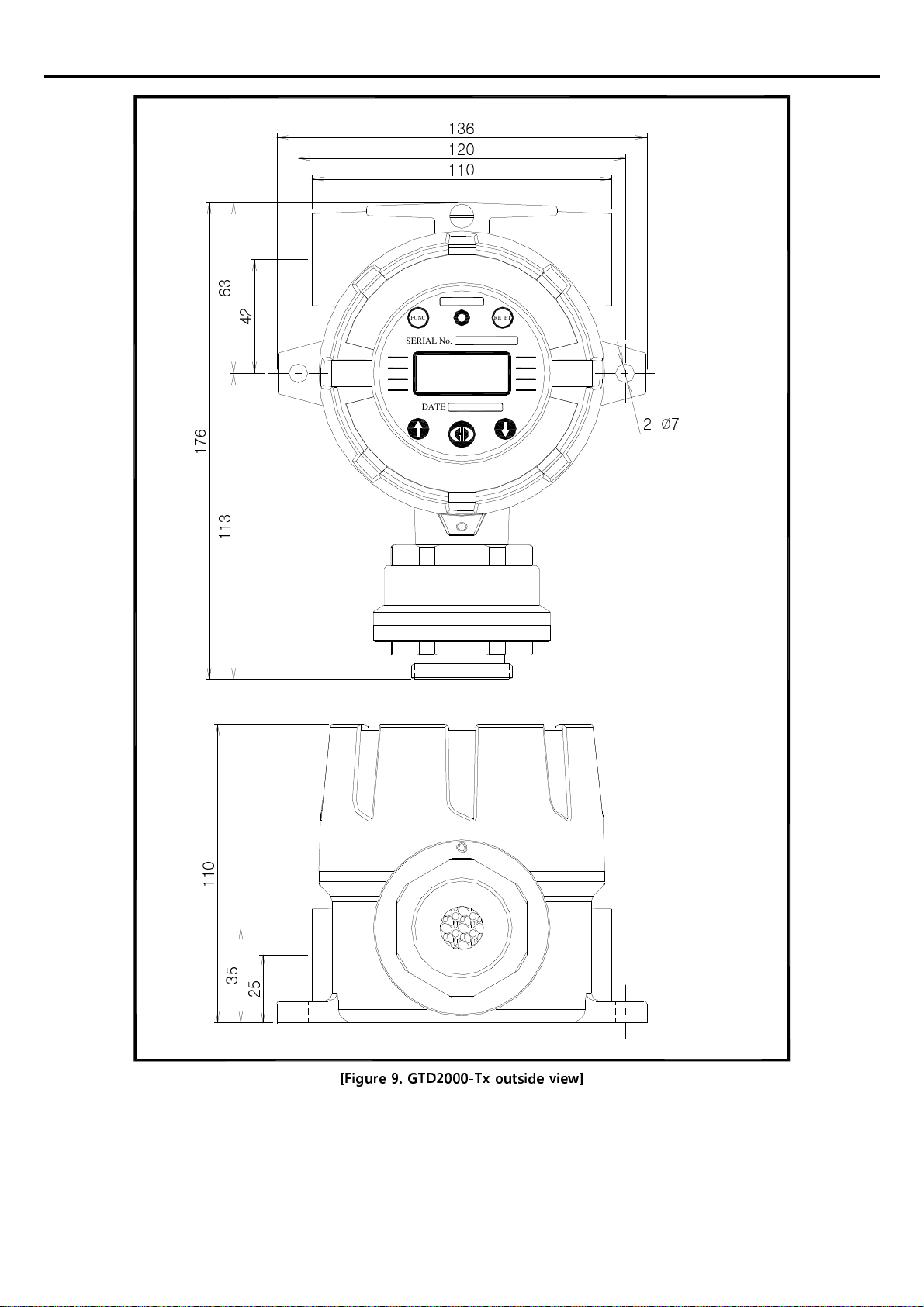
6. Standard Type outside view and Dimensions
1
1
3
2
5
3
5
1
1
0
110
120
136
4
2
6
3
1
7
6
2-
Ø
7
RESET
SERIAL No.
DATE
FUNC
[Figure 9. GTD2000-Tx outside view]
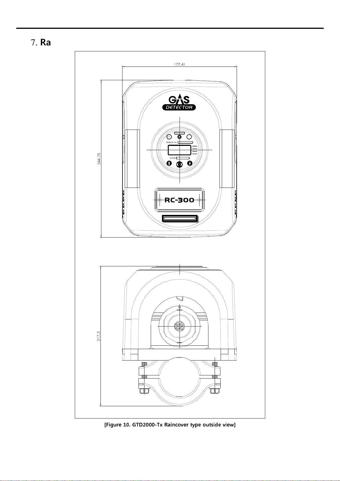
7. Raincover type: Outside view and Dimensions
2
4
4
.
7
5
177.41
2
1
7
.
5
RESET
SERIAL No.
DATE
FUNC
[Figure 10. GTD2000-Tx Raincover type outside view]
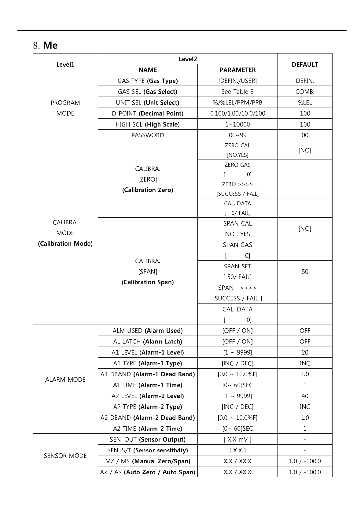
8. Menu Configuration Table
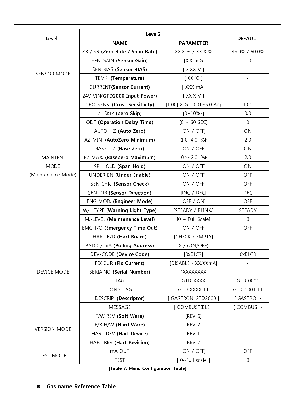
evel1 evel2 DEFAU T
NAME PARAMETER
ROGRAM
MODE
GAS TY E
(Gas Type)
[DEFIN./USER] DEFIN.
GAS SEL
(Gas Select)
See Table 8 COMB.
UNIT SEL
(Unit Select)
%/%LEL/ M/ B
%LEL
D- OINT
(Decimal Point)
0.100/1.00/10.0/100 100
HIGH SCL
(High Scale)
1~10000 100
ASSWORD 00~99 00
CALIBRA.
MODE
(Calibration Mode)
CALIBRA.
[ZERO]
(Calibration Zero)
ZERO CAL
[NO,YES]
[NO]
ZERO GAS
[ 0]
ZERO >>>>
[SUCCESS / FAIL]
CAL. DATA
[ 0/ FAIL]
CALIBRA.
[S AN]
(Calibration Span)
S AN CAL
[NO , YES] [NO]
S AN GAS
[ 0]
S AN SET
[ 50/ FAIL] 50
S AN >>>>
[SUCCESS / FAIL ]
CAL. DATA
[ 0]
ALARM MODE
ALM USED
(Alarm Used)
[OFF / ON] OFF
AL LATCH
(Alarm atch)
[OFF / ON] OFF
A1 LEVEL
(Alarm-1 evel)
[1 ~ 9999] 20
A1 TY E
(Alarm-1 Type)
[INC / DEC] INC
A1 DBAND
(Alarm-1 Dead Band)
[0.0 ~ 10.0%F] 1.0
A1 TIME
(Alarm-1 Time)
[0~ 60]SEC 1
A2 LEVEL
(Alarm-2 evel)
[1 ~ 9999] 40
A2 TY E
(Alarm-2 Type)
[INC / DEC] INC
A2 DBAND
(Alarm-2 Dead Band)
[0.0 ~ 10.0%F] 1.0
A2 TIME
(Alarm-2 Time)
[0~ 60]SEC 1
SENSOR MODE
SEN. OUT
(Sensor Output)
[ X.X mV ] -
SEN. S/T
(Sensor sensitivity)
[ X.X ] -
MZ / MS
(Manual Zero/Span)
X.X / XX.X 1.0 / -100.0
AZ / AS
(Auto Zero / Auto Span)
X.X / XX.X 1.0 / -100.0
evel1
evel2 DEFAU T
NAME PARAMETER
SENSOR MODE
ZR / SR
(Zero Rate / Span Rate)
XX.X % / XX.X % 49.9% / 60.0%
SEN GAIN
(Sensor Gain)
[X.X] x G 1.0
SEN BIAS
(Sensor BIAS)
[ X.XX V ] -
TEM .
(Temperature)
[ XX ‘C ] -
CURRENT
(Sensor Current)
[ XXX mA] -
24V VIN
(GTD2000 Input Power)
[ XX.X V ] -
MAINTEN.
MODE
(Maintenance Mode)
CRO-SENS.
(Cross Sensitivity)
[1.00] X G , 0.01~5.0 Adj 1.00
Z- SKI
(Zero Skip)
[0~10%F] 0.0
ODT
(Operation Delay Time)
[0 ~ 60 SEC] 0
AUTO – Z
(Auto Zero)
[ON / OFF] ON
AZ MIN.
(AutoZero Minimum)
[1.0~4.0] %F 2.0
BASE – Z
(Base Zero)
[ON / OFF] ON
BZ MAX.
(BaseZero Maximum)
[0.5~2.0] %F 2.0
S . HOLD
(Span Hold)
[ON / OFF] ON
UNDER EN
(Under Enable)
[ON / OFF] OFF
SEN CHK.
(Sensor Check)
[ON / OFF] OFF
SEN-DIR
(Sensor Direction)
[INC / DEC] DEC
ENG MOD.
(Engineer Mode)
[OFF / ON] OFF
W/L TY E
(Warning ight Type)
[STEADY / BLINK.] STEADY
M.-LEVEL
(Maintenance evel)
[0 ~ Full Scale] 0
EMC T/O
(Emergency Time Out)
[ON / OFF] OFF
DEVICE MODE
HART B/D
(Hart Board)
[CHECK / EM TY] -
ADD / mA
(Polling Address)
X / (ON/OFF) -
DEV-CODE
(Device Code)
[0xE1C3] 0xE1C3
FIX CUR
(Fix Current)
[DISABLE / XX.XXmA] -
SERIA.NO
(Serial Number)
*XXXXXXXX -
TAG GTD-XXXX GTD-0001
LONG TAG GTD-XXXX-LT GTD-0001-LT
DESCRI .
(Descriptor)
[ GASTRON GTD2000 ] [ GASTRO >
MESSAGE [ COMBUSTIBLE ] [ COMBUS >
VERSION MODE
F/W REV
(Soft Ware)
[REV 6] -
E/X H/W
(Hard Ware)
[REV 2] -
HART DEV
(Hart Device)
[REV 1] -
HART REV
(Hart Revision)
[REV 7] -
TEST MODE mA OUT [ON / OFF] OFF
TEST [ 0~Full scale ] 0
[Table 7. Menu Configuration Table]
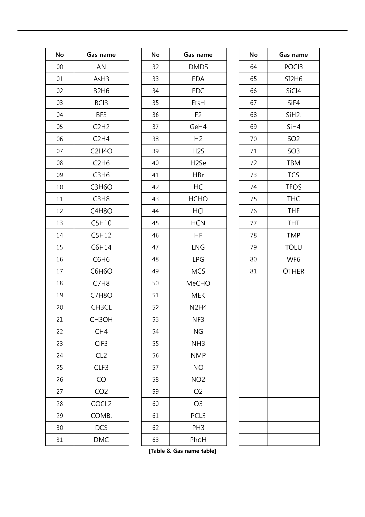
※
Gas name Reference Table
No Gas name No Gas name No Gas name
00
AN
32
DMDS
64
POCl3
01
AsH3
33
EDA
65
SI2H6
02
B2H6
34
EDC
66
SiCl4
03
BCl3
35
EtsH
67
SiF4
04
BF3
36
F2
68
SiH2.
05
C2H2
37
GeH4
69
SiH4
06
C2H4
38
H2
70
SO2
07
C2H4O
39
H2S
71
SO3
08
C2H6
40
H2Se
72
TBM
09
C3H6
41
HBr
73
TCS
10
C3H6O
42
HC
74
TEOS
11
C3H8
43
HCHO
75
THC
12
C4H8O
44
HCl
76
THF
13
C H10
45
HCN
77
THT
14
C H12
46
HF
78
TMP
15
C6H14
47
LNG
79
TOLU
16
C6H6
48
LPG
80
WF6
17
C6H6O
49
MCS
81
OTHER
18
C7H8
50
MeCHO
19
C7H8O
51
MEK
20
CH3CL
52
N2H4
21
CH3OH
53
NF3
22
CH4
54
NG
23
CiF3
55
NH3
24
CL2
56
NMP
25
CLF3
57
NO
26
CO
58
NO2
27
CO2
59
O2
28
COCL2
60
O3
29
COMB.
61
PCL3
30
DCS
62
PH3
31
DMC
63
PhoH
[Table 8. Gas name table]

9. Detector activation Flow and K Y operation
9.1. Sensor activation Flow
- Timeout of Level1 and Level2 is 10 seconds, and 1 hour in the Calibration and Test Mode of Level2.
[Figure 11. Sensor workflow]
9.2. Sensor KEY configuration and description
Item Name Description
FUNC Function Key
Sensor Mode entry function (more than 2 seconds of touch with Magnet-
bar in Measuring Mode). Entry to the next step of Level2 and storage of
setting value.
RESET Reset Key Moving back to the previous step before the entered LEVEL
↑
Up Key Change to the next step after LEVEL1, and plus change of Level2 setting.
↓
Down Key Change to previous step before LEVEL1; minus change of Level2 setting.
※
Sensor ower ON followed by simultaneous input of Reset Key and Function Key will result in Factory
Set in internal setting.
10. Initial status and Menu description
10.1. nitial operation status (Power On)
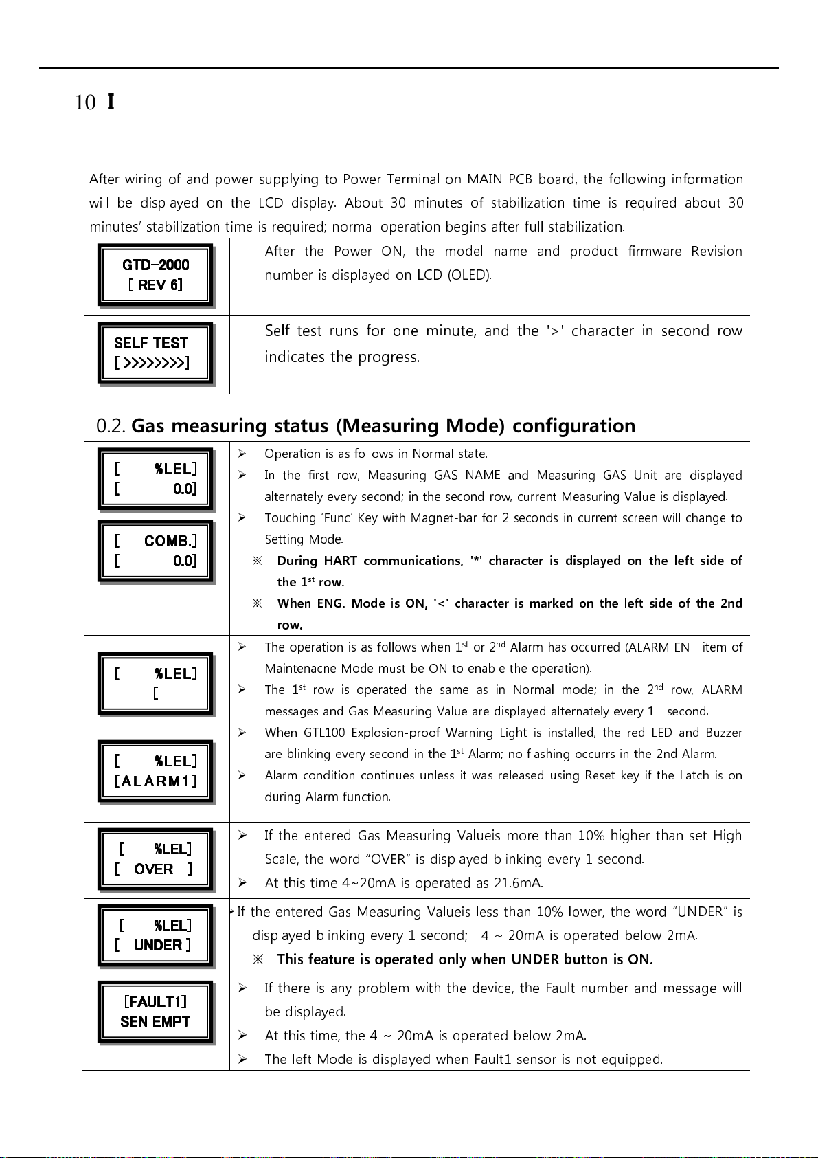
After wiring of and power supplying to ower Terminal on MAIN CB board, the following information
will be displayed on the LCD display. About 30 minutes of stabilization time is required about 30
minutes’ stabilization time is required; normal operation begins after full stabilization.
After the ower ON, the model name and product firmware Revision
number is displayed on
LCD (OLED).
Self test runs for one minute, and the '>' character in second row
indicates the progress.
10.2. Gas measuring status (Measuring Mode) configuration
Oper tion is s follows in Norm l st te.
In the first row, Me suring GAS NAME nd Me suring GAS Unit re displ yed
ltern tely every second; in the second row, current Me suring V lue is displ yed.
Touching ‘Func’ Key with M gnet-b r for 2 seconds in current screen will ch nge to
Setting Mode.
※
During HART communications, '*' character is displayed on the left side of
the 1
st
row.
※
When ENG. Mode is ON, '<' character is marked on the left side of the 2nd
row.
The oper tion is s follows when 1
st
or 2
nd
Al rm h s occurred (ALARM EN item of
M inten cne Mode must be ON to en ble the oper tion).
The 1
st
row is oper ted the s me s in Norm l mode; in the 2
nd
row, ALARM
mess ges nd G s Me suring V lue re displ yed ltern tely every 1 second.
When GTL100 Explosion-proof W rning Light is inst lled, the red LED nd Buzzer
re blinking every second in the 1
st
Al rm; no fl shing occurrs in the 2nd Al rm.
Al rm condition continues unless it w s rele sed using Reset key if the L tch is on
during Al rm function.
If the entered Gas Measuring Valueis more than 10% higher than set High
Scale, the word “OVER” is displayed blinking every 1 second.
At this time 4~20mA is operated as 21.6mA.
If the entered Gas Measuring Valueis less than 10% lower, the word “UNDER” is
displayed blinking every 1 second; 4 ~ 20mA is operated below 2mA.
※
This feature is operated only when UNDER button is ON.
If there is any problem with the device, the Fault number and message will
be displayed.
At this time, the 4 ~ 20mA is operated below 2mA.
The left Mode is displayed when Fault1 sensor is not equipped.
[FAULT1]
[FAULT1][FAULT1]
[FAULT1]
SEN EMPT
SEN EMPTSEN EMPT
SEN EMPT
[ %LEL]
[ %LEL][ %LEL]
[ %LEL]
[ UNDER ]
[ UNDER ][ UNDER ]
[ UNDER ]
[ %LEL]
[ %LEL][ %LEL]
[ %LEL]
[ OVER ]
[ OVER ][ OVER ]
[ OVER ]
[ %LEL]
[ %LEL][ %LEL]
[ %LEL]
[
[[
[ A LA R M1
ALAR M 1ALAR M 1
A LA R M1 ]
]]
]
[ %LEL]
[ %LEL][ %LEL]
[ %LEL]
[
[ [
[
[ COMB.]
[ COMB.][ COMB.]
[ COMB.]
[ 0.0]
[ 0.0][ 0.0]
[ 0.0]
[ %LEL]
[ %LEL][ %LEL]
[ %LEL]
[ 0.0]
[ 0.0][ 0.0]
[ 0.0]
SELF TEST
SELF TESTSELF TEST
SELF TEST
[
[[
[
>
>>
>>>>>>>>
>>>>>>>>>>>>>>
>>>>>>>]
]]
]
GTD
GTDGTD
GTD-
--
-2000
2000 2000
2000
[ REV 6]
[ REV 6][ REV 6]
[ REV 6]
Table of contents
Other GasTech Gas Detector manuals

GasTech
GasTech D-Guard2 User manual

GasTech
GasTech F-Guard-UV-IR-HD User manual

GasTech
GasTech G-Shield Fire User manual

GasTech
GasTech GTF220 User manual

GasTech
GasTech D-Guard2 User manual

GasTech
GasTech Cannonball 3 User manual

GasTech
GasTech F-GUARD UVIR User manual

GasTech
GasTech D-Guard User manual

GasTech
GasTech D-Guard2S User manual

GasTech
GasTech F-Guard-IR3-H2 User manual

Popular Gas Detector manuals by other brands


Honeywell
Honeywell Rae Systems MeshGuard Deployment guide

CPVan
CPVan CP-WG01W user guide

Riken Keiki
Riken Keiki SP-220 Series operating manual

RKI Instruments
RKI Instruments GX-86A instruction manual

FORENSICS DETECTORS
FORENSICS DETECTORS FD-91 quick start guide

ZyAura
ZyAura ZG906CMONP operating instructions


