GasTech F-Guard-UV-IR-HD User manual

t+61 8 6108 0000 einfo@gastech.com wgastech.com
USER MANUAL
UV/IR Flame Detector

Information
F-Guard-UV-IR-HDFlame Detector User Guide
Copyright © GASTECH AUSTRALIA PTY LTD All rights reserved.
The owner or authorized user of a valid copy of this manual may reproduce this publication for the
purpose of learning to use the specified equipment. No part of this publication may be reproduced or
transmitted for commercial purposes, such as selling copies of this publication or for providing paid for
support services.
The Gastech logo isa trademark of GASTECH AUSTRALIA PTY LTD,
registered inAustralia and other countries.
Every effort has been made toensure that the information in this manual is accurate. However,
GASTECH AUSTRALIA PTY LTD is not responsible for any inaccuracy or omission in this document. The
information in this document is subject to change without notice.
Legal Notice
Hardware, software or documentation is forbidden to be reproduced, transmitted, transcribed, stored in
a retrieval system or translated into any language or computer language, in any form or by any means.
While great efforts have been made toassure the accuracy andclarity of this document,
GASTECH AUSTRALIA PTY LTD assumes noliability resulting fromanyomissions in this document, or
from misuse of the information obtained herein. The information in this document has been carefully
checked and is believed to be entirely reliable with all of the necessary information included.
GASTECH AUSTRALIA PTY LTD reserves the right to make changes to any products
described herein to improve reliability, function, or design, and reserves the right to revise this
document and make changes from time to time in content hereof with no obligation to notify any
persons of revisions or changes. GASTECH AUSTRALIA PTY LTD does not assume any
liability arising out of the application or any use of any product or circuit described herein; neither does
it convey a license under its patent rights or the rights of others.

For more information & technical support: [email protected] iii
F-Guard UV-IR-HD User Manual
76-M-6010-02-02
Table of Contents
1. Introduction.................................................................................................................... 1
Key Features........................................................................................................................1
Model Number Description ..................................................................................................2
Internal tests .......................................................................................................................2
Product Overview ................................................................................................................3
Accessories..........................................................................................................................4
2. Installation ..................................................................................................................... 7
General Considerations ........................................................................................................7
Preparations for Installation...............................................................................................10
Required Tools...................................................................................................................10
Certification Instructions....................................................................................................10
Mounting the Tilt Mount....................................................................................................12
Mounting the detector.......................................................................................................13
Electrical Wiring.................................................................................................................14
Current Output (0-20mA) Wiring ........................................................................................16
4 Wire Relay Connection ....................................................................................................18
RS-485 Communication Network........................................................................................18
Cabling Recommendations .................................................................................................19
Earth/Ground Regime ........................................................................................................20
3. Configuration options ................................................................................................... 20
Sensitivity..........................................................................................................................22
Ultra-Fast Detection...........................................................................................................22
Alarm Delay.......................................................................................................................22
Alarm Latch .......................................................................................................................22
Enable Pre-Alarm 0-20mA ..................................................................................................22
Enable dirty window warning 0-20mA ................................................................................23
Auxiliary Relay...................................................................................................................23
Window Heater .................................................................................................................23

For more information & technical support: [email protected] iv
F-Guard UV-IR-HD User Manual
F130V0020.06
Video Settings....................................................................................................................23
Modbus Address ................................................................................................................23
Manual BIT – Alarm Output Test (Full loop test)..................................................................23
4. Operation ..................................................................................................................... 24
Output Signals ...................................................................................................................25
Testing...............................................................................................................................26
Flame Simulator.................................................................................................................26
5. Maintenance ................................................................................................................ 26
Cleaning Procedure ............................................................................................................26
6. Troubleshooting............................................................................................................ 27
7. Servicing ....................................................................................................................... 29
8. Communicator Software ............................................................................................... 29
9. Specifications................................................................................................................ 30
Fire Detection ....................................................................................................................30
Video Functionality ............................................................................................................30
Electrical Specifications ......................................................................................................30
Outputs .............................................................................................................................31
Mechanical Specifications ..................................................................................................31
Environmental Specifications .............................................................................................32
Product Labeling ................................................................................................................32
Approvals ..........................................................................................................................35
Electromagnetic Compatibility ...........................................................................................35
10. Performance.............................................................................................................. 35
F-Guard-UV-IR-HD-ASX1, F-Guard-UV-IR-HD-ASX2 (Standard model)...................................36
False Alarm Immunity ........................................................................................................38
11. Performance F-Guard-UV-IR-F-HD .............................................................................. 38
F-Guard-UV-IR-F-HD-ASX1, F-Guard-UV-IR-F-HD-ASX2 (Standard model) .............................39
False Alarm Immunity ........................................................................................................41
12. Ordering Information................................................................................................. 42
13.Warranty................................................................................................................... 43

For more information & technical support: info@gastech.com v
F-Guard UV-IR-HD User Manual
76-M-6010-02-02
Appendix A.......................................................................................................................... 44
List of Figures
Figure 1 - Front view of the FLS-UV-IR-HD(F).......................................................................................................3
Figure 2 - Rear view ofthe FLS-UV-IR-HD(F).......................................................................................................3
Figure 3 - Tilt mount .............................................................................................................................................4
Figure 4 - Weather Cover.....................................................................................................................................4
Figure 5 - Pole Mount ..........................................................................................................................................5
Figure 6 - Air Shield.............................................................................................................................................. 5
Figure 7 - Flame Simulator Kit..............................................................................................................................6
Figure 8 - FLS-FSIM-UV-IRFlame Simulator Front View ......................................................................................6
Figure 9 - Horizontal Field of View.......................................................................................................................8
Figure 10- Vertical Field of View .........................................................................................................................8
Figure 11: Tilt Mount Base - Plate View.............................................................................................................12
Figure 12: Tilt mount base – Side View..............................................................................................................12
Figure 13- Detector onTilt Mount – Side View.................................................................................................13
Figure 14– Terminal View .................................................................................................................................14
Figure 15– Source 4-Wire Scheme....................................................................................................................16
Figure 16– Sink 4-Wire Scheme ........................................................................................................................16
Figure 17– Source 3-Wire Scheme....................................................................................................................17
Figure 18– Sink 3-Wire Scheme ........................................................................................................................17
Figure 19- 4Wire Relay Connection .................................................................................................................18
Figure 20: RS-485 Networking ...........................................................................................................................19
List of Tables
Table 1: Terminal connections...........................................................................................................................15
Table 2: Detector Configuration Options...........................................................................................................21
Table 3: Sensitivity levels ...................................................................................................................................22
Table 4: Output Signals ......................................................................................................................................25

For more information & technical support: [email protected] 1
F-Guard UV-IR-HD User Manual
76-M-6010-02-02
1. Introduction
The F-Guard-UV-IR-HD flame detector provides ultra-fast response, high performance and reliable detection
of a large variety of fires including hydrocarbon fires (visible and non-visible), as well as hydrogen fires. The
detector addresses slow growing fires as well as fast eruptions of fire using improved UV-IR technology.
The detector operates in all weather and light conditions. The detector provides high-definition (HD) video
output of the monitored area with clear imaging of a fire event and of personnel at distances up to 100 ft
(30m) allowing rescuers to discover the exact situation before entering the hazardous area. It will
automatically record a video of a fire event (1 min pre-alarm/up to 3 mins post-alarm).
The integral HD quality video, with event recording, on top of the proven superior capabilities of UV-IR flame
detection together provide a very powerful safety tool to protect your personnel, plant and process. As
an option, the color HD camera can be replaced with a near IR camera if greater flame definition is needed.
This manual covers two UV/IR detector models:
1. F-Guard-UV-IR-HD: Hydrogen and hydrocarbons flame detection. UV radiation 0.18-0.26 micron
range. Spectrum response of IR radiation in the 2.5 - 3.5 micron range.
2. F-Guard-UV-IR-F-HD: Hydrocarbon flame detection. Spectrum response of IR radiation in the 4.0-5.0
micron range
Key Features
•High immunity: To false alarm
•Ultra-fast detection mode: Within 5 milliseconds for Hydrogen fireballs or explosions
•Hydrogen and hydrocarbons flame detection
•High sensitivity: Up to 100 ft. (30m) for a 1ft2 (0.1m2) n-heptane pan fire
•HD video output: With automatic HD video recording of fire events
•Option: Improved speed of response: (0.5s) for enclosed spare protection, like automotive
applications in compliance with NFPA 33 or printing presses and conveyors.
•Data/Event logger: Alarms, faults and other relevant events are logged to non-volatile memory
•Ethernet communication: In addition to the standard methods, such as 4-20mA and Modbus
•Built-in-Test (BIT): Automatic and manual internal self-test of window cleanliness and the overall
operation of the detector (for both IR and UV channels)
•Window heater: To avoid condensation and icing
•Tilt mounting bracket - for accurate detector positioning.
•UV and IR warning levels - 0-20mA - current output warning when elevated UV or IR radiation is
detected.
For more information & technical support: [email protected] 2
F-Guard UV-IR-HD User Manual
76-M-6010-02-02
Model Number Description
Model No are defined as follows:
F-Guard-UV-IR-F - A SX X
F-Guard-UV-IR - A SX X
1
Standard with RGB camera
2
Like model 1 with Near IR camera
5
Like model 1 but with a fast response mode that is design for, but
not limited to, automotive spray paint applications where
compliance with 0.5s response (per NFPA 33) is needed. With RGB
camera
1
M25
2
¾” NPT
1.2.1 Enhanced performance options
Option 5: Design for, but not limited to, automotive spray paint applications where compliance with 0.5 s
response (per NFPA 33) is needed
Internal tests
During normal operation, the flame detector performs self-tests of its optics, electronics and software. These
include a periodic BIT (Built-In-Test) in which the sensors and window cleanliness are tested. Any detected
fault is indicated as shown in Table 4 (in section 4). During “Dirty Window” fault the detection sensitivity is
significantly reduced, while “Fault” refers to critical faults which totally prevent flame detection.
For more information & technical support: [email protected] 3
F-Guard UV-IR-HD User Manual
76-M-6010-02-02
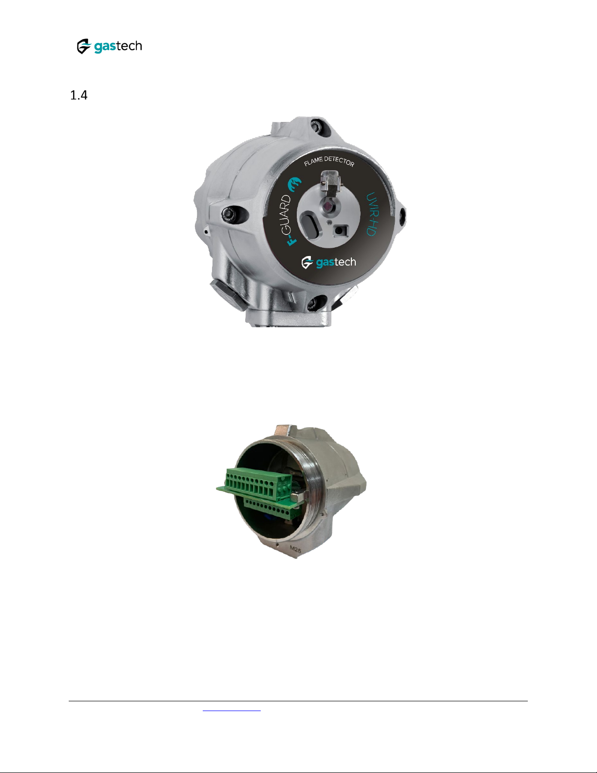
Product Overview
FIGURE 1-FRONT VIEW OF THE F-GUARD-UV-IR-HD (F)
FIGURE 2-REAR VIEW OF THE F-GUARD-UV-IR-HD (F)
For more information & technical support: [email protected] 4
F-Guard UV-IR-HD User Manual
76-M-6010-02-02
Accessories
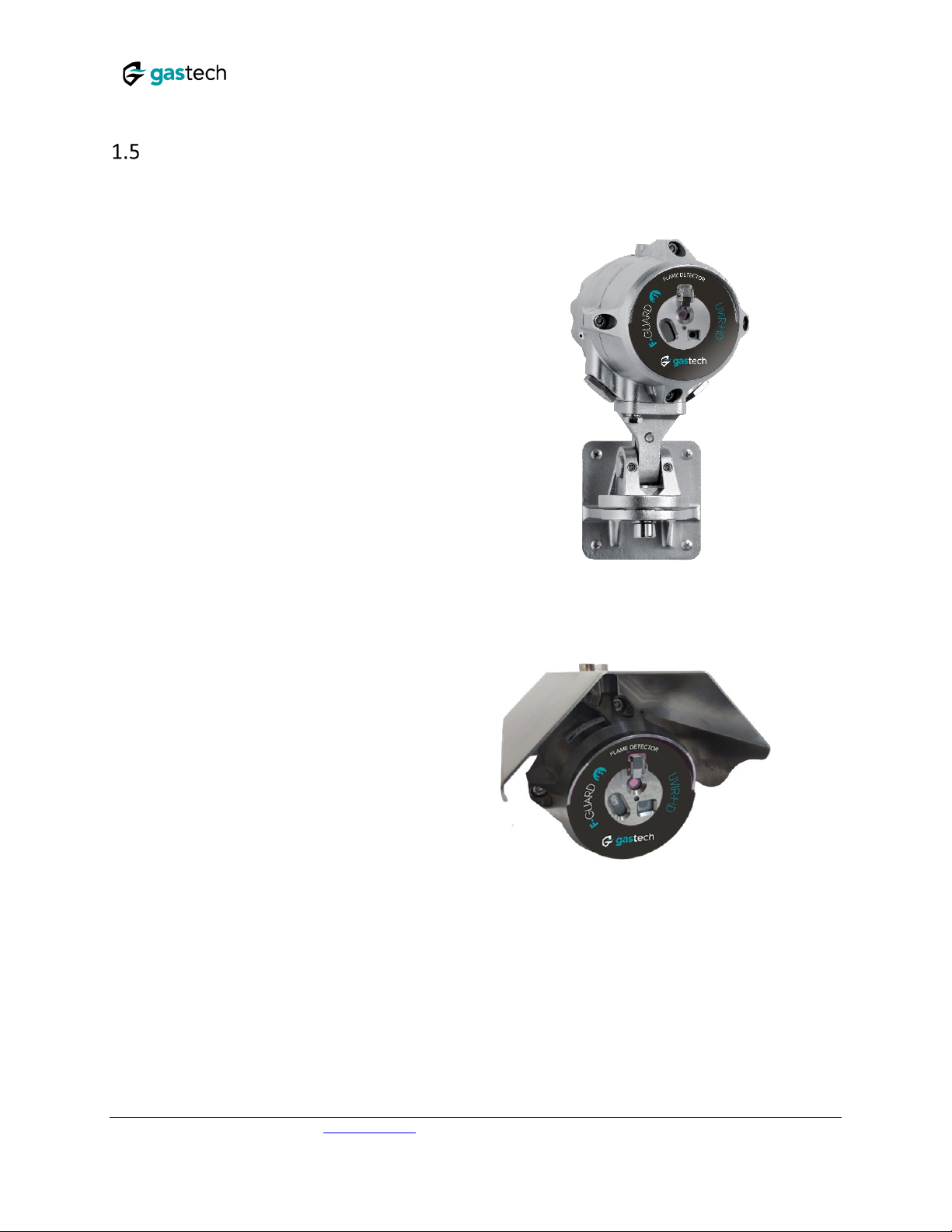
1.5.1 Mounting Bracket
The detector should be mounted using the
stainless-steel tilt mount part number 85-6000-
TMO-HD -TMO-S02. This allows the detector to
be securely attached to a wall, pole or other solid
surface using appropriate fixings. See sections2.5
and 2.6 for further details.
FIGURE 3-TILT MOUNT
1.5.2 Weather Cover
The weather cover P/N 85-6000-WC-SS-02protect
the detector from extreme weather conditions such
h
eat, rain and snow
FIGURE 4-WEATHER COVER
For more information & technical support: [email protected] 5
F-Guard UV-IR-HD User Manual
76-M-6010-02-02
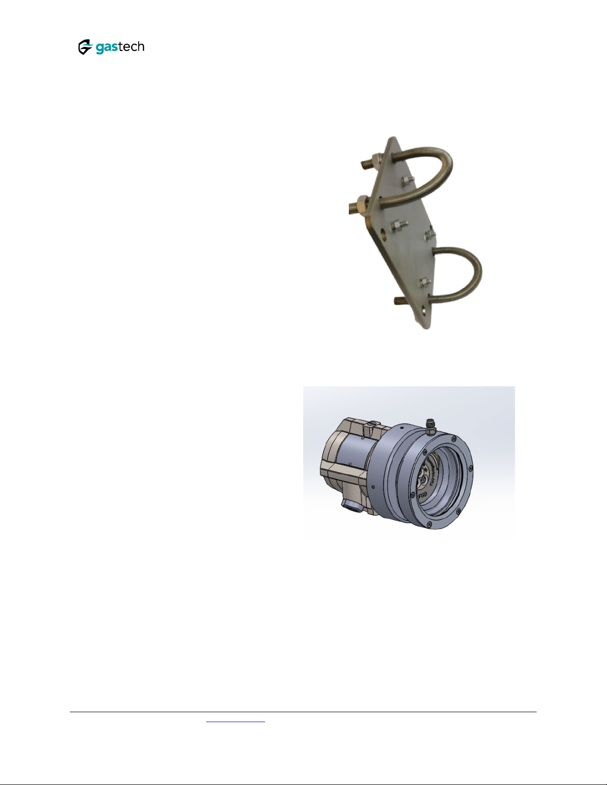
1.5.3 Pole mount
The pole mount enables the detectors to be
installed with its
tilt mount brackets. The pole
mount kit we supply are suitable for 2
-inch or 3-
inch poles. Part number FLS
-PMA-S23.
FIGURE 5-POLE MOUNT
1.5.4 Air shield
The air shield P/N FLS
-ASD-S02 allows installation of
flame detectors in harsh weather conditions where
they may be exposed to dust, sand, and other
particulate matter.
The connection point can be
mounted in the 3, 9 or 12 o’clock locations.
•
Air pressure source: Clean, dry, and oil-free air
•
Pressure: 2-3 bar /30-45 psi
•
Fitting: 7/16”—20UNF-2A
•
Operation temperature: -55°C to +85°C / -67°F to
+185°F
FIGURE 6-AIR SHIELD

For more information & technical support: [email protected] 6
F-Guard UV-IR-HD User Manual
76-M-6010-02-02
1.5.5 Flame Simulator
The F-Guard-UV-IR (F) may be tested using the FLS-
FSIM-UV-IR-KIT. The F-Guard flame simulator
family provides a fast and convenient means of
periodically testing the detector and control system
end-to-end. Maintenance costs can be reduced as
the detectors can be tested in situ without needing
a hot work permit.
F-Guard Flame Simulators emit UV and IR radiation
which simulates a fire to the detectors. The
simulators are lightweight, easy to use, with testing
distances of up to 21.3 ft. (6.5m) and capable of
more than 100 activations between battery
charging. F-Guard Flame Simulators are ATEX
approved for use in hazardous Zone 1, Zone 2, Zone
11, Zone 22 areas.
Each simulator kit contains a carrying case,
simulator, carrying strap, battery charger, user
manual, Allen key and a tool for removing the
simulator rear cover.
FIGURE 7-FLAME SIMULATOR KIT
FIGURE 8-FLS-FSIM-UV-IR FLAME SIMULATOR FRONT
VIEW

For more information & technical support: [email protected] 7
F-Guard UV-IR-HD User Manual
76-M-6010-02-02
2. Installation
This chapter does not attempt to cover all of the standard practices and codes of installation.
Rather, it emphasizes specific points of consideration and provides some general rules for
qualified personnel. You must always observe special safety precautions.
General Considerations
This section includes important information.
•To help obtain optimal performance, the detector should be aimed toward the center of
the hazard or area to be monitored and protected ("detection zone") and have, to the
extent that is required, an unobstructed view of the protected area. Whenever possible,
the detector face should be tilted (aimed) down at an angle to prevent the accumulation
of dust and dirt.
•Do not start an installation until the performance target, system configuration,
installation location and coverage considerations have been defined by the responsible
person.
To ensure optimal performance the following guidelines should be addressed:
Sensitivity
To determine the sensitivity level, the following issues should be considered:
•The size of the fire to be detected at the determined distance.
•The type of flammable fuel.
•Potential sources of false alarms that may be present (e.g., naked flames, hot process).
Spacing and Location
Consider the following factors when determining the number of detectors and their locations in
the protected area:
•The size and shape of the protected area
•The nature of the hazards, including materials stored or used and the protected objects
•The sensitivity of the detectors
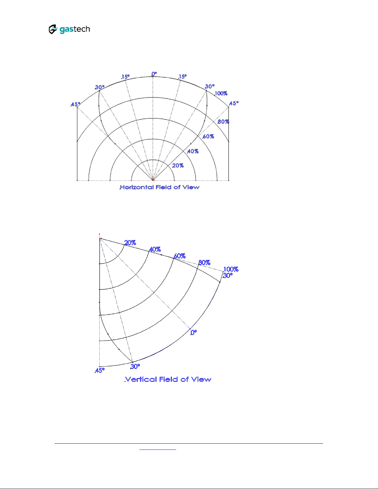
•If there are any obstructed lines of sight
•The field of view of the detectors (See Figure 9 and Figure 10)
For more information & technical support: [email protected] 8
F-Guard UV-IR-HD User Manual
76-M-6010-02-02
FIGURE 9-HORIZONTAL FIELD OF VIEW
FIGURE 10 -VERTICAL FIELD OF VIEW

For more information & technical support: [email protected] 9
F-Guard UV-IR-HD User Manual
76-M-6010-02-02
Environment
•Environmental conditions including but not limited to dust, snow or rain can reduce the
detectors sensitivity and require additional consideration.
Hot Work
•Arc welding should not be performed within 12 ft. (3.5m) of the detector. It is
recommended that the system be inhibited during welding operations in situations
where the possibility of a false alarm cannot be tolerated.
•Gas welding requires a system inhibit, since the gas torch is an actual fire.
•Arc welding rods can contain organic binder materials in the flux that burn during the
welding operation and are detectable by the device.
•Welding rods with clay binders do not burn and should not be detected. However, a
system inhibit is always recommended, since the material being welded may be
contaminated with organic substances (paint, oil, etc.) that will burn and may be of the
size that should be detected.
For more information & technical support: [email protected] 10
F-Guard UV-IR-HD User Manual
76-M-6010-02-02
Preparations for Installation
The installation must comply with national and local regulations and standards applicable to
flame detectors (e.g., NFPA 72) and all local and common engineering practices. It is
recommended to consult with the authority having jurisdiction.
Prior to installation:
•Make sure that you have all the components and tools required to complete the
detector installation readily available before beginning installation. In cases where you
cannot complete the installation in a single session, secure and seal the detectors and
conduits before leaving site.
•Use color-coded conductors or suitable wire markings or labels for the wiring. You may
use 14 to 17 AWG (2.5mm2to 1.0mm2) multi-strand wires for the site wiring. The
selection of wire gauge should be based on the number of detectors used on the same
line and the distance from the control unit, in compliance with specifications.
•Individually screen twisted pair cable is recommended for RS485 terminals.
•Use suitably rating wire for the application certification and temperatures.
Required Tools
The detector can be installed using the following tools:
Tool
Function
Hex. KEY 6 mm
Vertical alignment
Hex. KEY 10 mm
Horizontal alignment
Wrench 13 mm
Mounting the detector
Flat Screwdriver 6 mm
Ground screw connection
Flat screwdriver 3.5mm
Terminal connection
Certification Instructions
Warnings
•Do not open the detector, even when isolated, when flammable atmosphere present.
•The equipment may be used in hazardous areas with flammable gasses and vapors with
apparatus groups IIC, IIB and IIA and with temperature classes T1, T2, T3, T4 and T5. See
details of the explosion proof approvals in section 0.
•The equipment is certified for use in ambient temperatures in the range of -67°F to
+167°F (-55°C to +75°C) or -67°F to +185°F (-55°C to +85°C) and should not be used in
temperatures outside this range.
•Installation shall be carried out in accordance with the applicable code of practice by
suitably trained personnel.
•Inspection and maintenance of this equipment shall be carried out by suitably trained
personnel in accordance with the applicable code of practice.

For more information & technical support: [email protected] 11
F-Guard UV-IR-HD User Manual
76-M-6010-02-02
•If the equipment is likely to come into contact with corrosive and/or other harsh
substances, consult with the relevant technical persons to take suitable precautions to
prevent the detector from being adversely affected, thus ensuring that the type of
protection is not compromised.
•Harsh substances: For example, acidic liquids, gases, or solvents that may attack the
windows, metals, seals or polymeric materials.
•Suitable precautions: For example, regular checks as part of routine inspections or
establishing from the material’s data sheet that it is resistant to specific chemicals.
Specific conditions for use
•The equipment is not intended to be repaired by the user. Repair of this equipment shall
be carried out by the manufacturer in accordance with the applicable code of practice.
•The flame paths are not intended for repair. Contact the manufacturer if the flame
paths are damaged.
•Consult the manufacturer for genuine replacement cover and housing to connection box
fasteners. M6x1x18 Hexagonal Socket head fasteners with a minimum of ISO 4762
Grade A4 Class 80 are acceptable alternatives.
•One suitably certified stopping plug is supplied with the detector.
•The external earthing connection consists of cable lug with M5x10 stainless steel screw,
the terminals is suitable for connection of a wire of at least 4mm2 /12AWG.
•The internal terminals are suitable for connection of a wire equal to or greater than the
power input wiring and at a minimum of 1mm2/ 17AWG conductor.

For more information & technical support: [email protected] 12
F-Guard UV-IR-HD User Manual
76-M-6010-02-02
Mounting the Tilt Mount
The tilt mount enables the detector to be rotated up to 45 degrees (horizontal/vertical) in all
directions. The following installation instructions show how to use it to support the detector
from below (the preferred method).
To install the tilt mount:
a) Mount the tilt mount base (Figure 11: Tilt Mount Base - Plate View) to a solid structure using
four suitable fixings through the four 7mm (0.28") diameter holes. Four captive screws with
spring washers are provided in the tilt mount.
Figure 11: Tilt Mount Base - Plate View
Figure 12: Tilt mount base – Side View
For more information & technical support: [email protected] 13
F-Guard UV-IR-HD User Manual
76-M-6010-02-02
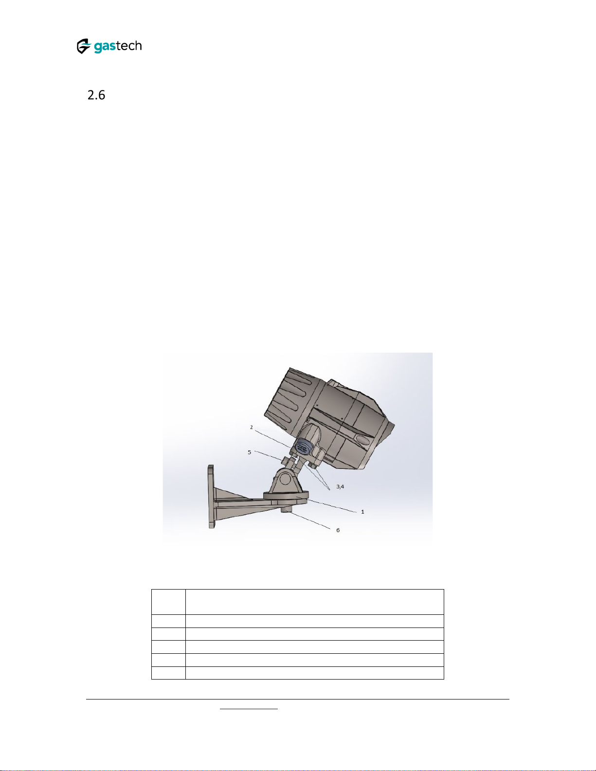
Mounting the detector
Use the following steps to connect the detector to the tilt mount, referring to Figure 13:
a) Place the detector, with its cable/conduit entries pointing down, on the holding plate of the
tilt mount (item 2).
b) Secure the detector to the plate using the two hex screws and spring lock washers (items 3
and 4).
c) Loosen the locking screws (Items 5 and 6) in such a way that enables you to rotate the
detector.
d) Point the detector towards the detection area and make certain that the view of the area is
unobstructed.
e) Secure the detector in that position by tightening the locking screws (Items 5 and 6) on the
tilt mount. (Make sure the detector is pointing in the correct direction).
The detector is now correctly mounted, aligned and ready for electrical connection. Please refer
to section 2.7 for wiring instructions, and section 3 for a description of the detector’s
configuration settings.
FIGURE 13 -DETECTOR ON TILT MOUNT –SIDE VIEW
ITEM
NO.
ITEM NAME
1
TILT MOUNT ASSEMBLY
2
HOLDING PLATE
3,4
MOUNTING HEX SCREWS M8 AND LOCK WASHERS
5
HEX SOCKET LOCKING SCREW M8
6
HEX SOCKET LOCKING SCREW M12

For more information & technical support: [email protected] 14
F-Guard UV-IR-HD User Manual
76-M-6010-02-02
Electrical Wiring
Warning
•The sensor module in the front half of the detector contains no serviceable components
and should never be opened. Opening will invalidate the warranty of the detector. The
terminal compartment at the back is the only part of the housing that should be opened
by the user.
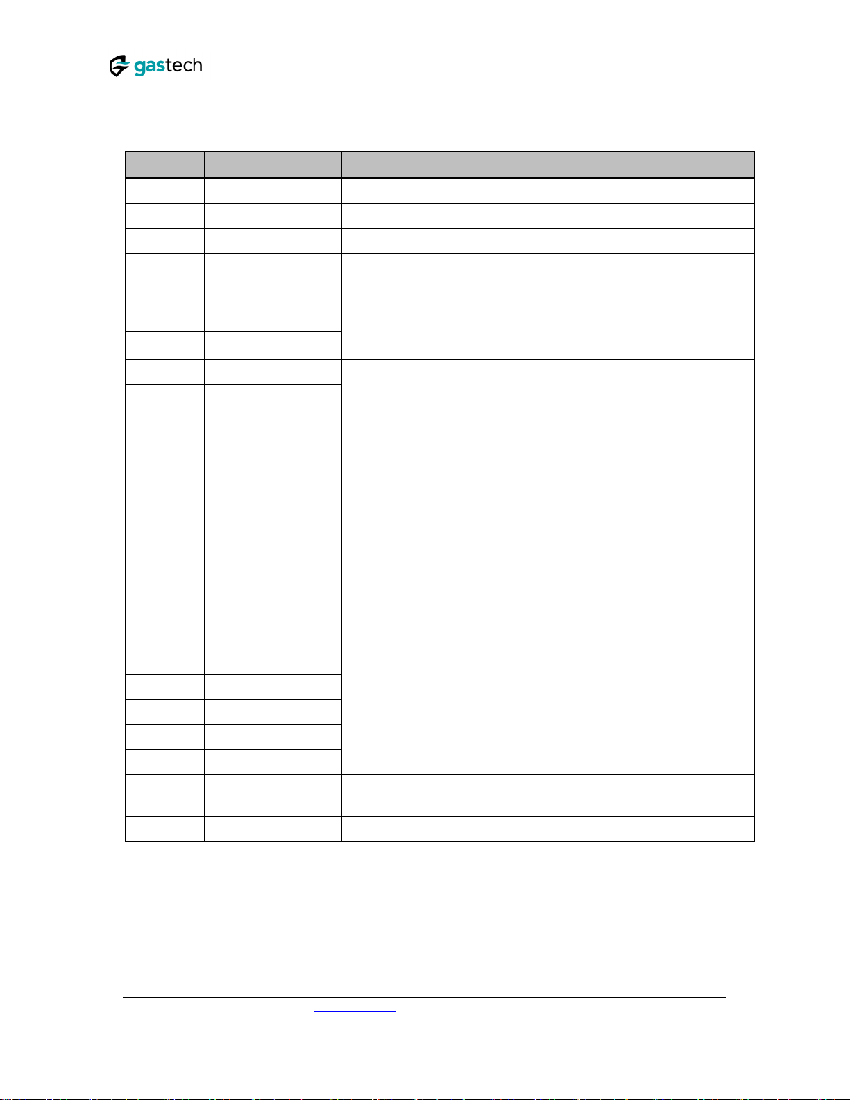
•The detector has 22 screw terminals as shown in the following figure and table:
F
IGURE
14
–
T
ERMINAL
V
IEW
For more information & technical support: [email protected] 15
F-Guard UV-IR-HD User Manual
76-M-6010-02-02
TABLE 1: TERMINAL CONNECTIONS
Pin #
Function
Description
Ground Ground (earth) Connected to a screw on the housing exterior.
1 24 VDC (+) Power supply (18-32 VDC)
2 24 VDC (-) Power supply return (0V)
3 0-20mA+ (In)
This output is used for analog 0-20 mA current output
4 0-20mA- (out)
5 Fault Relay A SPST contact relay, that is energized (closed) when the detector is in
normal operation and opens in case of fault.
6 Fault Relay COM
7 Alarm Relay (NO) A normally open SPST contact relay, that is open in normal operation,
and closed when fire is detected. This relay can be configured to latch
as described in section (3.4).
8 Alarm Relay COM
9 Analog Video +
Composite (analog) video output
10 Analog Video -
A1 Auxiliary Relay NO A normally open SPST contact relay with B1, that is open in normal
operation, and closed according to the configuration used.
11 24 VDC (+) Power supply (18-32 VDC)
12 24 VDC (-) Power supply return (0V)
13 Manual BIT activation
14 RS 485 (+)
15 RS 485 (-)
16 Ethernet TX+
The manual BIT (built-in test) can be initiated by momentarily short
circuiting this terminal and one ofthe “24 VDC (-)” terminals (2 or 12)”.
See 3.11 Manual BIT – Alarm Output Test for more details.
RS-485 Modbus communication (used by the “Gastech
Communicator” software)
Ethernet communication, used for digital video (with ONVIF profile S
protocol)
17 Ethernet TX-
18 Ethernet RX+
19 Ethernet RX-
20 Shield This terminal should be left connected to the housing internal ground
screw.
B1 Auxiliary Relay COM See A1 terminal
This manual suits for next models
1
Table of contents
Other GasTech Gas Detector manuals

GasTech
GasTech D-Guard2 User manual

GasTech
GasTech Cannonball 3 User manual

GasTech
GasTech GTF220 User manual

GasTech
GasTech G-Shield Fire User manual

GasTech
GasTech D-Guard2 User manual

GasTech
GasTech D-Guard2S User manual

GasTech
GasTech D-Guard User manual

GasTech
GasTech GTD2000-Tx User manual

GasTech
GasTech F-GUARD UVIR User manual

GasTech
GasTech F-Guard-IR3-H2-HD User manual


