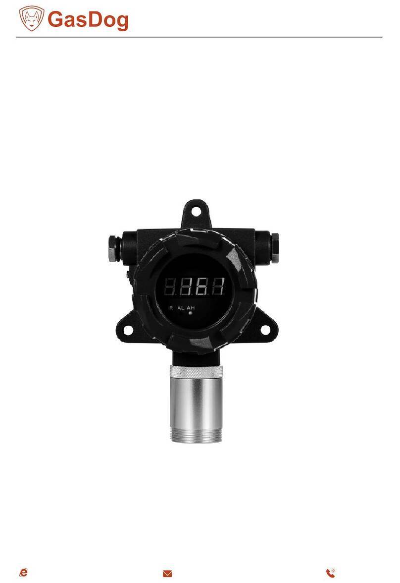
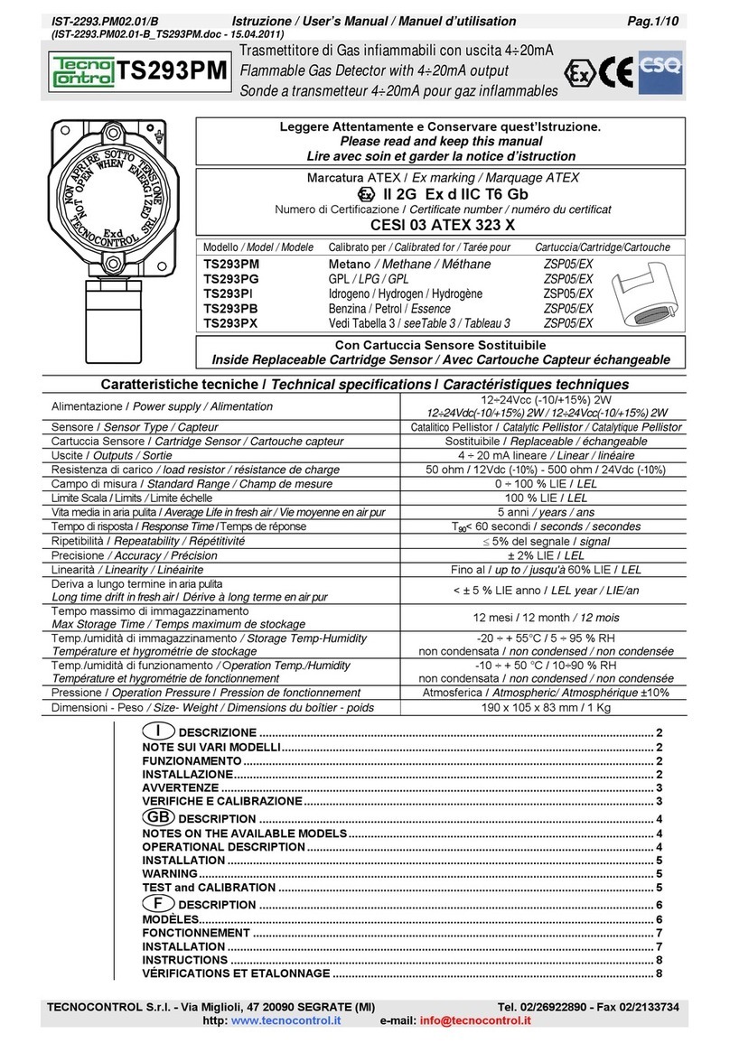
GasTech D-Guard User manual

D‐GuardTM
DigitalGuard
IntrinsicallySafeIntelligentGasDetector
PartNumber65‐1010xxx
ManualRevisionv2.08(updated5June2009)


TableofContents
1Introduction ............................................................................................................................................... 6
1.1 Features................................................................................................................................................ 6
2Installation ................................................................................................................................................. 7
2.1 Mounting .............................................................................................................................................. 7
2.2 OpeningTheEnclosure ......................................................................................................................... 8
2.3 Wiring ................................................................................................................................................. 10
2.3.1 ConnectiontoController ............................................................................................................. 10
2.3.2 ConnectiontoBarriers................................................................................................................. 11
2.3.3 OptionalRelayBoard ................................................................................................................... 14
2.4 Operation............................................................................................................................................ 17
3AdvancedSetup........................................................................................................................................ 18
3.1 ChangingthePCBorSensor ................................................................................................................ 18
3.2 PCBJumpersandCalibration............................................................................................................... 22
3.2.1 IsolateMode................................................................................................................................ 22
3.2.2 Normal/InvertJumper ................................................................................................................. 23
3.2.3 SensorBiasJumper...................................................................................................................... 24
3.2.4 SensorBiasVoltageAdjustmentTrimpot..................................................................................... 25
3.2.5 ShortingLinkJumper ................................................................................................................... 26
3.2.6 DisplayCurrentCalibrationTrimpot ............................................................................................ 27
3.2.7 OxygenLoadJumper ................................................................................................................... 27
3.3 SoftwareConfigurationandCalibration .............................................................................................. 28
3.3.1 Configuration............................................................................................................................... 28
3.3.2 Calibration ................................................................................................................................... 33
APPENDIXI. Troubleshooting.................................................................................................................... 38
APPENDIXII. FactorySetup ........................................................................................................................ 38
3.4 CalibratingZero/FullLoopCurrent ...................................................................................................... 38
APPENDIXIII. IECEXCertificate.................................................................................................................... 41
APPENDIXIV. SparePartsList...................................................................................................................... 44
APPENDIXV. Specifications ........................................................................................................................ 45

©2008GastechAustraliaPtyLtdPage2
PROPRIETARYSTATEMENT
GasTechAustraliaownsproprietaryrightsintheinformationdisclosedwithin.Byreceivingthisdocument,the
recipientagreesthatneitherthisdocumentnortheinformationdisclosedwithinnoranypartshallbe
reproducedortransferredtootherdocumentsorusedordisclosedtoothersformanufacturingorforany
otherpurposeexceptasspecificallyauthorisedinwritingbyGasTechAustralia.
COPYRIGHTSTATEMENT
Informationcontainedinthisdocumentisprotectedbycopyright.Nopartofthisdocumentmaybe
photocopied,reproduced,ortranslatedtoanotherprogramorsystemwithoutpriorwrittenauthorisation
fromGasTechAustralia.
TRADEMARKSTATEMENT
Protectedthroughuseand/orregistrationintheUnitedStatesandmanyforeigncountriesarethetrademarks
andservicemarksofGasTechAustralia.Theuseofthe®symbolindicatesregistrationintheUnitedStates
onlyandthe“TM”isinAustralia;registrationsmaynothavebeenissuedatpresentinothercountries.Allother
productnamesandlogosaretrademarksoftheirrespectiveowners.
DISCLAIMER
UndernocircumstanceswillGasTechAustraliabeliableforanyclaims,losses,ordamagesresultingfromor
arisingoutoftherepairormodificationoftheequipmentbyapartyotherthanGasTechAustraliaorits
authorisedservicerepresentatives,orbyoperationoruseoftheequipmentotherthaninaccordancewiththe
printedinstructionsprovidedbyGasTechAustraliaoriftheequipmenthasbeenimproperlymaintainedor
subjecttoneglectoraccident.Anyoftheforegoingwillvoidthewarranty.
REVISIONSTOMANUAL
Allinformationcontainedinthismanualisbelievedtobetrueandcorrectatthetimeofprinting.However,as
partofitscontinuingeffortstoimproveitsproductsandtheirdocumentation,GasTechAustraliareservesthe
righttomakechangesatanytimewithoutnotice.Anyrevisedcopiesofthismanualcanbeobtainedby
contactingGasTechAustralia.

Page3©2008GastechAustraliaPtyLtd
SERVICEPOLICY
GasTechAustraliamaintainsaninstrumentservicefacilityatthefactoryaswellasauthorisedservicefacilities
aroundtheworld.Shouldyourinstrumentrequireservice,youmaycontactustollfreeat1800999902within
Australiaonlyor61‐8‐9242‐1869,orvisitourwebsitewww.gastech.com.auforauthorisedservicelocations.
Fornon‐warrantyrepairs,youwillneedtoprovideapurchaseordernumber.Ifyouneedtosetalimittothe
repairscosts,statea“NottoExceed”figure.Ifyouneedaquotationbeforeyoucanauthoriserepaircosts,so
state,butunderstandthiswillincuradditionalcostsandmaydelayprocessingoftherepair.
Ifyouwishtosetalimittotheauthorisedrepaircost,statea“nottoexceed”figure.GasTechAustralia’spolicy
istoperformallneededrepairstorestoretheinstrumenttofulloperatingcondition,includingreactivationor
replacementofallout‐of‐warrantyelectrochemicalcells.
originalpacking)andanyspecial
instructions.Repairsarewarrantedfor90daysfromthedateofshipment.Sensorshaveindividualwarranties.
Alwaysincludeyouraddress,purchaseordernumber,shippingandbillinginformation,andadescriptionofthe
defectasyouperceiveit.Ifthisisthefirsttimeyouaredealingdirectlywiththefactory,youwillbeaskedto
providecreditreferences,prepay,orauthoriseCODshipment.
NOTE:GasTechAustraliaassumesnoliabilityforworkperformedbyunauthorisedservicefacilities.
Youmaysendtheunit,freightprepaid,to:GasTechAustraliaPtyLtd,24 Baretta Rd, Wangara, Western Australia 6065
Attn.:ServiceDepartment.Enclose the copy of your contact details.
Packtheinstrumentandallitsaccessories(preferablyinits

©2008GastechAustraliaPtyLtdPage4
WARRANTYSTATEMENT
1. ConsumershavethebenefitofconditionsandwarrantiesimpliedbytheTradePracticesAct1974(TPA)
andsimilarprovisionsofStateandTerritoryenactmentsandnothingintheseconditionsisintendedto
exclude,restrictormodifyanystatutoryobligationofGASTECHAUSTRALIAPTYLTD(Company)ifthat
cannotlawfullybeeffected.
2. ThiswarrantyrelatesonlytoEquipmentmanufacturedandservicessuppliedbytheCompany,itsrelated
corporationsandsubsidiaries.EquipmentoranypartthereofwhichisreturnedtotheCompany,
transportationprepaid,within15monthsfromthedateofdispatchfromtheCompany’spremisesor12
monthsfromthedateofshipmenttotheultimateuser(whicheveroccursfirst)andisfoundbythe
Company,afterexamination,tobedefectiveinworkmanshipormaterials,willbeeitherrepairedor
replacedasdeterminedbytheCompany,freeofcharge.Thetermsofthisparagraphapplyunlessstated
otherwiseinthisinstructionmanual.
3. Thiswarrantydoesnotapplyto:
a) replacementorrepairswhicharerequiredasaresultsofimproperinstallation,misuse,
maladjustmentmodificationorlackofroutinemaintenancebyothers;
b) itemssubjecttodeteriorationorconsumptioninnormalservice,thatis,thosewhichmustbe
cleaned,repairedorreplacedroutinelysuchas(butnotlimitedto)lamps,bulbsandfuses,pump
diaphragmsandvalves,absorbentcartridges,filterelementsandbatteries;or
c) goods,materialsorpartssuppliedormanufacturedbyunrelatedthirdpartiesandprovidedto
thePurchaseratthespecificrequestofthePurchaserandsuchgoods,materialsorpartswillbe
repairedorreplacedonlytotheextentoftheoriginalsupplierswarranty.
4. ShouldtheCompanybeliableforbreachofaconditionorwarranty(otherthanthepursuanttosection69
oftheTPA)impliedbyDivision2ofPartVoftheAct(otherthanthatimpliedbysection69oftheTPA)the
liabilityoftheCompanyforsuchbreachshall,subjecttosection68A(2)oftheTPA,belimitedtooneof
thefollowingasdeterminedbytheCompany.
a) thereplacementoftheEquipmentorthesupplyofequivalentEquipment‐,
b) thepaymentofthecostofreplacingtheEquipmentorofacquiringequivalentEquipment.
5. SubjecttoClauses2and4andanylegislationtothecontrary:
a) representativesandagreementsnotexpresslycontainedhereinshallnotbebindinguponthe
Companyasconditions,warrantiesorrepresentations;allsuchconditions,warranties,and
representationsonthepartoftheCompany,whetherexpressorimplied,statutoryorotherwise,
whethercollateralorantecedentorotherwiseareherebyexpresslynegativedandexcluded;
b) theCompanyshallbeundernoliabilitytothePurchaserforanyloss(includingbutnotlimitedto
lossofprofitsandconsequentialloss)orfordamagetopersonsorpropertyorfordeathorinjury
causedbyanyactoromission(includingnegligentactsoromissions)oftheCompanyorthe
Company’sagents,whereveroccurring,arisingfromthesubjectmatterofthisagreement;
c) thePurchasershallindemnifytheCompanyagainstanyclaimsmadeagainsttheCompanybyany
thirdpartyinrespectofanysuchloss,damage,deathorinjuryasissetoutinsub‐paragraphb)
hereof;thePurchaserfurtheragreestoindemnifytheCompanyagainstalllossesandexpenses
whichtheCompanymaysufferorincurduetothefailureofthePurchaserfullytoobserveits
obligationsunderthiscontract;and
d) nowarrantyisgivenandnoresponsibilityisacceptedbytheCompanytoensuretheEquipment
suppliedcomplieswithanystatutoryrequirementsrelatingtothemarketingofgoods.
CompliancewithsuchlegislationshallbethesoleresponsibilityofthePurchaser.
e) theCompanyspecificallydeniesanyliabilityfortheoverallperformanceofanyplantorthe
resultsofanyprocesswithwhichtheEquipmentisintegrated.

Page5©2008GastechAustraliaPtyLtd
MANUALCONVENTIONS
Thisinstrumentisdesignedtodetectoneormoreofthefollowing:flammablevapours,oxygencontentand/or
toxicgasandtogivewarningbeforetheyreachharmfullevels.Inordertoensurethatitwillwarnof
dangerousconcentrations,itisessentialthattheinstructionsinthismanual,particularlythoseconcerning
startup,operation,calibration,andmaintenance,beread,understood,andfollowed.
Noticesareusedinthisoperator’smanualtoalertyoutohazardousconditionstopersonorinstrumentandto
notifyyouofadditionalinformation.Thisoperator’smanualusesthefollowingnotices.
NOTE:Notifiesyouofadditionalinformation.
CAUTION:Notifiesyouofpotentialdamagetoequipment.
WARNING:Notifiesyouofpotentialdangerthatcanresultinpersonalinjuryordeath.

©2008GastechAustraliaPtyLtdPage6
1Introduction
GasTechAustraliaisproudtointroducethenextstepinfixedgasdetectionequipment.TheD‐GuardTM(Digital
Guard)isanintelligentgasdetectorwhichisdesignedaroundtheoperatorsrequirements.Easytocalibrate,
easytosetup,andhighlystable,fixed‐pointtoxicandOxygengasdetector.
TheD‐GuardTMisanindustrystandardtwowire24VDC4‐20mAdevice.
1.1 Features
•Nonintrusivecalibration
•Noalarmsduringcalibration
•OnePCBcardforallgasesdetected
•Notoolcalibration
•Sensordrifteliminationprogram
•Long‐termsensordeteriationdrifteliminationprogram
•Permanentbacklight
•Fail‐safemode
•Noncorrosivehousing
•Highimpacthousing
•Splashguardstandardsupply
•IP66design
•IECEXiaIICT4

Page7©2008GastechAustraliaPtyLtd
2Installation
WARNING:Performallinstallationproceduresinafreshairenvironment(knowntobefreeof
combustibleandtoxicgasandhavingnormaloxygencontent).TheD‐GuardTMisnotinoperationasa
systemuntilthestartupprocedureiscomplete.
2.1 Mounting
NOTE:ThepackingslipindicatestheserialnumberofyourD‐GuardTM.Theserialnumberisalsoona
labelonthesideoftheD‐GuardTM.Pleaserecordtheserialnumberonthefrontofthismanual.
Theinstallationshouldbeintheareawithmostpotentialtodetectthegasasquicklyaspossible.Takenoteof
thegasdensityasthiswillhelpinfindingthebestlocationfortheD‐GuardTM.Forexample,heaviergaseslike
H2SwouldhavethesensormountedlowerthanforHydrogenwhichisalightergas.
Securelymounttheunittothewallusingwallplugsandscrews.Dimensionsofthetwomountingholesonthe
D‐Guardenclosureareshownbelow.

©2008GastechAustraliaPtyLtdPage8
2.2 OpeningTheEnclosure
Inorderforpowertobeconnectedinsidetheunit,theenclosuremustbeopened.
1. Removethe4housinglidscrews(4mmAlankey).Thescrewsareheldinwith“O”ringstostopthem
fallingoutandlosingthem.
2. Gentlyremovethelidmakingsurethatyoudon’tlosethe4lidscrewsorthelarge“O”ringthatseals
thelidtothebase.
3. Turnoverthelidtofindthegreenpowerconnector.
4mmHex
orAllan
Ke
y
screws
Screwretaining
“O”ring
Powerconnector

Page9©2008GastechAustraliaPtyLtd
4. Runthepowercablesviathegrommettothegreenconnectorasdescribedinthenextsection.
5. Oncethewiringiscomplete,confirmthatthehousingsealing“O”ringisfittedandingoodcondition.
6. Fitlidandtightenthe4screwsusinga4mmAllankeytighteningthehousingevenly.
Housing“O”ring
seal

©2008GastechAustraliaPtyLtdPage10
2.3 Wiring
TheD‐GuardTMsensorcanbeusedwithanystandard2wire,4to20mA24VDCcontroller.Typicalcontrollers
includetheGasTechAustraliaMicroRackTM.
LocatedonthePCB,bottomrightcornerthereisatwopinremovableplug.Ensurethepositiveandnegative
wiresareterminatedwiththecorrectpolarity,whichismarkedonthePCB.
2.3.1 ConnectiontoController
WhenconnectingaD‐GuardTMunittoacontrollersuchastheGasTech4100Rcontroller,followthepinoutsas
outlinedbelow.Otherthirdpartycontrollersarealsoconnectedinthesamemanner.
Removable2‐pinplug.
0VDCand+24VDC

Page11©2008GastechAustraliaPtyLtd
2.3.2 ConnectiontoBarriers
Intrinsicsafetybarriersaredevicesthatlimitthecurrent,voltage,andtotalenergydeliveredtoasensorina
hazardousareaorflammableenvironmentinordertopreventanexplosion.
Thebarriersdesignedtoprotectthesystemmustbemountedoutsideofthehazardousareainanarea
designatedasNon‐hazardousorsafeinwhichthehazardisnotandwillnotbepresent.
IfyouareutilizingtheD‐GuardTMinaHazardousenvironment,youwillneedtoselectanappropriateISbarrier.
Selectionofthetypeofbarrierrequiresconsiderationofthevoltagedropsthatoccurinthesystem.AstheD‐
Guardrequiresaminimumof12VDCtooperate,thevoltagedropsinthebarriersystem,controllerload
resistorandcablingcannotexceedthepowersupplyvoltageless12VDC.
WARNING:InstallersshouldconsulttheIntrinsicallySafeBarriermanufactureandrefertoIEC
IntrinsicallySafeSystemStandardIEC60079‐25:2003orAS/NZS60079.25:2004beforeselectinga
suitablebarrier.
AD‐GuardoperatedwithoutabarrierwillrequiretheD‐Guardtobeinspectedbythemanufacture
toconfirmthatnoneofthesafetycomponentshavebeendamaged.

©2008GastechAustraliaPtyLtdPage12
GasTechrecommendtheGasTech57‐9010‐02barrier(KFD2‐STC4‐Ex1)formostsystems.Thisbarrierwillwork
onallcontrollersat24VDC.
WiringoftheGasTech57‐9010‐02barrierisasfollows:

Page13©2008GastechAustraliaPtyLtd
AsecondbarrierthatcanbeusedistheGasTech57‐9010‐01(MTL7787+).Thisbarriermustonlybeusedin
conjunctionwiththeGasTech4100Rcontrollercard,asthe4100Rcardhas100Ωload.
WARNING:Ifyouusethisbarrieronanothercontrollerthatusesaloadabove100OhmstheD‐Guardwill
turnoffwhenitseeahighgasreading(>15mA)asthevoltdropoverthisbarrierisgreater.
WiringoftheGasTech57‐9010‐01barrierisasfollows:

©2008GastechAustraliaPtyLtdPage14
2.3.3 OptionalRelayBoard
TheD‐GuardTMcanbeorderedwithanoptionalrelayboard(Partnumber:65‐1011‐xxx)whichallowstheD‐
GuardTMtooperateasaindependentunit.
WARNING:IftheD‐Guardisusedwiththerelayboard,theunitisnolongerIntrinsicallySafe,evenif
usedinconjunctionwithanISbarrier.
TheimagebelowshowsvariousconnectorsontherelayPCB.
Thefunctionofthevariousconnectorsisasfollows:
FeatureDescription
24V Connectthistothepositivesideofthepowersupply.Suppliespowertotherelay
boardaswellastheD‐GuardTMmainPCB.
FB(feedback) Currentsourceloopoutput,forconnectiontoanexternalcontroller
0V Connectthistonegativesideofthepowersupply
DG+ Thisneedstobeconnectedtothe+connectorontheD‐GuardTMmainPCB.
DG‐Thisneedstobeconnectedtothe‐connectorontheD‐GuardTMmainPCB.
AL1LowAlarm ThisrelayisenergizedwhenAL1isactive.Thisalarmpointisadjustableinsoftwareas
describedinthenextsection.
AL2HighAlarm ThisrelayisenergizedwhenAL2isactive.Thisalarmpointisadjustableinsoftwareas
describedinthenextsection.
FaultRelay Thisrelayisnormallyenergized.Itbecomesde‐energizedwhenthereisasensor
failure,powerfailureorwhentheD‐GuardTMisinIsolatemode.
JumperThisjumperconnectstheFBand0Vlinestogether.ItallowstheD‐GuardTMmainPCB
tooperateinstandalonemodewhereasystemcontrollerisnotpresent
Connectionto
powersource
anda4‐20mA
loop(optional)
PowerforD‐GuardTM
mainPCB
AL1Low
Alarm
AL2High
Alarm
Fault
rela
y
Wireharness
toD‐GuardTM
mainPCB
Jumper

Page15©2008GastechAustraliaPtyLtd
CAUTION:Therelaycontactsareratedat5A@48VDCmax.Mainsconnectionisnotpermitted.
TheD‐GuardTMwithrelayoptionisnormallyusedinstandalonemode,howeveritcanstillbeconnectedback
toacontrollersuchastheGastech4100R.Thediagrambelowshowshowtheunitsarewiredtogether.
NOTE:Inthisconfiguration,thejumperontherelayPCBmustberemoved.
InternalConnectiondiagrams:
REMOVE Lk1
(Do not insert)
Connect to
+24VDC
Connectto
0VDC
D-Guard to Relay Board Connections
(Current loop output configuration)
ConnecttoPLCcurrentloop
input(currentsinkonly)

©2008GastechAustraliaPtyLtdPage16
Lk1 MUST BE
INSERTED
Connect to
+24VDC
Connect to
0VDC
D-Guard to Relay Board Connections
(Standalone configuration)

Page17©2008GastechAustraliaPtyLtd
2.4 Operation
CompletethefollowingprocedurestoplacetheD‐GuardTMintonormaloperation.
1. Completethemountingandwiringproceduresdescribedintheprevioussections
2. Completeallinstallationproceduresdescribedinthismanual
3. Verifythatallwiringconnectionsarecorrectandsecure
4. Checkpowerbeingsuppliedtotheunitiscorrect(24VDC)
5. Turnontheincomingpoweratthepowersource
NOTE:TheD‐GuardTMstartsupinawarm‐upIsolatedmodewiththemAlockedat3mAfor90seconds
whilethesensorstabilisedandtheD‐GuardTMprograminitialisesandcompletesaseriesoffunctiontests.
Afterthestartupprocedureandalltestsarecompletedifoperatingiswithintolerancethedisplaywillgointo
normaloperatingmode,themAwillbereleasedandthesystemwillthenbefunctioning.TheLCDscreen
showsthestatusofthesystem.
Gasreading
Unitof
measurement
Fullscale
value
Gasbeing
detected

©2008GastechAustraliaPtyLtdPage18
3AdvancedSetup
OneofthekeyfeaturesoftheD‐GuardTMisitsabilitytobeeasilyservicedandcalibratedinthefield.Theunit
willneedtobecalibratedand/orreconfiguredifyouareperforminganyofthefollowingtasks:
•ReplacingaPCB
•Replacingasensor
•Changingtoadifferentsensor
•Scheduledcalibrationormaintenance
•Reactivationafterprolongedshutdown
AllcalibrationvaluesarestoredintheD‐GuardTMnonvolatilememorybutasnomonitoringofthesensor
operationisperformedduringtheshutdownperiodthesensormighthavebeenpoisonedandmightnot
respondasexpected.
3.1 ChangingthePCBorSensor
1. Isolatethesensorbackatthecontrolpanelsoanopencircuitfaultwillnottriporcreateanyalarms.
2. Removethe4housinglidscrews(4mmAlankey).Thescrewsareheldinwith“O”ringstostopthem
fallingoutandlosingthem.
3. Gentlyremovethelidmakingsurethatyoudon’tlosethe4lidscrewsortheLarge“O”ringthatseals
thelidtothebase.
4mmHex
orAllan
Ke
y
screws
Screwretaining
“O”ring
Table of contents
Other GasTech Gas Detector manuals
GasTech
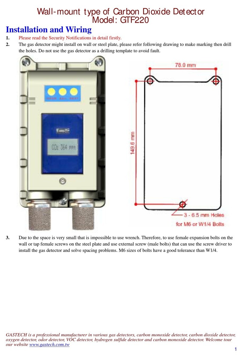
GasTech GTF220 User manual

GasTech
GasTech Cannonball 3 User manual

GasTech
GasTech D-Guard2S User manual

GasTech
GasTech G-Shield Fire User manual

GasTech
GasTech F-GUARD UVIR User manual

GasTech
GasTech F-Guard-UV-IR-HD User manual

GasTech
GasTech F-Guard-IR3-H2 User manual

GasTech
GasTech F-Guard-IR3-H2-HD User manual

GasTech
GasTech D-Guard2 User manual

GasTech
GasTech D-Guard2 User manual
