Gate Motors MyGate myAster Series User manual

REVISION 2019-2
automation Kit for swing gates
myAster
GateMotors: +44 (0)1202 744958 • Technical support: +44 (0)1202 725489
www.gatemotors.co.uk • Sales and Accessories: +44 (0)1202 717191
ENGLISH
Installation Manual
BY

REVISION 2019-2
KG
Use and installation of the product
must comply with Machinery
Directive 2006/42/CE.
Verify that the system is EN 124445
and EN 12453 standard compliant.
Installation must be carried out by
qualified personnel who are aware of
the associated potential hazards, and
are operating in full compliance with
current regulations.
General safety precautions
This manual contains important information for the safety of consumers.
An improper installation can result in serious injury to people and/or property.
Before beginning the installation it is absolutely necessary to read this manual in its entirety.
Save this manual for future consultation.
GateMotors: +44 (0)1202 744958 • Technical support: +44 (0)1202 725489
www.gatemotors.co.uk • Sales and Accessories: +44 (0)1202 717191
The myAster motor is designed to automate swing gates. The use
of this product for purposes other than those described above
and installation executed in a manner other than instructed in this
technical manual are prohibited.
All myAster systems are irreversible, therefore an electric lock is
not essential – but an electric lock is recommended for additional
security, or for use in areas exposed to high-winds. The electric
lock must be installed on the gate leaf that opens first and must
be connected with the terminals of the control unit.
If fitting an electric lock, remove all manual locks and bolts.
In the event of a power cut the gate motor can be released by
manual operation.
Use of the product must be restricted to its intended use. Any
other use is to be considered dangerous and therefore forbidden.
Do not allow children to play with the fixed command devices, or
in the gate’s area of operation. Keep any remote control devices
(i.e. transmitters) away from children.
Keep the gate and the gate opener regularly maintained. Use only
myGate or GateMotors supplied spare parts.
Users are strictly forbidden to carry out any changes on the gate
motor.
GateMotors is not liable for any damage resulting from improper,
wrongful or unreasonable use.
The use of this equipment must observe the safety standards in
force in the country where it is installed, as well as the standards
governing proper installation.
KG
KG
KG
KG
KG
KG
KG
KG
KG
KG
KG
KG
KG
Any lawn watering devices
must not wet the gate
motor from the bottom up.
There is sufficient
space for manual
release.
The opening of the automated
gate is not an entrapment
hazard with regards to any
surrounding fixed parts.
Intended use and application
PRE-INSTALLATION
CHECKLIST
Verify that the technical features
fit your installation needs.
The gate hinges are in
good condition and
are suitably lubricated.
The gate leafs
swing freely and are
clear of obstruction
The gate has mechanical
stops in both the open
and closed positions.
Always cut off the power
during the installation or
maintenance of any parts.
The gates are NOT on
either an upward
or downward slope.
KG
KG
KG
KG
KG
KG
KG
KG
KG
KG

REVISION 2019-2
Tools and xings
RECOMMENDED FIXINGS
(not included)
REQUIRED TOOLS
Brick
Screw and wall plug
Concrete
Concrete anchor
Metal pillar
Nut and bolt
Steel
Lock nut
Steel / Aluminium
Nut and bolt
Wood
Wood screw
RECOMMENDED
GATE LEAF FIXINGS
(not included)
GateMotors: +44 (0)1202 744958 • Technical support: +44 (0)1202 725489
www.gatemotors.co.uk • Sales and Accessories: +44 (0)1202 717191
myAster dimensions
50 mm
119 mm
169 mm
myAster 3 = 665 mm
myAster 4 = 765 mm
myAster 5 = 865 mm
myAster 6 = 965 mm
myAster 3 = 980 mm
myAster 4 = 1180 mm
myAster 5 = 1380 mm
myAster 6 = 1580 mm
TOP ELEVATION
SIDE ELEVATION CLOSED SIDE ELEVATION OPEN
88 mm

REVISION 2019-2
myAster 3 myAster 4 myAster 5 myAster 6
Power supply 24 Vdc 230 V ~ 50 Hz 24 Vdc 23 0V ~ 50 Hz 24 Vdc 230 v ~ 50 Hz 230 V ~ 50 Hz
Absorption 0,5-0,75 A 1.2 - 1.7 A 0,5-0,75 A 1.2 - 1.7 A 0,5-0,75 A 1.2 - 1.7 A 1.2 - 1.7 A
Motor power 50 W 280 W 50 W 280 W 50 W 280 W 280 W
Capacitor -- 8 µF -- 8 µF -- 8 µF 8 µF
Thermic protection -- 150° -- 150° -- 150° 150°
Maximum thrust 2500 2800 N 2500 2800 N 2500 N 2800 N 2800 N
IP level 44 44 44 44 44 44 44
Revolutions speed 1600 rpm 1400 rpm 1600 rpm 1400 rpm 1600 rpm 1400 rpm 1400 rpm
Leaf’s maximum length 2000 mm 2000 mm 2500 mm 2750 mm 3000 mm 3500 mm 4000 mm
Leaf’s maximum weight 275 Kg 350 Kg 250 Kg 350 Kg 150 Kg 250 Kg 250 Kg
Maximum opening 110º 110º 110º 110º 110º 110º 110º
90º opening time 15” 17” 20” 22” 25” 27” 32”
Duty cycle 80 % 40 % 80 % 40 % 80 % 40 % 40 %
GateMotors: +44 (0)1202 744958 • Technical support: +44 (0)1202 725489
www.gatemotors.co.uk • Sales and Accessories: +44 (0)1202 717191
Technical features
INWARD FACING
A
B
C
ED F G H
myAster Kit Contents (included)
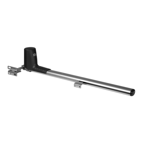
2 x Motors
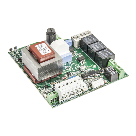
1 x Control Board (with in-built aerial)
2 x Wired Safety Photocells
2 x Radio Remotes
2 x Gate Fixing Brackets S3
2 x Pillar Fixing Brackets T1
2 x Manual Release Keys
2 x Fixing pins
A
B
C
D
E
G
F
H

REVISION 2019-2
GateMotors: +44 (0)1202 744958 • Technical support: +44 (0)1202 725489
www.gatemotors.co.uk • Sales and Accessories: +44 (0)1202 717191
Installing the motor
Motor positioning
Make sure there are mechanical stops (B) for opening and closing.
The motor has to be fitted keeping a height above ground of between 400 mm and 500 mm. If the gate
is particularly light, fit the motor as close as possible to the gate centerline. The motor should not be fitted
lower than 150 mm from ground level. And no more than 600 mm higher than ground level.
Centreline
min height = 150 mm
max height = 600 mm
Left motor Right motor
INWARD FACING
Check that the open position of the automated gate is not an entrapment hazard with regards
to any surrounding buildings or fixed objects and there is sufficient space for manual release.
INSTALLATION INSTRUCTION
SEQUENCE
1Thoroughly read sections: General safety
precautions, and Intended use and application.
2Check all the components.
3Identify the fixing points on the pillar and on
the gate.
4Verify measurement D.
5Adjust bracket T1 as needed.
6Fix the motor to the bracket T1
7Release the motor.
8Fix bracket S3 to the gate.
9Fix the motor ram to the bracket S3.
10 Position the cables as per the Wiring
installation overview.
11 Connect the control unit and all accessories.
12 Program the radio receiver.
13 Program the working times.

REVISION 2019-2
GateMotors: +44 (0)1202 744958 • Technical support: +44 (0)1202 725489
www.gatemotors.co.uk • Sales and Accessories: +44 (0)1202 717191
If the ideal scenario of
measurements Aand B(above)
is unachievable then refer to
the below tables to determine
the position and mounting hole
selection for bracket T1.
D200 mm 175 mm 150 mm 125 mm 100 mm 75 mm 50 mm 25 mm 0 mm
A140 mm 170 mm 200 mm 195 mm 190 mm 185 mm 210 mm 235 mm 260 mm
B150 mm 225 mm 200 mm 205 mm 210 mm 215 mm 190 mm 165 mm 140 mm
Bracket quota 50 mm 50 mm 50 mm 80 mm 110 mm 140 mm 140 mm 140 mm 140 mm
Minimum leaf length 1030 mm 1000 mm 980 mm 990 mm 990 mm 970 mm 970 mm 950 mm 930 mm
myAster 4
D225 mm 200 mm 175 mm 150 mm 125 mm 100 mm 75 mm 50 mm 25 mm
A225 mm 250 mm 245 mm 240 mm 235 mm 260 mm 285 mm 310 mm 335 mm
B275 mm 250 mm 255 mm 260 mm 265 mm 240 mm 215 mm 190 mm 165 mm
Bracket quota 50 mm 50 mm 80 mm 110 mm 140 mm 140 mm 140 mm 140 mm 140 mm
Minimum leaf length 1150 mm 1130 mm 1130 mm 1130 mm 1140 mm 1120 mm 1100 mm 1070 mm 1050 mm
myAster 5
D275 mm 250 mm 225 mm 200 mm 175 mm 150 mm 125 mm 100 mm 75 mm
A275 mm 300 mm 295 mm 290 mm 315 mm 310 mm 335 mm 360 mm 385 mm
B325 mm 300 mm 305 mm 310 mm 285 mm 290 mm 265 mm 240 mm 215 mm
Bracket quota 50 mm 50 mm 80 mm 110 mm 110 mm 140 mm 140 mm 140 mm 140 mm
Minimum leaf length 1300 mm 1240 mm 1280 mm 1260 mm 1260 mm 1270 mm 1240 mm 1220 mm 1200 mm
myAster 6
D150 mm 125 mm 100 mm 75 mm 50 mm 25 mm 0 mm
A100 mm 125 mm 150 mm 145 mm 140 mm 135 mm 160 mm
B200 mm 175 mm 150 mm 155 mm 160 mm 165 mm 140 mm
Bracket quota 50 mm 50 mm 50 mm 80 mm 110 mm 140 mm 140 mm
Minimum leaf length 880 mm 860 mm 840 mm 840 mm 850 mm 850 mm 830 mm
myAster 3
90º
Pillar bracket T1
How to determine xing dimensions
Position the bracket T1 using the measurement Aand Bas indicated
in the below table for an inward opening angle of 90° (pic E).
(pic E)
myAster 3 myAster 4 myAster 5 myAster 6
A150 mm 200 mm 250 mm 300 mm
B150 mm 200 mm 250 mm 300 mm
D125 mm (max.) 175 mm (max.) 225 mm (max.) 275 mm (max.)
(Table A)

REVISION 2019-2
GateMotors: +44 (0)1202 744958 • Technical support: +44 (0)1202 725489
www.gatemotors.co.uk • Sales and Accessories: +44 (0)1202 717191
Fix the pivot bracket T1 onto the pillar by welding or bolting (O
/13 mm bolts), making sure the measurements shown
in the previous table are met. Ensure to keep a minimum distance of 30 mm from the pillar edge as shown (pic H).
In cases of masonry pillars, use chemical or resin to secure the bolts into position. Brackets T1 are supplied in two
versions, left hand and right hand and match the according motor (see picture I). Fix the motor to bracket T1 and place
the pivot pin PR1 through the holes. Keep the pivot pin PR1 oriented downward (pic J).
Fixing pillar bracket T1
Gates xed on the edge/corner of a pillar
In this case the gate can be opened up to 120°. To achieve this, measurement Amust
be equal to or greater than measurement B(pic F).
Based on the figures shown on the previous page (Table A) – Ideally measurement B
(Pic F) will be decreased by the same amount as the Ameasurement is increased.
For example: If installing the myAster 3Ti – measurement A increasing 20 mm (now
170 mm) means measurement B ideally decreases 20 mm (now 130 mm).
Typical gate mounting for swing gates
Gate hinged in the centre of the pillar Gate hinged on the corner of the pillar
Pillar
Gate leaf
Gate leaf
Pillar
Fig. A Fig. B
Min. 30 mm T1 Left
T1 Right
PR1
G1
(pic H) (pic I) (pic J)
Outward opening
• In the case of an outward opening gate, the gate
motor must be positioned on the inside face of
the gate pillar (pic G).
• In this case the measurement A(distance between
the axis of the hinges and the rotation axis of the
motor) has to be measured towards the centre of
the gate, and it is necessary to modify the bracket
T1 to adapt it to the new fixing position (pic G).
• In order to not reduce the size of the passage, the
motor can be positioned in the upper part of the
gate, at a height no less than 2000 mm.
• You can find the position of the front bracket with
the method indicated above, but with the leaf of
the gate open.
• The preferred measurements are the same as
those shown on the previous page (Table A).
• All fastenings must be strong and secure.
(pic G)
(pic F)
OUTWARD FACING
INWARD FACING
INSIDE
FACE
INSIDE FACE

REVISION 2019-2
GateMotors: +44 (0)1202 744958 • Technical support: +44 (0)1202 725489
www.gatemotors.co.uk • Sales and Accessories: +44 (0)1202 717191
• Insert the hexagonal release key (included in the fixing pack) and turn clockwise (pic O).
• The right hand motor will require an anti-clockwise turn (pic P)
• You will now be able to manually open and close your gate.
• If you wish to lock back your system, insert and turn the key in the oppostite direction.
• The gates can be at in any position – since after the first start command the system will return to its default settings.
Manual release
NB: Check the manual opening of the gate leaf before definitively fixing the
bracket S3 to make sure the gate can open fully to your required angle.
To determine the position of bracket S3:
• Put the gate in the closed position.
• Manually release the motor (see below).
• Extend the ram to maximum opening.
• Push back the ram 20 mm. This stops the motor from ‘leaping forward’ (pic K).
• Affix the bracket S3 to the motor ram slot as illustrated (pic L). Place the pivot pin PR1 into the locating hole (pic L).
• Secure the bracket S3 to the gate leaf. Ensure the ram is perfectly straight. Use a spirit level for accuracy.
20 mm
Gate brackets S3
(pic K) (pic L)
(pic O) (pic P)
PR1
S3
Left motor Right motor

REVISION 2019-2
GateMotors: +44 (0)1202 744958 • Technical support: +44 (0)1202 725489
www.gatemotors.co.uk • Sales and Accessories: +44 (0)1202 717191
• Cut off the power before starting the wiring.
• See the control panel instruction manual (separate documentation) and
refer to the Control Board section for guidance.
• A circuit breaker should be fitted close to the gate (3 mm wires) to
protect both the gate control panel and the property’s main fuse box.
A 6Aautomatic breaker or a 16 A single phase breaker complete with
fuses shall be suitable.
• Make sure you have suitable tubing and conduits for the electrical
cables: feed the motors, control panel and accessories separately, in
order to prevent interferences that may result in bad operation.
• Fit the power cable keeping a curve as shown (pic Q) in order to avoid
water backflow inside the motor.
• The power supply lines – to the motors, to the control unit and to the
accessories, must be separated to avoid interferences which could
generate problems to the system.
• Any equipment (either of control or safety) connected to the control
unit must be tension free.
230V
AMotor 3 x l,5 + T
BControl panel 2 X l,5 + T
C
C1
Photocells
Photocells
rx 4 x 0,50 mm2
tx 2 x 0,50 mm2
DKey-switch 2 X 0,50 mm2
EAerial RG58
FRadio receiver 2 X 0,50 mm2
Wiring installation overview
INWARD FACING
(pic Q)
A A
B
D
E
F
C
C1
C
C1

REVISION 2019-2
GateMotors: +44 (0)1202 744958 • Technical support: +44 (0)1202 725489
www.gatemotors.co.uk • Sales and Accessories: +44 (0)1202 717191
Warranty
GateMotors warrants to you that the supplied goods will be free from
defects in workmanship and materials under normal use for a period
of 3 years on mechanical and 1 year on electrical parts from the date
the goods were invoiced.
Any form of warranty provided here is strictly conditional upon
compliance with the instructions for use and maintenance. The
Installation and any maintenance works are the responsibility of who
installs the system.
The warranty is on a ‘return to base’ basis. This means goods must be
returned to us for testing before any further action can be taken.
If a defect arises and a valid claim is received by GateMotors within
the warranty period, the goods should be returned as per instructions
below. Shipping costs will be paid by the customer in the first
instance. If the goods are deemed faulty then shipping costs will be
reimbursed upon proof of purchase.
All goods returned to us for repair or warranty claim will be inspected
and repaired/replaced as necessary.
GateMotors will not be liable for costs incurred relating to removal or
re-installation of goods found to have a manufacturing defect.
The limited warranty does not apply in the event of:
• Opening or repair by someone not authorised by GateMotors.
• Repair or replacement of any goods or part thereof damaged by:
misuse, moisture, liquids, proximity or exposure to heat, abuse,
non-compliance with the installation and/or usage instructions
supplied with the goods, neglect or misapplication.
• Any disfigurement / removal / tampering of any labels attached to
the product will invalidate the warranty.
• Transferring the warranty to any other person. The warranty is
only applicable to the original purchaser.
Under no circumstances and in no way will GateMotors be liable for
damages, including any loss of profits, savings, or other incidental or
consequential damages, resulting from the use or inability to use the
myGate products.
The limited warranty does not affect any legal rights under the
national legislation governing the Consumer Rights Act 2015.
Warranty Repair Guide
Maintenance
Please dispose of responsibly.
Some components may contain hazarrdous waste. They
should be removed and processed by a licensed company.
Before acting always check the local laws on the matter.
Phasing out
and disposal
Periodic maintenance is needed. We suggest checking the state of lubrication and tightness of the
anchoring screws on the motor as well as the good operation of all safety devices and accessories.
You will be required to prove that you purchased
the items directly from us. Please have your
invoice to hand so we can trace your transaction.
Contact technichal support: 01202 725489
If our experts are unable to resolve your
problem proceed to Step 03.
Complete the Customer Returns Request Form:
www.gatemotors.co.uk/returns/
On completion of the form you will be issued
with an SRN number.
Return the item with the SRN clearly
marked on the outside of the box. The SRN will
expire after 21 days and the return will be closed.
• In the event of no fault found a £30 +VAT charge will
be incurred and the item/s will not be returned to
you until receipt of payment. Delivery costs will also
be applicable.
• All items returned that are outside the limited
warranty will incur a testing fee of £30 +VAT before
a quotation is provided for potential repairs.
1
2
3
4
5

REVISION 2019-2
GateMotors: +44 (0)1202 744958 • Technical support: +44 (0)1202 725489
www.gatemotors.co.uk • Sales and Accessories: +44 (0)1202 717191
myGate is a trademark of Proteco S.r.l.
declares that the products listed below:
myAster 3, myAster 4, myAster 5 and myAster 6 – electromechanical gear motor for swing gates
comply with the following Essential Requirements of Directive 2006/42/CE Annex I (Machinery directive):
1.1.2 1.1.3 1.1.S 1.2.1 1.2.2 1 .2.3 1.2.6 1.3.2 1.3.4 1.3.9 1.4.1 1.4.2.1 1.5.1 1.5.4 1.5.6 1.5.8 1.5.13 1.6.1 1.6.4 1.7.1 1.7.3 1.7.4
are in conformity with the following directives:
2004/108/CE (electromagnetic compatibility)
1999/5/CE (R&TTE)
2011 /65/CE (directive on the restriction of the use of certain hazardous substances in electrical and electronic equipment)
The above listed products are delivered, limitedly to the applicable parts, according to the following standards:
- EN 12453 Industrial, commercial and garage doors and gates.
Safety in use of power operated doors. Requirements
- EN 12445 Industrial, commercial and garage doors and gates.
Safety in use of power operated doors. Test methods
- EN60335-1 Safety of household and similar electrical appliances -
Part I: General requirements
- EN60335-2-103 Household and similar electrical appliances -
Part 2-103: Particular requirements for drives for gates, doors and windows
They also state that:
- the relevant technical documentation is compiled in accordance with part B of Annex VII of directive 2006/42/CE
- the relevant technical documentation is compiled and preserved by PROTECO SRL which undertakes to transmit it by mail in
response to a reasoned request by the national authorities.
- the partly completed machinery must not be put into service until th final machinery into which it is to be incorporated has
been declared in conformity with the provisions of the directive 2006/42/CE
EU DECLARATION OF CONFORMITY
This compliance declaration combines the content of separate compliance declarations for any product
mentioned; a copy of the original compliance declaration of each product can be obtained from PROTECO Sri.
Marco Gallo
Managing Director
January 19th 2016

REVISION 2019-2
Screwjack Ltd T/A GateMotors
Pre-Sales Support: +44 (0)1202 717191 • sales@gatemotors.co.uk
Technical Support: +44 (0)1202 725489 • support@gatemotors.co.uk
PRODUCT DETAILS
Gate kit make and model ...............................................................................................................
Serial number .................................................................................................................................
INSTALLER DETAILS
Company name .............................................................................................................................
Installer ..........................................................................................................................................
Telephone number .........................................................................................................................
Signature ....................................................................... Date .....................................................
COMMISIONER DETAILS
Name .............................................................................................................................................
Signature ....................................................................... Date .....................................................
GateMotors: +44 (0)1202 744958 • Technical support: +44 (0)1202 725489
www.gatemotors.co.uk • Sales and Accessories: +44 (0)1202 717191
IMPORTANT: Please ensure the above is filled out at time of installation,
failure to do so may invalidate a warranty claim
This manual suits for next models
4
Table of contents
