Elka ZENIT-S 300 User manual

Operating manual
Swing gate openers
ZENIT-S 300/302 – ZENIT-S 450/452
- Long articulated arm -
Inhaltverzeichnis
Translation of original operating manual
D-ID: V1_17 – 09.14
ELKA-Torantriebe GmbH u. Co. Betriebs KG
Dithmarscher Str. 9
25832 Tönning
Germany
Phone: +49-(0) 48 61 - 96 90-0
Fax: +49-(0) 48 61 - 96 90-90
Internet: www.ELKA-Torantriebe.de

Inhaltverzeichnis
2
1Preface ............................................................................................................................................ 4
1.1Information regarding the operating manual ........................................................................... 5
1.2Symbol explanation ................................................................................................................. 5
1.3Copyright ................................................................................................................................. 5
2Safety............................................................................................................................................... 6
2.1General notes of safety ........................................................................................................... 6
2.2Notes on safety for the operation ............................................................................................ 6
2.3Notes on safety for the operation with radio remote control.................................................... 6
2.4Intended usage........................................................................................................................ 6
2.5Danger, which could emanate from the site of operation........................................................ 7
3Transportation and storing............................................................................................................... 7
3.1Transportation inspection ........................................................................................................ 7
3.2Storing ..................................................................................................................................... 7
4Declaration of incorporation............................................................................................................. 8
4.1Declaration of conformity......................................................................................................... 9
4.2Nameplate ............................................................................................................................... 9
5Technical data ............................................................................................................................... 10
6Configuration ................................................................................................................................. 11
7Function description ...................................................................................................................... 12
8Mechanical installation .................................................................................................................. 13
8.1Notes of safety....................................................................................................................... 13
8.2Required tools........................................................................................................................ 13
8.3Protective equipment............................................................................................................. 13
8.4Scobe of delivery ................................................................................................................... 14
8.5Dimensions............................................................................................................................ 14
8.6Installation dimensions .......................................................................................................... 15
8.7Max. opening angle ............................................................................................................... 16
8.8Installation at the gatepost..................................................................................................... 16
8.9Adjusting the internal stops ................................................................................................... 22
9Electrical installation ...................................................................................................................... 24
9.1Notes of safety....................................................................................................................... 24
9.2Installation example............................................................................................................... 24
9.3Cable connections ................................................................................................................. 25
9.4Programming the gate opener............................................................................................... 26
10Controller MO 36 ....................................................................................................................... 27
10.1Input terminals of the controller ............................................................................................. 27
10.1.1Photoelectric barrier connection.................................................................................... 28
10.1.2Safety contact profile ..................................................................................................... 29
10.2Output terminals of the controller .......................................................................................... 31
10.3Buttons on the controller........................................................................................................ 32
10.4LEDs on the controller ........................................................................................................... 32
10.5Clip-on module....................................................................................................................... 33

Inhaltverzeichnis
3
10.5.1Clip-on timer module ASU2 (optional)........................................................................... 33
10.5.2Traffic light module AMO34A (optional) ........................................................................ 34
10.6Programmin controller MO 36 ............................................................................................... 35
10.6.1Sequence p1: Learning the running distance ............................................................. 37
10.6.2Sequence p2: Adjusting of force and speed ............................................................... 38
10.6.3Sequence p3: Time lag of the pedestrian wing during closing ................................... 39
10.6.4Sequence p4: Time lag of the main wing during opening........................................... 39
10.6.5Sequence p5: Learning and deleting of radio remote control codes .......................... 40
10.6.6Sequence p6: Automatic closure for complete opening.............................................. 41
10.6.7Sequence p7: Automatic closure for pedestrian wing................................................. 42
10.6.8Sequence p8: Pre-warning.......................................................................................... 43
10.6.9Sequence p9: Photoelectric barrier function ............................................................... 44
10.6.10Sequence pa: Photoelectric barrier testing ............................................................. 45
10.6.11Sequence pb: Lockage function of the photoelectric barriers................................. 46
10.6.12Sequence pc: Pressure relief for electromagnetic bolt ........................................... 47
10.6.13Sequence pd: Wind blast suppression.................................................................... 47
10.6.14Sequence pe: Multi-function relay........................................................................... 48
10.6.15Sequence pf: Return to origgnal setting................................................................. 48
10.6.16Sequence pp: Storing of data.................................................................................. 48
11Normal operation ....................................................................................................................... 49
11.1Operation with push button.................................................................................................... 49
11.2Operation with push button and automatic closure for both wings........................................ 49
11.3Operation with push button and automatic closure fort he pedestrian wing ......................... 50
11.4Emergency release during power failure............................................................................... 50
11.4.1Disengaging the gate opener ........................................................................................ 50
11.4.2Engaging the gate opener ............................................................................................. 51
11.5Power failure.......................................................................................................................... 51
11.6Emergency mode .................................................................................................................. 52
12Fault diagnosis .......................................................................................................................... 53
13Care and maintenance .............................................................................................................. 54
13.1Care instructions.................................................................................................................... 54
13.2Service instructions ............................................................................................................... 55
13.3Demounting the gate opener ................................................................................................. 55
14Technical data controller MO 36................................................................................................ 56
14.1Constant values..................................................................................................................... 56
14.2Changeable values and factory setting ................................................................................. 56
15Drawings.................................................................................................................................... 57
15.1Drawing – Swing gate opener incl. operator unit................................................................... 57
15.2Drawing – Operator unit ........................................................................................................ 59
16Index.......................................................................................................................................... 61

Preface
4
1 Preface
These operating instructions must be available on site at all times. It should be read thoroughly by all
persons who use, or service the appliances. Improper usage or servicing or ignoring the operating
instructions can be a source of danger for persons, or result in material damage. If the meaning of any
part of these instructions isn’t clear, then please contact ELKA-Torantriebe GmbH u. Co. Betriebs KG
before you use the appliance.
This applies to all setup procedures, fault finding, disposal of material, care and servicing of the
appliance.
The accident prevention regulations and applicable technical regulations (e.g. safety or electrical) and
environment protection regulations of the country in which the appliance is used also apply.
All repairs on the appliances must be carried out by qualified persons. ELKA-Torantriebe GmbH u. Co.
Betriebs KG accepts no liability for damage which is caused by using the appliance for purposes other
than those for which it is built.
ELKA-Torantriebe GmbH u. Co. Betriebs KG cannot recognise every possible source of danger in
advance. If the appliance is used other than in the recommended manner, the user must ascertain that
no danger for himself or others will result from this use. He should also ascertain that the planned use
will have no detrimental effect on the appliance itself. The appliance should only be used when all
safety equipment is available and in working order. All faults which could be a source of danger to the
user or to third persons must be eliminated immediately. All warning and safety notices on the
appliances must be kept legible.
All electrical periphery equipment which is connected to the appliance must have a CE Mark, which
ensures that it conforms to the relevant EEC regulations. Neither mechanical nor electrical alterations
to the appliance, without explicit agreement of the manufacturer, are allowed. All alterations or
extensions to the appliance must be carried out with parts which ELKA-Torantriebe GmbH u. Co.
Betriebs KG have defined as suitable for such alterations, and be carried out by qualified personnel.
Please note that with any alteration of the product, no matter whether mechanical or electrical, the
warranty expires and the conformity is revoked. Only the use of ELKA accessories and original ELKA
spare parts is allowed. In case of any contravention ELKA disclaims liability of any kind.
REMARK!
The operation of the system within CEN countries must also be conformant with the
European safety-relevant directives and standards.
We reserve the right to make technical improvements without prior notice.

Preface
5
1.1 Information regarding the operating manual
This operating manual serves the purpose to enable the user to install, start-up, and operate the gate
opener appropriately.
The operating manual, especially the chapter safety, must be read and understood completely before
beginning any work with the gate opener. The instructions of the operating manual, especially the
notes on safety, as well as the accident prevention regulations adequate for the type of application
must absolutely be kept.
The operating manual describes gate openers with one wing but also applies to systems with 2 wings.
Variations will be pointed out explicitly.
1.2 Symbol explanation
Remarks regarding the safety of persons and the gate opener itself are marked by special symbols.
These remarks have to be absolutely observed in order to avoid accidents and material damage.
DANGER!
…points to an imminent dangerous situation, which can cause death or serious injuries if it
is not avoided.
WARNING!
…points to a potentially dangerous situation, which can cause death or serious injuries if it
is not avoided.
ATTENTION!
…points to a potentially dangerous situation, which can cause minor or slight injuries if it is
not avoided.
ATTENTION!
…points to a potentially dangerous situation, which can cause property damage if it is not
avoided.
REMARK!
Important notice for installation or functioning.
1.3 Copyright
The operating manual and the contained text, drawings, pictures, and other depictions are protected
by copyright. Reproduction of any kind – even in extracts – as well as the utilization and/or
communication of the content without written release certificate are prohibited. Violators will be held
liable for damages. We reserve the right to make further claims.

Safety
6
2 Safety
2.1 General notes of safety
The valid regulations and srandards, like DIN EN 13241-1, DIN EN 12445, DIN EN 12453 etc., have to
be observed during installation.
Do not put a damaged gate opener into operation.
After set-up (installation) every user of the equipment has to be instructed about the operation and
function of the swing gate opener. Only the use of spare parts made by the original manufacturer is
allowed.
2.2 Notes on safety for the operation
Children and not instructed persons are not allowed to operate the gate system.
No persons, objects, or animals are allowed within the range of the gate movement during opening or
closing. Never reach into moving parts of the gate opener or the gate itself. Drive or walk through the
gate system only after complete opening.
The gate system has to be secured depending on the type of usage, corresponding to the valid
standards and regulations (e.g. safety at the main and secondary closing edges).
The safety devices have to be checked regularly for functioning according to the standards and
regulations, at least once a year.
2.3 Notes on safety for the operation with radio remote control
The radio remote control should only be used, if the area of movement of the gate is always
completely visible by the operator and thus it is assured, that no person, object, or animal is present
within this range of movement.
The radio remote control transmitters have to be carefully kept, so that an unintentional use is
impossible.
Radio remote controls should not be operated at radio-technical sensitive locations, like airports or
hospitals. Interferences by other (properly operated) radio installations, which are used within the
same frequency range, cannot be ruled out.
2.4 Intended usage
The operating safety is only guaranteed with the intended use of the gate opener.
The swing gate openers of the series ZENIT-S 300 / ZENIT-S 450 after installation serve the opening
and closing of not wind-resisting, horizontally moving gates with a max. weight of 300kg or 450kg per
wing and a max. wing length of 3,000mm or 4,500mm respectively.
The controller MO 36 is a component part and controls the swing gate opener ZENIT.
Any usage beyond this and/or any different application of the equipment is prohibited and is
considered as not according to regulations.

Transportation and storing
7
2.5 Danger, which could emanate from the site of operation
The swing gate opener ZENIT operates with movable parts.
WARNING!
Risk of injury!
Rotating and/or linear movable components can cause serious injuries. Während des
Betriebs nicht in laufende Teile eingreifen oder an sich bewegenden Bauteilen hantieren.
Turn the appliance off before beginning repair work, maintenance work, or other work and
secure against restarting.
3 Transportation and storing
3.1 Transportation inspection
The shipment has to be inspected for transportation damage immediately after receipt. In case of any
damage record the type and extent on the delivery receipt or refuse acceptance.
Inform ELKA-Torantriebe immediately in the event of damage.
In case the above points are not observed claims will be denied due to insurance regulations.
3.2 Storing
The swing gate opener has to be stored as follows:
1. Do not expose the gate opener to aggressive substances
2. Do not expose the gate opener to heat sources.
3. Storage temperature -20°C to +70°C

Declaration of incorporation
8
4 Declaration of incorporation
Drawing 1
Declaration of incorporation
9
4.1 Installation information for partly completed machinery
The partly completed machinery must not be put into service until the final machinery into
which it has to be incorporated has been declared inconformity with the provisions of the
machinery directive.
The safety functions of the controller comply with EN ISO 13849-1:2008
Kat.2PL d.
According to EC Directive 2006/42/EG the mains supply has to be equipped
with an all-pole circuit breaker.
WARNING!
Danger through voltage!
Danger of an electric shock.
Only certified electricians (VDE 0100) should connect the controller to the
mains supply.
According to DIN EN 12453, for an application with passenger traffic,
depending on the type of use and type of activation, suitable safety devices
have to be installed additionally, in order to provide the minimum level of
protection.
4.2 Declaration of conformity
After installation of the gate opener, the person responsible for the installation (in accordance with DIN
EN 13241-1) has to issue - according to the directive 2006/42/EEC- a declaration of conformity for the
gate system (gate plus swing gate opener).
4.3 Nameplate
The nameplate of the swing gate opener is fitted on the fixing bracket under the hood.

Technical data
10
5 Technical data
ZENIT-S 300/302
Gates with 1 wing / 2 wings ZENIT-S 450/452
Gates with 1 wing / 2 wings
Max. length of wing with max. 50%
wind resistance 3.000mm / wing 4.500mm / wing
Max. surface area of wing with max.
50% wind resistance 7,50m² 10,00m²
Max. weigth of wing 300kg 450kg
Requires electromagnetic bolt /
motor lock * no yes
Emergency release yes yes
Running time for 90° (per wing) ** approx. 12s approx. 12s
Max. opening angle ** 120° 120°
Internal stops yes yes
External stops required for gate
OPEN *** no no
External stops required for gate
CLOSED *** recommended yes
Power supply 230V / 50Hz 230V / 50Hz
Motor voltage 24Vdc 24Vdc
Duty cycle 50% 50%
Controller, separate (lxhxw) MO 36
(175x260x100mm)
MO 36
(175x260x100mm)
Weigth incl. MO 36 approx. 17,0kg / 32,0kg approx. 17,5kg / 33,0kg
Degree of protection – gate opener IP 44 IP 44
Degree of protection – controller IP 44 IP 44
Temperature range -20°C to +70°C -20°C to +70°C
Maintenance intervals According to the applicable regulations and standards
(but at least once a year)
Table 1
* mandatory for 3,000mm and longer
** depending on the mounting dimensions
*** A perfect fixation of the gate in position OPEN and CLOSED is only possible with external
stops.
Configuration
11
13
14
15
13
16
3
4
21
11
12 12
9
10
7
8
6
5
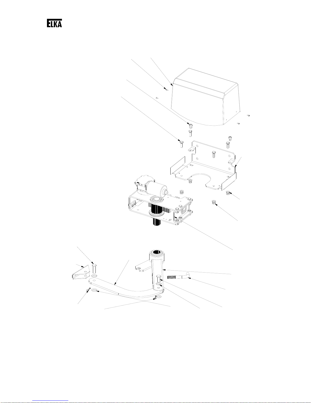
6 Configuration
Drawing 2

Function description
12
No Quantity Name or Part
1 1 Hood
2 4 Sheet metal screw ST3,5 x 9,5
3 2 Cylinder head bolt DIN 912 – M8 x 12
4 4 Hexagon head screw DIN 933 – M8 x 25
5 1 Fixing bracket
6 4 Washer DIN 125 – A 8,4
7 4 Hexagon nut DIN 985 – M8
8 1 Operator unit
9 1 Driving lever, long version
10 1 Emergency release lever
11 1 Bolt 12 x 32
12 4 Washer DIN 125 – A 13
13 2 Eyebolt DIN 94 – 3,2 x 18
14 1 Gate support
15 1 Bolt 12 x 40
16 1 Push rod, long version
Table 2
7 Function description
The bending and straightening of the articulated arm effects the opening and closing of the gate. The
end positions are programmed in the learning sequence. During operation the gate opener shuts down
at these end positions and the mandatory mechanical end stops.
For gate wings of 3,000mm length and longer we stipulate the use of an electromagnetic bolt / motor
lock for additional blocking.
The controller MO 36 offers the possibility to activate the gate wings by radio remote control.
The controller is able to observe the max. permitted force which was set before in the learning
sequence. If during the gate movement more force is needed, the gate openers reverse. Additionally
several different safety features, e.g. photoelectric barriers and safety contact profiles, can be
connected. The safety contact profile detection (8,2kOhm) for both directions of motion is integrated in
the controller.
Mechanical installation
13
8 Mechanical installation
8.1 Notes of safety
ATTENTION!
The controller and/or motor need to be disconnected from the gate while electric
welding is performed!
Welding can damage the controller and the motor.
Remove the controller and the gate opener from the gate/gatepost when welding work is
planned there.
REMARK!
Make sure the gate wing / wings are smooth-running and that the rotation axes are
vertical. Check if enough room for the gate opener remains, when the gate is in the end
positions.
REMARK!
Remove any interlocking system (plunger blocks etc.) or make it inoperable before the
installation of the gate.
REMARK!
All cables of the gate opener have to be laid in (protective) empty conduit according to the
application.
8.2 Required tools
Drill machine
Drill bit (stone) 12mm
Drill bit (metal) 6.8mm (8.5mm for clearance hole)
Die M8
Water level
Allen key 6mm
Flat-headed screwdriver 3mm
Crosstip screwdriver PH1
Combination wrench SW 10, SW 13, SW 17, SW 19
Measuring tape / Folding meter
8.3 Protective equipment
Safety goggles
Welding goggles
Work gloves
Mechanical installation
14
8.4 Scobe of delivery
The scope of delivery can vary depending on the model and accessories. Please check the scope of
delivery before installation.
Openers for 1 wing Openers for 2 wings
Opener unit 1x 2x
Hood 1x 2x
Controller MO 36 1x 1x
Operating manual 1x 1x
Articulated arm 1x 2x
Emergency release key 1x 2x
Push rod 1x 2x
Gate support 1x 2x
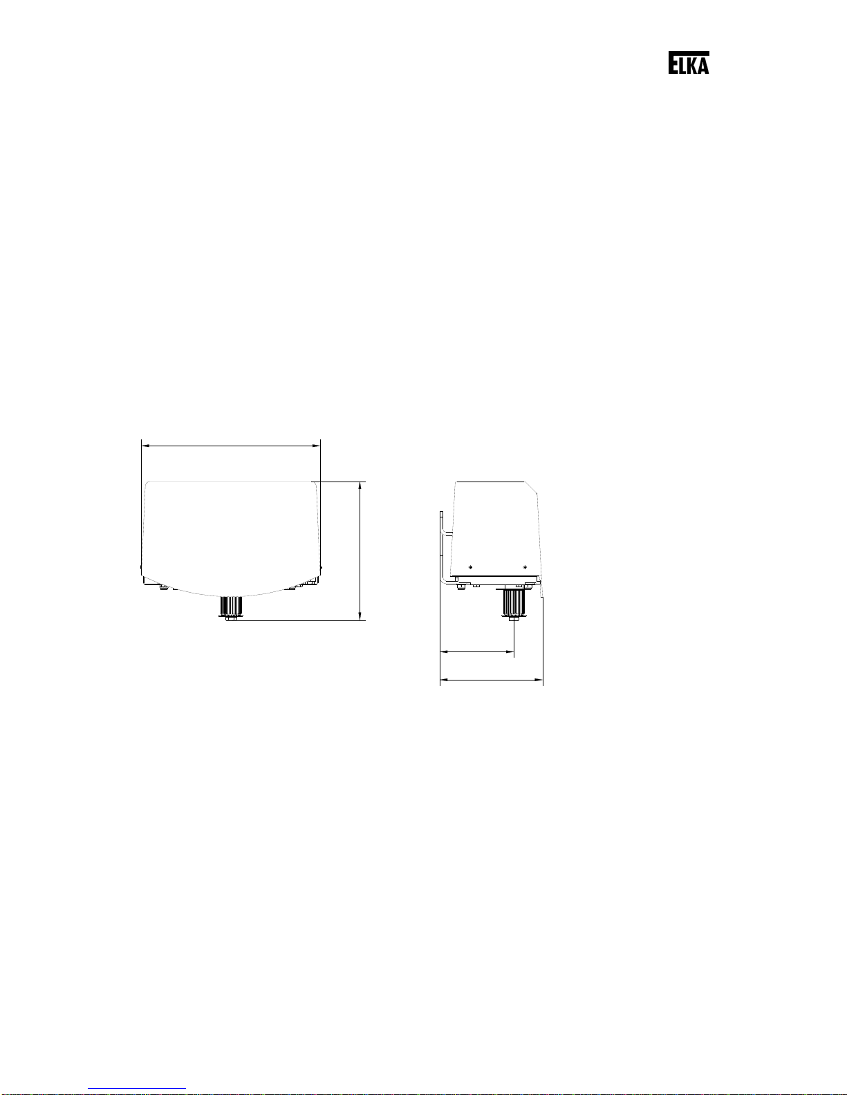
8.5 Dimensions
295
169
229
122
Drawing 3
Drawing 3 shows the housing dimensions of the gate opener.

Mechanical installation
15
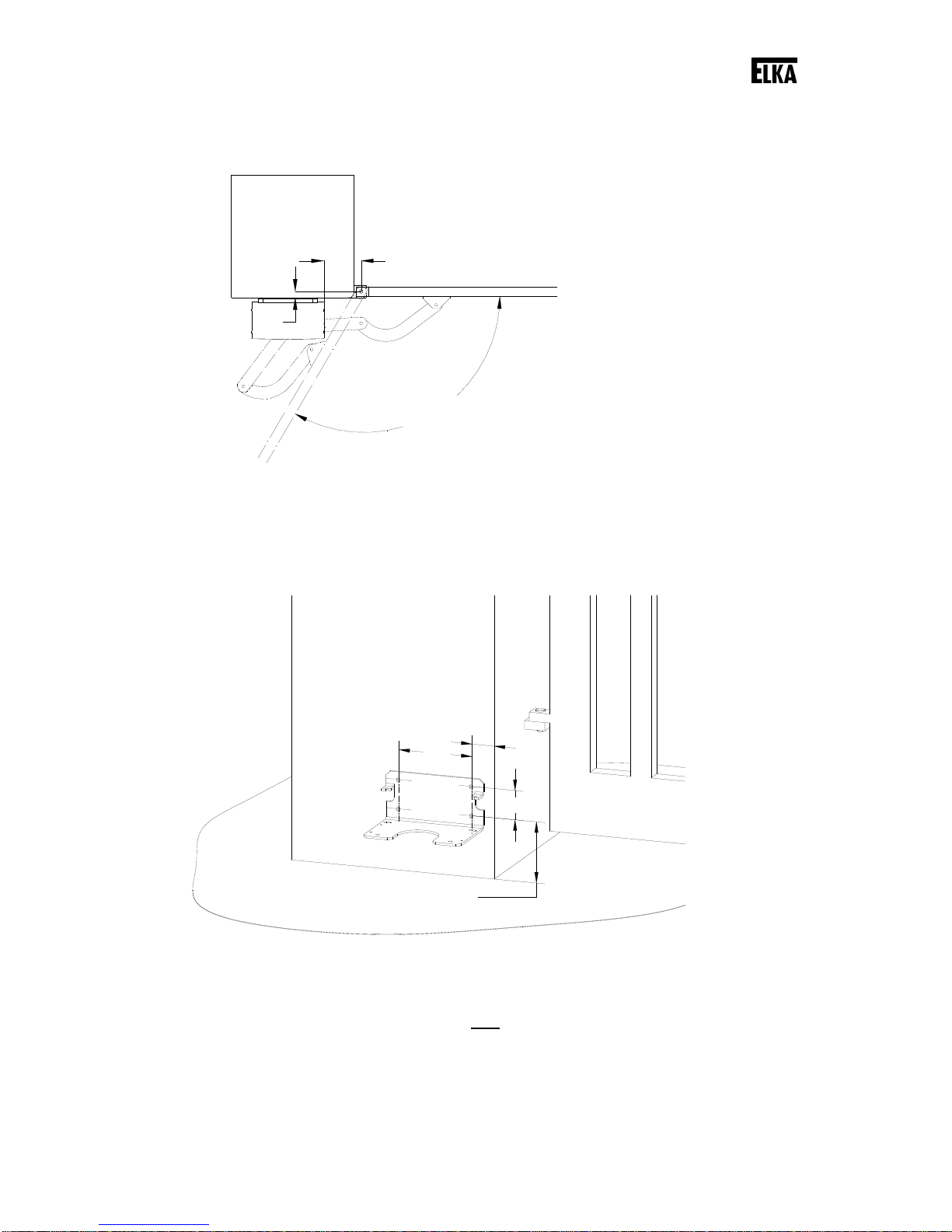
8.6 Installation dimensions
A
B
E
C
D
170°-175°
1035
122
164
Drawing 4
REMARK!
All measurements are stated in millimetre. The gate openers are for left and right gate
wings (without alteration).
Permitted installation dimensions
A 35 to 450mm
B max. 45mm if A ≥400mm
B up to 80mm if A ≤400mm
C C = 0mm if 0° ≤D ≤90°
C C up to max. 120mm if 90° ≤D ≤120°
E up to max. 685mm (depending on the gate)
Table 3
Definitions:
A, B The distances “A” and “B” are related to the pivot point of the gate.
C Only when the opening angle exceeds 90°, the measurement “C” changes from
0mm up to 100mm (depending on the gate).
D Opening angle
E Required space for the articulated arm (position gate OPEN)
Mechanical installation
16
8.7 Max. opening angle
120°
153
25
Drawing 5
Drawing 5 shows the installation dimensions for the max. opening angle.
8.8 Installation at the gatepost
min. 55
180
min. 150
70
Drawing 6
Move the gate into position CLOSED.
Connect the mounting plate at the gate post using four connection bolts (10mm diameter).
In case the gate post is made of bricks we recommend the use of special anchor bolts.

Mechanical installation
17
min. 150
58
Drawing 7
Check if with the desired installation height of the mounting plate a safe and stable installation of the
gate support at the gate leaf/ gate frame is possible. If necessary correct the installation height
upwards/downwards (see also Drawing 12).
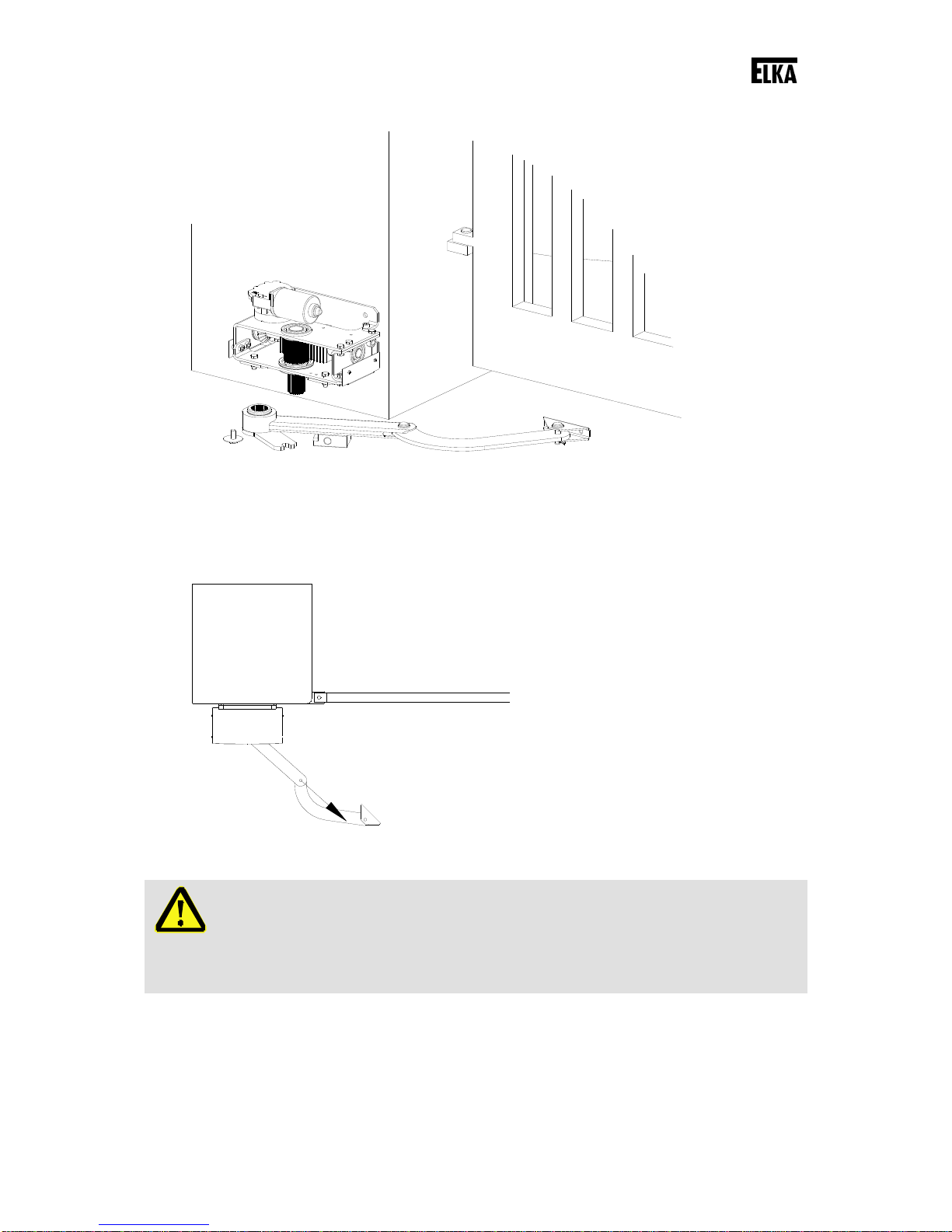
Drawing 8
First fasten the mounting plate to the gatepost and then the operator unit onto the mounting plate.
Mechanical installation
18
Drawing 9
Mount the articulated arm on the drive shaft of the operator unit. The push rod has to point towards the
gate opening (approx.45° - see Drawing 10).
Drawing 10
WARNING!
Risk of crushing on protruding parts!
Body parts can be jammed between the upper and lower halves of the articulated arm.
Do not reach into the shear zone between the upper and lower halves of the articulated
arm.

Mechanical installation
19
61°
61°
2
43
1
Drawing 11
Disengage the articulated arm using the emergency release key (see Drawing 11). To do so move the
emergency release key from position 1 to position 2. Then turn the articulated arm into the direction of
position 3, the driving lever divides itself into one upper and one lower half.
Drawing 12
Close the gate completely. Turn the articulated arm towards the gate. Align the articulated arm
horizontally.
The distance between the pivot point of the drive shaft and the pivot point of the gate support has to
be 1035mm (see also page 15, Drawing 4).
Mechanical installation
20
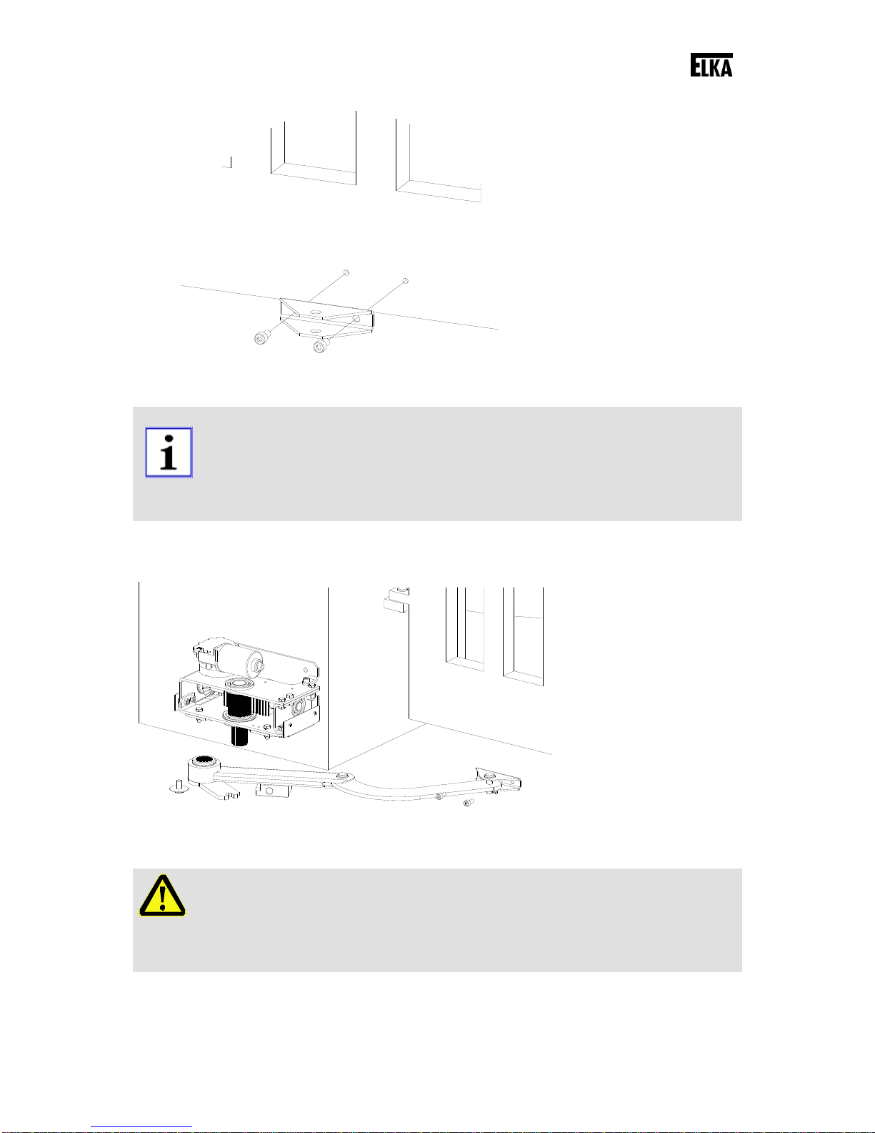
Drawing 13
REMARK!
For fastening drill and cut two M8-threads into the gate beam. Fasten the gate support
with two screws M8 x 16 (e.g. cylinder-head bolts DIN 912).
Should the material thickness not be sufficient, drill clearance holes through the gate
beam and use cylinder-head bolts in a suitable length and self-locking hexagon nuts on
the opposite gate side.
Fasten the gate support at the determined position. Then fix the articulated arm at the gate support.
Drawing 14
WARNING!
Risk of crushing!
In case the articulated arm is mounted incorrectly, the upper and lower halves can form a
shear point or crushing point.
Therefore ensure a correct installation of the articulated arm.
This manual suits for next models
7
Table of contents
Other Elka Gate Opener manuals


