Gatekeeper YG-5602/1U/E User manual

YG‐5602/1U/ESWINGINGGATE
OPENER
OWNER’SMANUAL

1
©2011
GatekeeperLtd.
P.O.Box752
Lacey’sSpring,AL35754
http://www.gatekeeperltd.com

2
Table of Contents
1. Safety Precautions........................................................4
2. Features........................................................................5
3. Specifications...............................................................5
4. Necessary Tools and Equipment..................................6
5. Site Preparation............................................................6
5a. Standard Power..................................................................6
5b. Solar Power........................................................................6
5c. Equipment Check...............................................................7
5d. Parts for Gate Arm Installation..........................................8
5e. Actuator Specifications and Measurements.......................9
6. Gate Arm (Actuator) Installation...............................10
6a. Determine Gate Open Direction ......................................11
6b. Pull to Open Inward.........................................................12
6c. Push to Open Outward.....................................................13
7. Stopper and Latch Installation...................................14
8. Electrical Installation.................................................16
8.1 - Connecting the AC Power.............................................16
8.2 - Wiring the Battery (see Fig.7b).....................................17
8.3 - Wiring the Actuators.....................................................17
8.4 - First Time Activation Test.............................................18
9. Using the RF Remote Control....................................18
10. External Interfaces...................................................20
10.1 - Keypad/ Button Switch ...............................................20
10.2 - Loop detector...............................................................20
10.3 - Safe guard (Infrared device or Photocell)....................21
11. Advanced Control Wiring........................................22
11.1 -Visual Guide for Wiring................................................24
13. Auto-close function..................................................26
14. Additional Features..................................................26
15. Operation Notes on the Gate Opener System..........27
16. Maintenance & Troubleshooting .............................28
17. Gatekeeper Ltd. Limited Warranty..........................30

3
THIS PAGE INTENTIONALLY LEFT BLANK

4
1.SafetyPrecautions
InstallingtheYG‐5602/1GateOpenerrequiresinstallationofstandard
110Vor230Velectricalwiring.Thisworkshouldonlybeperformedbya
trainedtechnician.Mis‐wiringcouldcausepersonalinjuryorDEATH.To
preventtheriskofelectrocution,besuretoturnoffallpowertotheYG‐
5602/1untilinstallationiscomplete.
Pleasekeephands,fingersandlooseclothingawayfrommovingpartsas
theymaybedraggedintomovingparts.
Thegatemaymoveatanytime.Ensureallpersonsareclearofthegatewhen
itismovingtoavoidtheriskofinjury.Donottouchthegatewhileitisin
operation.Donotattempttogothroughthegatewhileitisstillinmotion.
Thisopenerisintendedforvehicularuseonly.
Donotallowchildrenorpetsnearyourgate.Keeptheremotecontrolsaway
fromchildren.Placecontrolswheretheycannotbeaccessedbyreaching
throughthegate.
Toavoidelectricshock,unplugunitbeforeopeningcase.
Makesurethebatteryinsidetheopenerischargedfullybeforeusing.
Beforeinstallation,theclutchshouldbeunlocked.
Theauto‐reversefunctionmustbecheckedduringinstallationtoensurethat
thegatecanauto‐reverseintheeventofobstruction,anditshouldbe
inspectedregularly.
Theautomaticgateopenermustbegrounded.
Installthegateopenerontheinsideoftheproperty;DONOTinstallitonthe
outsideofthepropertywherethepublichasaccesstoit!
Additionalsafetyequipmentsuchasphotoelectricsensors,safetyedges,
rollerguardsandwarningsignsmustbeinstalledtopreventinjury.
Intheeventofpowerfailure,anemergencyreleasekeyallowsyoutooperate
thegatemanually.
Pleaseeraseandresetthecodeafterinstallingtheopener.
Thegateopenershouldbeinstalledbyaqualifiedtechnician;otherwise,
seriouspersonalinjuryorpropertydamagemayoccur.
Forservice,callanexperiencedtechnician.Donotinanywaymodifythecomponentsof
theautomatedsystem;otherwiseseriouspersonalinjuryorpropertydamagemayoccur.
Wedonotacceptresponsibilityfordamageorinjuryresultingfromtheinstallationofthis
opener.

5
2.Features
ClassI:Avehiculargateopener(orsystem)intendedsolelyforuseinasinglefamilyhome,
oranassociatedgarageorparkingarea.
ADDITIONAL FEATURES
Supportssingleordualgateoperation.
Adjustableautoreversefunctionforsafetypurposes.
Built‐inbatterybackupintheeventofpowerloss.
Auto‐closefeaturewith3waittimes:12/25/50selectablebydipswitch.
Batterylow‐voltagedetectiontoavoidbatterydamage.
Automaticslowdownfeaturetodecreasenoisyclosing.
Keypad/singlebuttoninterface.
Infraredsafetybeaminterface.
Supportsupto15RFremotes,2included.
Userprogrammableandusererasableremotecodes.
RFhoppingcodetechnologypreventsthievesfromguessingyourremotecode.
Manualkeyreleasedesignforemergencypurposes.
SupportsKeypadinterfaceandMagneticLoopDetectorssimultaneously.
3.Specifications
PowerSupplyUModel110VAC(60Hz)
EModel230VAC(50Hz)
BackupBattery:12VDC/4AH
MaximumNumberofRemoteControls15(2Included)
MaximumGateWeight300KG/661lbs
MaximumGateWidth3.6meters/12feetperleaf
DutyCycle50%
WorkingTemperatureRange:‐20°C‐~55°C,‐4°F–~131°F
PowerConsumption:150W(Max)
5W(Standby)
PowerSupplyoftheMotor12VDC/8A,96W(MAX)
PowerSupplyoftheLamp:12VDC,21W(MAX)
PowerSupplyoftheElectricLock:12VDC,60W(Max)
PowerSupplyoftheReceiver:12VDC,2W(Max)
PowerSupplyoftheAccessories:12VDC,3W(Max)
Over‐current‐protection:3.5A~7.5A
PauseTime:Programmable,0sec~50sec
2ndLeafClosingDelay:Programmable,0sec~8sec

6
DimensionsandWeight:300x245x90mm,4.6kgs
11.8”x9.65”x3.5”,10.1lbs
4.NecessaryToolsandEquipment
ThefollowingtoolsmaybenecessarytoinstalltheYG‐5602/1Gateopener.
StandardandPhilipsscrewdrivers
Electricdrill
Wirecutters
Wirestripper
Socketset
Welder
5.SitePreparation
Beforeyoubegintheopenerinstallation,checkthefollowing.
1. Thegateshouldbemountedandmovingfreelywithlittleresistancein
movement.
2. Thegateandpostmustbesuitableforbeingautomated.Checkthatthe
structureissufficientlystrongandrigid,andthatitsdimensionsandweights
conformtothoselistedinthespecificationstableofthisdocument.(page5)
3. Makesurethatthegateisplumbandlevel.
4. Thefencepostsmustbemountedinconcrete.
5a.StandardPower
TheYG‐5602isnormallypoweredbyU/Estandardpower(Umodel110V/60HzAC;Emodel
240V/50HzACpower)Ifyouhavenotalreadydoneso,wireawaterproofoutletnearthegate
followingpropersafetystandardsforyourarea.Ifyouarenotexperiencedwiththistypeof
wiringorifyourarearequiresit,hireaprofessionalelectriciantoperformthisaswellas
wireintheYG‐5602intheelectricalsection.
TheYG‐5602requiresatleasta15Aservice.Makesureyourelectriciantakesintoaccountthe
voltagedropinvolvedinrunningmanyfeetofwiretoyourinstallationlocation.Ifan
insufficientgaugeofwireisused,therewillbeinsufficientpoweratthesitetooperatethe
opener.
5b.SolarPower
Ifyouplantousesolarpanelstopoweryourgate,verifythatyouhavesufficientsolarpower
tochargethebatteryandprovidepowerforthenumberofopeningsandclosingsyouplanto
need.Differentareasoftheplanetreceivevaryingamountsofsunlight,andthatamount
variesonthetimeoftheyear.Makesureyouaccountforallthisinanysolarinstallation.
Ifinsufficientpowerisavailable,theopenerbatterycanbepermanentlydamagedandthis
isnotcoveredunderthewarranty.

7
5c.EquipmentCheck
1. SwingingGateActuator
2. “T”MountingBracket
3. Flashinglight
4. Throughbeamtypeinfra‐redphotosensor
5. ElectricLatchwithKeylock
6. Mountingbracket
7. Antenna
8. Controlbox
9. CotterPin
10. ClevisPin
11. Keysandmanualkey‐lock
12. Remotekey
*Notshowninpicture
1. StopBlock
2. “L”Mountingbracket
3. BarMountingbracket
4. Assortedboltsandnuts

8
5d.PartsforGateArmInstallation
Youneedthefollowingpartstoconnectanactuatortoyourgate.
NoDescriptionQuantity
Single Dual
1Actuator12
2NestPin12
3FastenerScrew12
4“L”MountingBracket24
5BarMountingBracket12
6NutforBolt24
7Bolt24
8ReleaseKey12
9Bolt612
10CotterPin12
11“T”MountingBracket12
12FrontClevisPin12

9
5e.ActuatorSpecificationsandMeasurements
1. ActuatorMaximumDirectForce:1400N,315lbs
2. ActuatorMaximumPowerConsumption:12Vat6A=72W
3. DutyCycle:50%
30mm,1.2"
“T” Mounting Bracket
150mm, 5.9"
20mm,
.78" 20mm,
.78" 20mm,
.78" 20mm,
.78"
8mm,.31"
15mm,.59"
A
30mm,1.2"
“L”MountingBracket
Figure1.
10
6.GateArm(Actuator)Installation
Beforeproceedingtotheinstallation,makesureyoureadthroughthefollowing.
GateSizeandWeightLimitations
TheYG‐5602/1SwingGateOpenerwillhandlegatesweighingupto300Kg
(661lb)andupto3.6m(12ft)perleafiftheproperinstallationprocedures
havebeenfollowed.TheYG‐5602gateoperatoroperatesbyforcingaworm
geartoextendinsideeachactuatorpushingorpullingthegateopen.
Gatepreparation
Besurethegateisproperlyinstalledandswingssmoothlybeforeinstalling
theYG‐5602swinginggateopener.Thegatemustbeplumb,level,andmove
freely.Moredetailedinstructionsonpage6(Sec.5.SitePreparation)
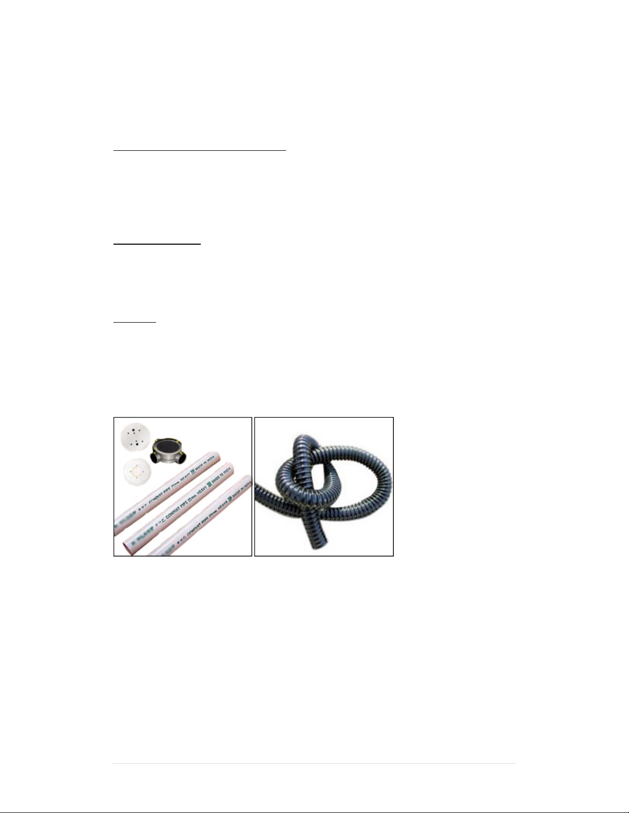
Conduit
Inordertoprotectthewires,usePVCconduitforwires.Itmaybenecessary
topresettheconduitintotheconcretewhenitispoured.Wireswithinthe
conduitshallbelocatedorprotectedsothatnodamagecanresultfrom
contactwithanyroughorsharppart.Moredetailedinstructionsonpage6
(Sec.5aStandardPower&5bSolarPower)
PVCConduitsare
usuallypipes,butare
alsoavailableas
flexibletubes
Oncethegateismountedadequately,andelectricalpowerisavailable,you
arereadytoproceedwiththeYG‐5602installation.
11
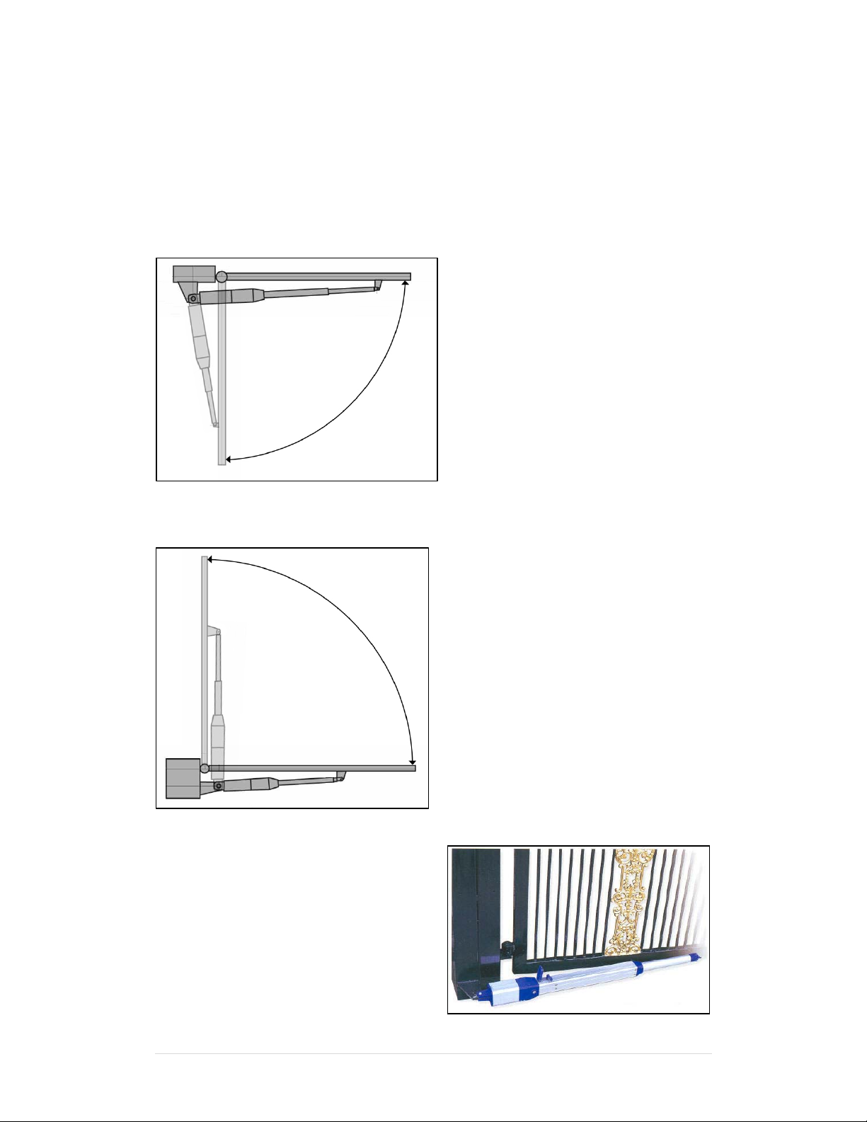
6a.DetermineGateOpenDirection
Beginwithbothopenersunlocked.Nextidentifyifthiswillbea“pushtoopen”ora“pullto
open”installation.Ineitherconfiguration,thegateismountedononefaceofthemounting
post,andtheopenerismountedontheface90degreesfromit.Belowareschematicsofboth
“pushtoopen”and“pulltoopen”configurations.
A.PULLTOOPENINWARD
Usethissetuptomakeyourgate
openinward,towardyourproperty.
Figure2.
B.PUSHTOOPENOUTWARD
Usethissetuptomakeyourgate
openoutward,awayfromyour
property
Figure3.
AproperlyinstalledOpenInwardactuator

12
6b.PulltoOpenInward
Mounttheactuatorsontheincludedbracketsaccordingtothefigurebelow.
Thegateismountedononefaceofthemountingpost,andtheopeneris
mountedontheface90degreesfromit.Theactuatormechanismshould
alwaysbeinsidethepropertysothatitcannotbetamperedwithfromthe
outside.Initiallymounttheactuatorsonthegatesothatthegateisopen.
Figure4.
Opening
Angle
AcmAinchBcmBinchCcmCinchDcmDinch
9017.56.8814.55.7117.846.386.52.56
110187.089.53.74118.346.576.52.56
Theinstallationshouldmeetthespecificationsshowninthefigure.Failuretodosomay
causeopeningandclosingproblems.

13
6c.PushtoOpenOutward
Mounttheactuatorsontheincludedbracketsaccordingtothefigurebelow.
Thegateismountedononefaceofthemountingpost,andtheopeneris
mountedontheface90degreesfromit.Theactuatormechanismshould
alwaysbeinsidethepropertysothatitcannotbetamperedwithfromthe
outside.Initiallymounttheactuatorsonthegatesothatthegateisopen.
Figure5.
Opening
Angle
AcmAinchBcmBinchCcmCinchDcmDinch
908.53.34135.129738.126.52.56
11012.54.92114.3385.933.826.52.56
Theinstallationshouldmeetthespecificationsshowninthefigure.Failuretodosomay
causeopeningandclosingproblems.

14
7.StopperandLatchInstallation
WITHOUTElectricalLatch
1. InstallStopper1:stopsgateinclosedposition.
2. InstallStoppers2:stopsgateinmaximumopenedposition.
Figure6a.
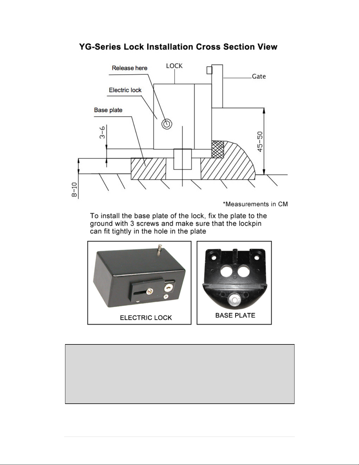
WithElectricalLatch(OPTIONAL)
3. InstalltheElectricalLatchandtheSlaveGateStoponthegateasshowninthe
diagram.
4. InstalltheLBarontheoppositegate
5. InstallStopper1:stopsgateinclosedposition.
6. InstallStoppers2:stopsgateinmaximumopenedposition.
Figure6b.
See“YG‐SeriesLockInstallationCrossSection”onthenextpage
tounderstandhowtheElectricalLatchfunctions.
15
Figure6c.
MechanicalMaintenance
Regularlyverifythatthegateswingsfreely.
Addgreasetothegateasdirectedbythemanufacturerofthegate.
Checkthatwiringandotherelectricalpartsareweather‐proof.
Keepopenercleanatalltimes.

16
8.ElectricalInstallation
CONTROL BOX DIAGRAM
8.1‐ConnectingtheACPower
Thecontrolboxshouldbeequippedwithasingle‐phasebreaker(15A).Makesurethatthe
powerisOFFbeforemakinganyelectricalconnections.Removethecoverofthecontrolbox,
performthewiringandreplacethecoveragain.
WireyourAClineintotheACINterminalatthetopofthecontrolboxnearthetransformer.
Wiretheground(usuallygreen)totheterminalontheleft.
Wirethehot(usuallyblack)wiretothemiddleterminal.
Wiretheneutral(usuallywhite)wiretotheterminalontheright.
Verifythatallelectricalconnectionsarewaterproofbyinstallingelectricaloutletsintoexterior
gradeboxeswithwaterproofcovers.Makesurethatwheneveranelectricalconnecterenters
orexitsaboxitissealed.Ifusingsolar,verifythatallconnectionsarewaterproof.Please
Notethesystemcannotexecutethelearningmode(remotecontrol)bybatterypoweronly.
Onceyourbreakerisactivated,theLEDshouldlight.

17
8.2‐WiringtheBattery(seeFig.7b)
Insidethecontrolbox,connecttheredbatteryleadto‘BAT+’terminalofcontrol
board,andblackbatteryleadto‘BAT‐’.UseterminalJ8forthebattery.
Battery
BLACK WIRE TO POSITIVE-
RED WIRE TO POSITIVE+
Figure7b.
Definitionofflashinglightcodes:
QuickflashinglightSystemsoperationisatslowdownspeedorthesystemisin
learningmode/kickback/extra‐pushphase.
NormalflashinglightSystemisoperatingatthefullspeed.
SlowflashinglightGateiswaitingforautocloseexecution.
Lampfixedlight7sec
withoutgatemovement
Gateisinawaitingmodesincethephotocellhasbeencovered
byobstacleduringthegateclosingoropening.
8.3‐WiringtheActuators
ConnectthewiresfromthemasterornumberonegateactuatortotheMM1
terminals1&2onthecontrolboard.Connectthewiresfromtheslaveornumber2
gateactuatorintotheSM2terminals3&4onthecontrolboard.Ifusingasinglegate
only,thenconnectthesingleactuatortoMM1only.
Makesurethattheactuatorsaremountedsothatwhenactivatedtheywillclose,
i.e.mounttheactuatorssothatthegateisopen(actuatorsareretracted).

18
8.4‐FirstTimeActivationTest
TwoGateOperation
Pressthebuttonforchannel2ontheremotecontrol(blackbutton)andthe
programmingsystemswillenterinto“systemself–learningmode”.Thelampwill
startquickflashingandthemotors(onebyone)willstartmovingthroughthe
followingsteps:
SlaveGatewillClose(actuatorextending)MasterGatewillClose(actuator
extending)MasterGatewillOpen(actuatorretracting)SlaveGatewillOpen
(actuatorretracting)SlaveGatewillClose(actuatorextending)MasterGate
WillClose(actuatorextending).
SingleGateOperation
Forthesinglegate,whenthesystemreceivesasignalfromchannel2,thelampwill
startquickflashingbutthesystemwillexecutelearningmotionafter75sec.The
learningmodewillexecuteasthefollowingstep:
MasterGateClose(actuatorextending)MasterGatewillOpen(actuator
retracting)MasterGateWillClose(actuatorextending)
Verifyopendirection
Ifthegatedoesnotmoveinthedesireddirection,thenyouwillneedtoreversethe
motoroperatingdirection.Nomatterwhichmethodofinstallationisused,pullto
openorpushtoopen,thefirstoperationshouldbedefinedasgateclosingphase
duringtheprocedureforlearning.Ifthesystemexecutestheoppositemotionduring
thelearningmode,pleaseswapthewiresofthemotortothecorrectpolarity.
DetermineifAdjustmentisRequired
Duringthe“systemlearningmode”,therearetwosituationsthatneedtobeadjusted
forusingtheVR1(overcurrentsensitivity/obstructionsensor)
Ifoneleafstopsbeforearrivingattheendoftravel.
Ifoneleafstopsatendoftravelbuttheotherleafisnotmovingandthelamp
isstillquickflashing.
AfteradjustingtheVR1,repeattheself–learningsystemfromthebeginning.
Important
Duringthe“SystemSelfLearningProcess”,ifanycommandinterruptstheleafʹs
travel(TransmitterorPush‐buttonorotherabnormalstop),.the“SystemSelf
LearningProcess”willnotbesuccessfulandthe“SystemSelfLearningProcess”
mustberepeatedagainfromthebeginning.
Incaseoftheabsenceofapowersupply,thestoredlearningmemorywillbe
lostandthesystemsshouldexecutethe“SystemSelfLearningProcess”again.

19
9.UsingtheRFRemoteControl
Fig.8
WARNING:Notifytheusersthatthegateisnevertobeoperatedunlessitisinfullview.
Howtoaddanadditionalremotecontrol
PleasepressbuttonSW2,theL4(LEDforcodelearning)willbeturnedonandthereceiver
modulewillbechangedtothe“RFRemoteLearningMode”for30seconds.Duringthe“RF
RemoteLearningMode”period,pressthemainbuttonone(blackoneontheleft)ofthe
transmitter,itwillthenbememorized(upto15differenttransmitterscanbememorized).
AftertheLEDlightisturnedoff,thereceivermodulewillgobacktothe“normalmode”and
thesystemcanbeoperatednormally.
Upto15remotecontrolsmaybeused.AdditionalRFRemotecontrolscanbeobtained
throughyourdealer.Tofindadealergotowww.gatekeeperltd.com/dealers
Howtoeraseremotecontrols
Toeraseexistingremotecontrols,thememorycanbeclearedcompletelyiftheSW2(code
learning)ispressedcontinuouslyfor10seconds.
Table of contents
Other Gatekeeper Gate Opener manuals


