Topens LC1100 User manual

Sliding Gate Opener
User’s Manual
Model:
TOPENS Website
www.topens.com
Email: supp[email protected]m
VER 23b
C030688
★Please read and follow all warnings, precautions and instructions before
installation and use.
★Periodic checks of the opener are required to ensure safe operation.
★Save this manual.
LC1100

CONTACT US:
Visit: www.topens.com
Please record the product model, your email address etc.
in the spaces provided below. Refer to this list when contacting TOPENS
for technical service or assistance with your automatic gate opener.
Where did you purchase? (Amazon.com; Amazon.ca: Amazon.co.uk, Amazon.de; Other, Please
Specify)
Order#
Product Model
Purchase Date
Full Name
Phone#
Email Address (VERY
IMPORTANT)
Street Address, Apartment /Unit, City, State /Province, Zip Code
Country/Region
Approximate Gate Weight
(pounds; kg: Other. Please
Specify)
Approximate Gate Length
(feet; meter; Other. Please
Specify)
Did you purchase any
accessories? (Please list
below)
Issue Details
Email Us: support@topens.com
Call: +1 (888) 750 9899 (Toll Free USA & Canada)

Table of Contents
Check Your Gate before Installation ................................................................................................................1
IMPORTANT SAFETY INSTRUCTIONS .........................................................................................................1
Parts List...........................................................................................................................................................2
Accessories Parts (Included in some models, refers to the actual package) .......................................................2
Optional Accessories Parts List (Available at TOPENS Store).............................................................................2
Replacement Parts ...............................................................................................................................................3
Tools Needed ................................................................................................................................................... 3
Technical Specifications & Features ................................................................................................................3
Opener Installation ........................................................................................................................................... 4
Installation Overview.............................................................................................................................................4
Foot Pedal Release ..............................................................................................................................................4
Mounting Opener to Concrete Pad .......................................................................................................................5
Correct Chain Installation......................................................................................................................................5
Types of Installations ............................................................................................................................................6
Adjust the Limit Switches ......................................................................................................................................7
Connection of Power Supply............................................................................................................................8
Connection between Master and Slave Gate Opener .....................................................................................9
Connection of the Control Board...................................................................................................................... 9
How to Program or Erase the Remote...........................................................................................................12
Setting of the Control Board........................................................................................................................... 12
1. DIP Switches...................................................................................................................................................13
2. Potentiometers................................................................................................................................................14
How to Use the Remote to Operate Your Gate Opener ................................................................................ 15
Wireless Keypad Programming......................................................................................................................15
Trouble Shooting ............................................................................................................................................16

1
Thank you for purchasing our gate opener. We are sure that the products will be greatly satisfying as soon
as you start to use it.
The product is supplied with a user’s manual which encloses installation and safety precautions. These
should be read carefully before installation and operation as they provide important information about
safety, installation, operation and maintenance. This product complies with the recognized technical
standards and safety regulations.
Check Your Gate before Installation
IMPORTANT SAFETY INSTRUCTIONS
WARNING – To reduce the risk of severe injury or death:
1. READ AND FOLLOW ALL INSTRUCTIONS.
2. Installation should be performed by a professional installer.
3. Should electricity be required, use a certified electrician only.
4. Never let children operate or play with gate controls. Keep the remote control away from children.
5. Always keep people and objects away from the gate. NO ONE SHOULD CROSS THE PATH OF THE
MOVING GATE.
6. Do not operate the gate unless area around gate is in full view.
7. Always disconnect the power source when making adjustments or repairs to any part of the opener.
8. Use the manual release only when the gate is not moving.
9. The entrance is for vehicles only. Pedestrians must use separate entrance.
10. SAVE THESE INSTRUCTIONS.

2
Parts List
Accessories Parts (Included in some models, refers to the actual package)
Optional Accessories Parts List (Available at TOPENS Store)
M12 Remote Control
ERM12 External
Receiver
TC196 Tuya WIFI
remote control
TC188 Universal Wireless
and Wired Keypad
TKP3 Wireless Keypad
TC175P Wired
Keypad
TEW3 Vehicle Sensor
Exit Wand
HLR01 HomeLink Remote
Control Kit
TC173 Wireless Push
Button
TC147 Wall Push
Button
TC148 Waterproof Wall
Push Button
TRF3 Reflection Photocell
Sensor
TC102 Photo Eye Beam
Sensor
JD110VY AC Warning
Light

3
Replacement Parts
ACPYMJ9A
Control Board (120V)
MS8013A1BBC1
Limit switch
Tools Needed
·Power Drill ·Portable Electric Welder ·Tape Measure ·Level ·Hammer ·Wire Strippers
·Screwdriver ·Hex Key Wrench ·Open End Wrenches or Adjustable Wrenches
·An extra person should be needed
Technical Specifications & Features
Specifications
Input:
110V~120V/60Hz
Motor:
3/4 HP(550W), 120VAC
Current:
8.5A
Gate travel speed:
24 cm/s(9.4 in/s)
Max. Gate travel:
13.7 m(45 feet)
Max. Gate weight:
1300 kg(2800 lbs)
Duty cycle:
100%
Power failure release:
Exclusive foot pedal release
Ambient temperature:
-20℃~ +50℃ (0°F to 120°F)
Protection class:
IP44
Features:
·Emergency Exclusive foot pedal release in case of power failure
·Easy to install, and minimum maintenance requirement
·Midway mode
·Quick selection for gate open/close direction
·Get the desired chain tension by adjusting the chain bolts
·Reliable rolling code technology for remote control
·Stop in case of obstruction during gate opening
WARNING: Changes or modifications not expressly specified by this user manual, TOPENS could void
the warranty of this equipment.

4
·Reverse in case of obstruction during gate closing
·Built in adjustable auto-close (0-99 seconds)
·Built in max. Motor Running Time (MRT) for multiple safety protection (90 seconds)
·Reliable microswitch limit for easy adjustment
·Can be equipped with wide range accessories
Opener Installation
Prior to beginning the installation of sliding Gate opener, we suggest that you become familiar with
instructions and illustrations in this manual. This will help insure that your installation is performed
in an efficient and professional manner.
Installation Overview
Foot Pedal Release

5
EMERGENCY RELEASE
1. Exclusive foot pedal release disengages the gate from the motor so it can be opened manually.
2. After proper use of the foot pedal, be sure to lightly kick the pedal towards the right side to spring the
pedal up and re-engage your gate.
WARNING – We do not recommend use of the foot pedal on installations with steep inclines.
Always make sure the gate is secured when using the foot pedal to avoid sudden movements from
the gate.
Mounting Opener to Concrete
Pad
Be sure that the opener is installed in a level
and paralleled position and is properly
secured. Improper installation could result in
property damage, severe injury, and/or
death.
Concrete Pad dimensions are Min.
490*475*400mm
Correct Chain Installation

6
Types of Installations
................................................................................................................................................................................................

7
Adjust the Limit Switches
★Turn power off before attempting adjustment ★
To adjust the limit switches, depress spring loaded bracket and spin each Adjustment Nut to the required
position.

8
Connection of Power Supply
WARNING: NEVER connect the gate opener to the power supply before all the installations
have been done.
CAUTION: The gate opener is classified to permanent connected appliances, CONNECTED
the power supply to the ELECTRIC GRID directly. A 10A breaker with GFCI protection (Not included)
must be added in wire connection for single gate opener. A 20A breaker with GFCI protection must
be added in wire connection for dual gate opener.
Connect the power supply to the gate opener refers to the following illustration.
NOTE:
1. The wire size should be at least 14AWG which is intended
to connect the power supply when it’s single gate opener.
The wire size should be at least 10AWG which is intended to
connect the power supply when it’s dual gate opener.
2. Run the wires in conduit to the control box to prevent
damage to the wires from lawn mowers, weed eaters and
grazing animals.

9
Connection between Master and Slave Gate Opener
In the dual gate opener system, the slave gate opener is controlled by the master gate opener, so the slave
gate opener must be connected to the master gate opener for communication. Use a 2-core shield
twisted-pair wire (minimum size of the wire is 20AWG) to connect the two control board refers to the
following illustration.
Connection of the Control Board
Warning: Before making any electrical wire connection or/and setting the control board, make
sure that the power switch is OFF.
Warning: A photocell is included in the package. The photocell must be installed with the gate
opener for safety protection or the gate opener could not run properly.
For SINGLE GATE OPENER, the connection of the control board can be simply referred to the following
illustration.
For DUAL GATE OPENER, you should configure the master gate opener and the slave gate opener firstly.
All the accessories must be connected to the control board of the master gate opener because the
system is controlled by the master gate opener. For the slave gate opener, you just need to connect
the AC power wire and the communication wire to the master gate opener.
Following illustration is the connection of the control board:

10
1. Motor
The WHITE wire of the motor should be connected into the “5” terminal.
The RED wire of the motor should be connected into the “6” terminal.
The BLACK wire of the motor should be connected into the “7” terminal.

11
2. Limit Switches
The YELLOW wire of the limit switches should be connected into the “10” terminal.
The GREEN wire of the limit switches should be connected into the “11” terminal.
The BLUE wire of the limit switches should be connected into the “12” terminal.
3. Warning Light (Included in some models, refers to the actual package)
One wire of the warning light should be connected into the “3” terminal, another should be connected into
the “4” terminal. The rated voltage of the warning light should be the same as the power input of the gate
opener.
4. Electromagnetic Lock (Optional)
Positive input of the lock should be wired into “9” terminal and negative input of the lock should be wired
into “8” terminal.
5. Audio Alarm
The RED wire of the buzzer should be connected into the “15” terminal.
The BLACK wire of the buzzer should be connected into the “16” terminal.
6. Photocell Beam System (PBS) (Included in some models, refers to the actual package)
You should remove the jumper wire which is shorted between “PHOTOCELL” (17&18 terminal) before
attaching a photocell. Use a 2-core cable to connect the “+ ~” terminal of the photocell’s emitter to the “14”
terminal, the “- ~” terminal to the “13” terminal. Also the “+ ~” and “- ~” terminals of the photocell’s
receiver should be connected to the “14” and “13” terminals in parallel.
Use another 2-core cable to connect the “COM” terminal of the receiver to the “17” terminal, the “NC”
terminal to the “18” terminal.
7. Reflection Photocell Sensor (optional)
The “AC10-25V/DC12-30V” terminals of the reflection photocell sensor should be connected to the “14” and “13”
terminals, no matter the polarity.
The “NC” terminal should be connected to the “18” terminal.
The “COM” terminal should be connected to the “17” terminal.
NOTE: The terminal 17 and 18 on control board should be shorted if the photocell beam system
(optional) does not use. A wire jumper has been used for short to terminal 17 and 18 in factory.
Please check if this wire jumper is missing or keep the photocell in alignment when the gate can
open but fails to close.
8. External Receiver (Optional)
The BROWN wire of the external receiver should be connected into the “20” terminal.
The BLACK wire of the external receiver should be connected into the “19” terminal.
The RED wire of the external receiver should be connected into the “14” terminal.
9. Push Button (Optional)
The push button should be wired to the “19” and “20” terminals. The gate operator works alternately by
pushing the button (open-stop-close-stop-open).
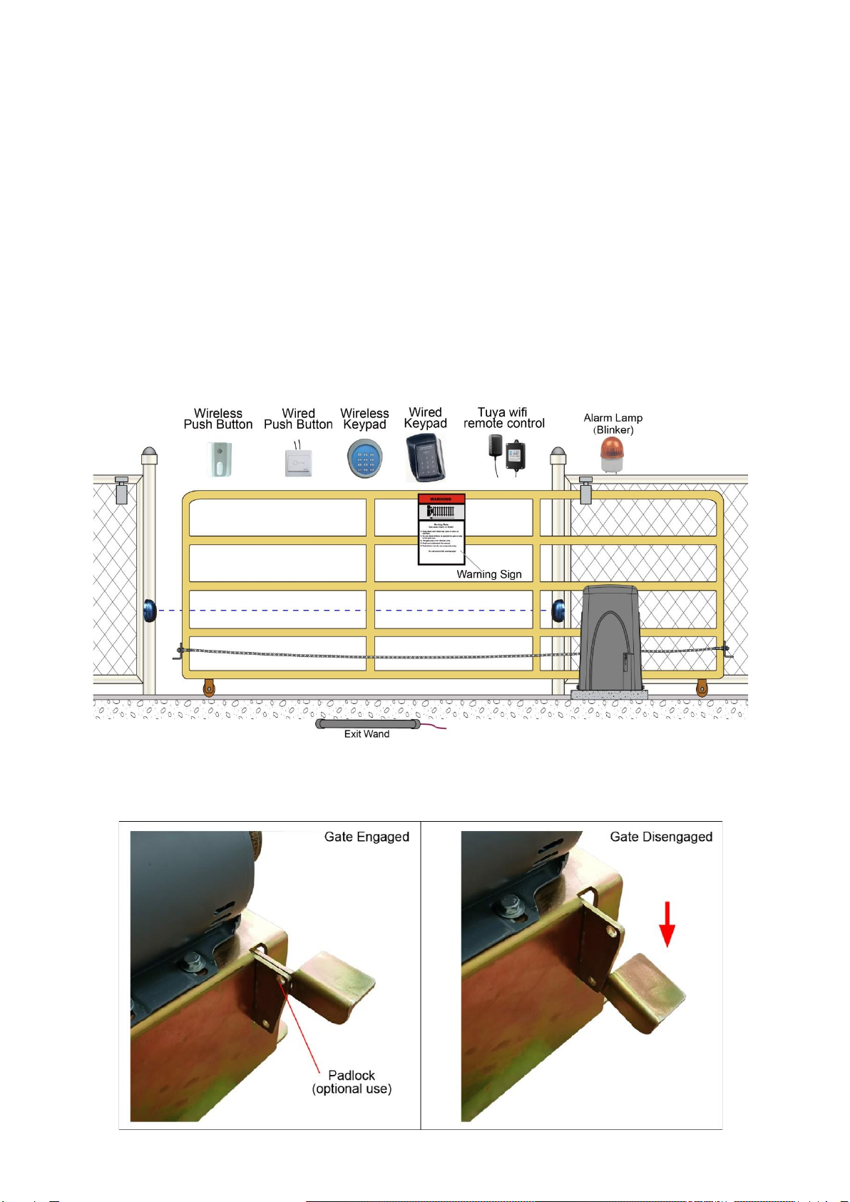
10. Exit Wand (Optional)
The RED wire of the exit wand should be connected into the “14” terminal.
The GREEN wire of the exit wand should be connected into the “13” terminal.
The BLACK wire of the exit wand should be connected into the “21” terminal.
The BLUE wire of the exit wand should be connected into the “22” terminal.
The range adjustment board should be wired between YELLOW wire and GREEN wire of the exit wand.
11. External Antenna (Optional)
If the antenna is a single core cable, it should be connected into “25” terminal directly. If the antenna have a
shielding layer, the shielding layer should be connected into “26” terminal.

12
12. HomeLink Remote Control Kit (optional)
The “1” terminal should be connected to the “19” terminal.
The “2” terminal should be connected to the “20” terminal.
The “DC+” terminal should be connected to the “14” terminal.
The “DC-” terminal should be connected to the “13” terminal.
13. Wired Keypad (12VDC) (Optional)
The RED wire of the wired keypad should be connected into the “14” terminal.
The BLACK wire of the wired keypad should be connected into the “19” terminal.
The PURPLE wire of the wired keypad should be connected into the “19” terminal.
The BLUE wire of the wired keypad should be connected into the “20” terminal.
How to Program or Erase the Remote
The remote MUST be programed to the opener BEFORE OPERATING. Please follow the steps to
program the remote.
Activate the opener only when gate is in full
view, free of obstruction and properly adjusted.
No one should enter or leave gate area while
gate is in motion. DO NOT ALLOW CHILDREN
to operate push button or remote. DO NOT
ALLOW CHILDREN TO PLAY NEAR THE GATE.
If you purchase additional remote controls, the
gate opener must be programmed to accept the
new remote code.
If you lose one of any remote control, please erase and reprogram all other remote controls to
have a new code for safety.
Program the remote
Press and release the Learn Button, the Learn LED will be ON, then press the key in the remote twice in 3
seconds, the Learn LED will flash for 3 seconds. Now the remote has been programmed successfully.
Erase all the remote codes
Press and hold the Learn Button until the Learn LED is off. Now all remote codes have been erased.
NOTE: Max. 8 remotes can be programmed for the opener. An External Receiver (optional) allows
up to 250pcs remotes to be programmed for the opener. TOPENS ERM12 Universal External
Receiver is available at TOPENS Store.
TOPENS ERM12 Universal External Receiver is also compatible with other brand swing gate
opener, sliding gate opener and garage door opener.
Setting of the Control Board
WARNING: Ensure the gate opener is Power Off when you make any adjustment of the gate
opener. Keep away from the gate during you set the gate opener system in case of the unexpected
gate moving. Carefully adjust the DIP switches to avoid the risk of machine damage and injury or
death. Always ask the help of professional technician /electrician if you have any question.
NOTE: For the dual gate opener, all the settings are determined by the master gate opener except

13
the dip switch #1. That means in the dual gate opener system, all the settings of the slave gate
opener is invalid except dip switch #1.
1. DIP Switches
The DIP switches are used to configure the master/slave gate opener, enable/disable open interval
between the master and slave gate opener, enable/disable close interval between the master and slave
gate opener, enable/disable the auto close function and fast change the open direction which is determined
by the position of the gate opener installed.
DIP Switch #1: Configure the master/slave gate opener
For SINGLE GATE OPENER, the opener must be configured to the master gate opener, so the switch #1
must be set to ON.
For DUAL GATE OPENER, the one which you want to open it earlier or close it later should be set the
switch #1 to ON as the master gate opener. Once you choose one gate opener as the master gate
opener, another one must be set the switch #1 to OFF as the slave gate opener.
Factory default setting of DIP switch #1 is ON.
DIP Switch #2–#3: Running time of the motor in Midway Mode
This mode enables user to drive the vehicle through the gate quickly when the gate opens to certain width.
DIP Switch #2: ON – 2 Seconds OFF – 0
DIP Switch #3: ON – 4 Seconds OFF – 0
NOTE: The midway mode function would be disabled if both DIP switches are turned off. Factory
default setting is disabled. The midway mode could be activated by pressing button B of the remote
control when the gate is in the full closed position.
E.g. Running time of the operator in midway mode is 4 seconds.

14
DIP Switch #4: Enable/disable open interval between the master and slave gate opener
For SINGLE GATE OPENER, the switch should be set to OFF.
For DUAL GATE OPENER, if you want the master gate opener open earlier than the slave gate opener,
the switch #4 of the master gate opener must be set to ON. The switch of the slave gate opener should
be set to OFF in any case.
Factory default setting is OFF.
NOTE: Open interval time can be adjusted by the OPEN DELAY potentiometer.
DIP Switch #5: Enable/disable close interval between the master and slave gate opener
For SINGLE GATE OPENER, the switch should be set to OFF.
For DUAL GATE OPENER, if you want the master gate opener close later than the slave gate opener, the
switch #5 of the master gate opener must be set to ON. The switch of the slave gate opener should be
set to OFF in any case.
Factory default setting is OFF.
NOTE: Close interval time can be adjusted by the CLOSE DELAY potentiometer.
DIP Switch #6: Auto close function enabled/disabled
ON – Auto close function enabled
OFF – Auto close function disabled
Set the switch #6 of the master gate opener to ON to enable the auto close function. Any switch #6 setting
of the slave gate opener is invalid.
Factory default setting is OFF.
NOTE: Auto close time can be adjusted by the AUTO-CLOSE TIMER potentiometer.
DIP Switch #7: Left/Right open
ON – Right open. For gate open toward right and close toward left.
OFF – Left open (Factory default setting). For gate open toward left and close toward right.
Factory default setting is OFF.
DIP Switch #8 – Reserved. No function.
2. Potentiometers
NOTE: For the dual gate opener, settings of the potentiometers of the slave gate opener are invalid.
There are 6 potentiometers located in the control board. They are used to adjust the open force, close force,
auto-close time, open interval time and close interval time between master gate opener and slave gate
opener and soft stop period.
Potentiometer A and potentiometer B are used to adjust the open force and close of the gate opener
respectively. Turn the potentiometer clockwise to increase the stall force, and turn it counter-clockwise to
decrease the stall force. For the dual gate opener, the force is set by the master gate opener, setting of the

15
slave gate opener is invalid.
Potentiometer C is used to adjust the auto close time of the gate opener. Turn the potentiometer clockwise
to increase the auto close time, and turn it counter-clockwise to decrease the auto close time. The auto
close time can be adjusted steplessly from 1 to 99 seconds. For the dual gate opener, the time is set by the
master gate opener, setting of the slave gate opener is invalid.
Potentiometer D and potentiometer E are used to adjust the open interval and close interval time
between the master gate opener and the slave gate opener respectively. Turn the potentiometer clockwise
to increase the interval time, and turn it counter-clockwise to decrease the interval time. The interval time
can be adjusted steplessly from 1 to 9 seconds. For the dual gate opener, the time is set by the master gate
opener, setting of the slave gate opener is invalid.
Potentiometer F– Reserved. No function.
How to Use the Remote to Operate Your Gate Opener
Each remote has four buttons, from top to bottom are separately A, B, C and D. You may use this remote to
operate as many as 4 sets TOPENS swing gate openers or 1 set TOPENS sliding gate opener and 2 sets
TOPENS swing gate openers.
1. Use this remote to only operate TOPENS swing gate opener A, B, C and D four
buttons share same function once they are programmed with TOPENS swing gate
opener. You may choose any button to program it with our swing gate opener. Every
press of the button is able to active the gate opener to work alternately
(open-stop-close-stop-open).
2. Use one remote to operate TOPENS swing gate opener & sliding gate opener at
the same time
All of TOPENS sliding gate opener have midway mode. Button B is designed to realize midway function
(refer to more details in our TOPENS sliding gate opener manual). So it is must program button A with
sliding gate opener, while you may program either C button or D button with TOPENS swing gate opener.
Wireless Keypad Programming
You can follow the below steps to program wireless keypad to the opener. Press the Learn button until the
Learn LED is ON, and then releases the button. Then press "OK" button on keypad and Learn LED will
flash for 3 seconds and then be OFF which indicates the keypad has been programmed successfully. You

16
can use the default password “888888” to operate the opener after programming. You can press “PIN” “8 8
8 8 8 8” and then press “OK” to confirm to operate the opener.
Also you can change the password of the keypad follow the below steps. Press “PIN” and then input the six
digits old password and then press ”PIN” again, the Learn LED will be ON. Input the six digits new
password and then press the “PIN” to confirm the new setting, Learn LED will flash for 3 seconds and then
be OFF which indicates the password has been changed successfully. You can press “PIN” “6 digits new
password” and then press “OK” to confirm to operate the opener.
NOTE: Every step for pressing button during program must be finished within 1 second to ensure
successful programming.
Trouble Shooting
Have a multimeter to check voltage and continuity. Use caution when checking high voltage terminals.
Symptom
Possible Solution(s)
The opener does not
run. Power LED is
OFF.
1. Make sure that the power cord is properly plugged into the mains outlet.
2. Check the fuse in the control board. Replace the fuse if it was burnt out.
3. Check the control board. Replace the control board if necessary.
Gate moves a little
and then reverse or
stop
1. The selected force is too small to move the gate. Turn the Potentiometer
clock-wise to increase the force.
2. Disconnect the gate from the gate operator and check that the gate slides
freely without any binding.
Two motors installed
on dual gate does not
work with each other
1. Please check the power supply wire connection of the dual motors. They
should be connected in parallel connection as the manual instruction.
2. Please check the DIP switch 1# of the 2 motors. One motor should be set
as master gate opener (DIP switch 1# shoud be set to ON), and another
motor should be set as slave gate opener (DIP switch 1# shoud be set to
OFF).

Feedback & Review
Your comments and suggestions are important to us
as they help us provide the best possible service.
Should you have any need to contact us, the info below will help you get in touch:
TOPENS Website
www.topens.com
Contact Us:
E-mail: support@topens.com
Kindly include your Product Model, Purchasing Date & Site, Order #,
and your contact information. All your concerns will be replied within 24 hours.
Tel: +1 (888) 750 9899 (Toll Free USA & Canada)
3. Please check if the communication cable between master and slave gate
opener is loosen.
4. Please ensure both of the 2 motors are applied simultaneously (at the
same time).
Gate does not close
1. Make sure the photocell beam is not blocked if the photocell is used.
Check the terminal 17 should be shorted with terminal 18 by a jumper wire.
Please reset this jumper wire if it is loss.
2. Check if the close limit switch is broken.
3. Check the control board. Replace the control board if necessary.
Gate automatically
opens, but does not
automatically close
1. Motor open direction wrong. Make sure the dip switch #7 of the gate
opener has been set correctly.
Table of contents
Other Topens Gate Opener manuals

Topens
Topens A3132 User manual

Topens
Topens CK700 User manual

Topens
Topens AT6131 User manual

Topens
Topens CF800 User manual

Topens
Topens CK500 User manual

Topens
Topens KD902 User manual

Topens
Topens AT6132 User manual

Topens
Topens MT9012 User manual

Topens
Topens BK800 User manual

Topens
Topens RK700 User manual

Topens
Topens AT1202 User manual

Topens
Topens EK700M User manual

Topens
Topens AT602 User manual

Topens
Topens TEW3 User manual

Topens
Topens CK1200 User manual

Topens
Topens RK1200 User manual

Topens
Topens DKR500 User manual

Topens
Topens DK1000 User manual

Topens
Topens HLR01 User manual

Topens
Topens CK2500 User manual