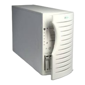
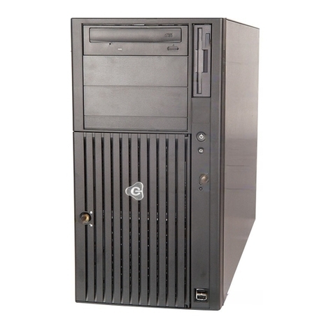
Gateway 8400 User guide

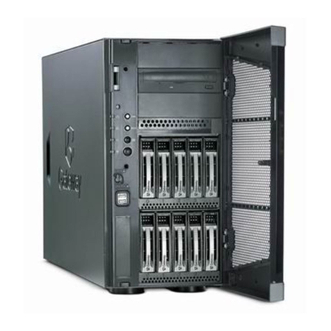
8400 Server
System Manual
A MAN US 8400 SYS GDE R0 5/00

i
Contents
Preface..............................................................v
Conventionsusedinthismanual .......................................v
Getting additional information . . . .......................................vii
1 System Features ................................................1
Standardfeatures ...................................................1
Front panel ........................................................2
Back panel ........................................................4
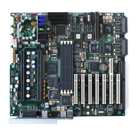
Systemboard ......................................................6
2 System Setup ...................................................9
Setting up your system . . .............................................9
Starting your system ................................................10
Understanding the Power-On Self-Test ..............................11
Setting up the operating system ....................................12
Turningoffyoursystem..............................................13
Resettingyoursystem...............................................14
3 Case Access ...................................................15
Preventingstaticelectricitydischarge ...................................15
Openingthecase ..................................................17
Removing the side panels . . ......................................18
Openingthechassisbays ........................................20
Closingthecase ...................................................22
Closingthechassisbays .........................................22
Replacing the side panels . . ......................................23
4 Replacing and Adding System Components ...................25
Replacing or adding drives ...........................................25
Preparingtoreplaceoraddadrive .................................25
Drivecablingconsiderations.......................................27
The3.5-inchdiskettedrive ........................................28
The5.25-inchdevice ............................................30
SCSIharddrives................................................37
Replacing or adding memory . . . ......................................41
Replacing or adding a processor ......................................48
Adding an expansion card ............................................53
Replacingthebattery ...............................................59
05895.book Page i Thursday, May 11, 2000 1:11 PM

ii
Troubleshooting the battery installation . ..............................61
Replacing the system board ...........................................62
Replacing a hot-swap power supply ....................................64
Replacing the system fans . ...........................................67
Replacingthebezel .................................................69
Reinstallingthebezel.............................................70
5 Using the BIOS Setup Utility ....................................71
AbouttheBIOSSetuputility...........................................71
UpdatingtheBIOS ..................................................73
Settingthesystemboardjumpers ......................................74
TheCMOSClearjumper ..........................................74
PasswordClearjumper ...........................................75
BOOTOptionjumper .............................................76
BIOSrecoverymode .............................................76
6 Managing Your System .........................................79
Protectingagainstpowersourceproblems ...............................79
Surge suppressors ...............................................79
Line conditioners ................................................80
Uninterruptiblepowersupplies......................................80
Maintainingandmanagingyourharddrive ...............................81
Hard drive maintenance utility . .....................................81
Hard drive management practices ...................................82
Protectingyourcomputerfromviruses ...............................84
Systemadministrationandcontrol ......................................85
IntelServerControl(ISC) .........................................85
ManageX Event Manager .........................................85
DirectPlatformControl(DPC)Console ...............................86
Systemsecurity .................................................86
Systemrecovery ....................................................90
Creatingastartupdiskette.........................................90
Using your Server Companion CD ..................................90
7 Cleaning Your System ..........................................91
Cleaning the mouse .................................................91
Cleaning the keyboard ...............................................92
Cleaning the monitor screen ..........................................92
Cleaning the computer and monitor cases . ..............................92
05895.book Page ii Thursday, May11, 2000 1:11 PM
iii
8 Troubleshooting ................................................93
Introduction .......................................................93
Troubleshooting checklist ............................................94
Verifyingyourconfiguration .......................................94
Troubleshooting guidelines . . ......................................94
CDdriveproblems..................................................95
Harddriveproblems ................................................96
Memoryandprocessorproblems ......................................97
Modemproblems...................................................98
Peripheral/adapter problems ..........................................99
Printerproblems ..................................................101
Systemproblems..................................................103
Videoproblems ...................................................105
Errormessages ...................................................108
A Safety and Regulatory Information ............................113
B Reference Data ................................................129
Specifications.....................................................129
Systemspecifications ...........................................129
Environmentalspecifications......................................130
Index..............................................................131
05895.book Page iii Thursday, May 11, 2000 1:11 PM
iv
05895.book Page iv Thursday, May 11, 2000 1:11 PM

Conventions used in this manual v
Preface
Conventions used in this manual
Throughout this manual, you will see the following conventions:
Convention Description
ENTER Keyboard key names are printed in small capitals.
CTRL+ALT+DEL A plus sign means to press the keys at the same time.
Setup Commands to be entered, options to select, and messages that
appear on your monitor are printed in bold.
User’s Guide Names of publications are printed in italic.
Viewpoint All references to front, rear, left, or right on the computer are based
on the computer being in a normal, upright position, as viewed from
the front.
05895.book Page v Thursday, May 11, 2000 1:11 PM

vi
Important A note labeled important informs you of special
circumstances.
Caution A caution warns you of possible damage to equipment or
loss of data.
Warning A warning indicates the possibility of personal injury.
05895.book Page vi Thursday, May 11, 2000 1:11 PM

Getting additional information vii
Getting additional information
Log on to the technical support area of www.gatewayatwork.com to find
information about your system or other Gateway products. Some types of
information you can access are:
■Hardware driver and program updates
■Technical tips
■Service agreement information
■Technical documents and component information
■Frequently asked questions (FAQs)
■Documentation for peripherals or optional components
■Online technical support
05895.book Page vii Thursday, May 11, 2000 1:11 PM

viii
05895.book Page viii Thursday, May 11, 2000 1:11 PM

Standard features 1
1
System
Features
Standard features
■As many as four Intel®Pentium III®Xeon™processors with 100 MHz
Front Side Bus (FSB) in Slot 2 processor sockets
■Sixteen Dual Inline Memory Module (DIMM) sockets on a memory riser
card, that support as many as 16 GB of PC100 Synchronous Dynamic
Random Access Memory (SDRAM)
■ServerWorks ServerSet™IIIHE chipset
■PCI hot-plug controller
■Integrated Intel 82559 Fast Ethernet controller
■Integrated Adaptec AIC-7899 Dual-Channel Ultra/Ultra II/Ultra 160
(Ultra 3) SCSI controller
■Integrated Adaptec AIC-7880 narrow/wide Ultra SCSI controller
■Integrated ATI Rage IIC video controller with 2 MB of SDRAM
■Six full-length, hot-pluggable PCI slots and two half-length PCI slots
■Baseboard Management Controller (BMC) hardware management
■ATX form factor system board and pedestal chassis (convertable to
rackmount)
■One 3.5 inch 1.44 MB diskette drive and one CD drive
■Keyboard port (PS/2), mouse port (PS/2), 2 serial ports, parallel port, RJ-45
LAN port, video port, and two Universal Serial Bus (USB) ports
05895.book Page 1 Thursday, May 11, 2000 1:11 PM

2System Features
Front panel
CD drive reads data or audio CDs.
Diskette drive writes to and reads from 3.5-inch, 1.44 MB diskettes.
Door protects the external controls of the computer and the externally
accessible drives.
Door Lock controls access to the external controls and externally accessible
drives.
Drive cage door protects the hard drive cages from tampering.
Diskette drive
Power button
CD drive
Reset button
Door lock
Door (open)
Front panel LEDs
Drive cage door (open)
Sleep button
SCSI hard drive cage A
SCSI hard drive cage B
NMI reset switch
05895.book Page 2 Thursday, May 11, 2000 1:11 PM

Front panel 3
Front panel LEDs indicate the following when lit:
■Top LED - Power (steady Green when power is on, flashing Green in sleep
mode).
■2nd LED - LAN Activity (Green when LAN connection is active).
■3rd LED - HDD Activity (Green when hard drive is active).
■4th LED - Power Fault (blinking yellow when power supply fault occurs).
■5th LED - Fan Fault (steady yellow when system has a critical,
non-recoverable cooling problem, and blinking yellow when system has
a non-critical, over-temperature or low-fan-speed condition).
Hard drive cages hold five, 1-inch hot-swappable SCSI hard drives each.
NMI (Non-Masking Interrupt) reset switch is used by technicians to debug
a server having problems.
Power button turns the computer on and off. It also enables sleep-mode in
some operating systems.
Reset button restarts a system that has become non-responsive.
Sleep button initiates sleep mode to conserve power.
05895.book Page 3 Thursday, May 11, 2000 1:11 PM

4System Features
Back panel
Kensington lock slot lets you use a cable lock to secure the system and
prevent the rear access panel from being removed.
Keyboard port connects a PS/2®-compatible keyboard.
LAN connector lets you connect to an ethernet network. The adjacent
indicator LEDs show LAN activity (yellow) and 100 Mbit speed (green).
Mouse port connects a PS/2-compatible mouse.
Parallel (printer) port connects a printer or other parallel device.
Power connector connects the computer power cord. The other end of the
power cord plugs into an AC outlet or power strip.
Serial ports connect to serial devices.
Serial port A
Mouse &
Keyboard ports
Serial port B
Power connector
LAN connector
USB ports
Parallel port
Power supply
Thumbscrew Video port
Kensington
lock slot
05895.book Page 4 Thursday, May 11, 2000 1:11 PM

Back panel 5
Thumbscrew must be loosened to remove the back access panel from the
system.
USB ports connect external Plug-and-Play devices that are automatically
configured when they are plugged into the computer through one of these
ports. USB keyboards and mice are not supported, use only PS/2 versions.
Video port connects the monitor interface cable.
05895.book Page 5 Thursday, May 11, 2000 1:11 PM

6System Features
System board
ALegacy Narrow SCSI connector
BSMM (Server Monitor Module) connector
AC
D
I
J
KL
MN
O
P
Q
V
W
S
X
E
G
R
Y
Z
AA
B
F
H
T
U
AB AC
AD AE
AF AG
AH
AI
AJ
05895.book Page 6 Thursday, May 11, 2000 1:11 PM

System board 7
CLegacy Wide SCSI connector
D64-bit/33 MHz PCI slots (4)
E64-bit/66 MHz PCI slots (2)
FMemory Module connector
GHPIB (Hot Plug Indicator Board) connector
H32-bit/33 MHz half-length PCI slots (2)
IICMB (Intelligent Chassis Management Bus) connector
JVideo connector
KExternal USB ports (2)
LRJ-45 Ethernet LAN connector
MParallel connector
NSerial connectors
OKeyboard and PS/2 Mouse connectors
PInternal USB connector
QProcessor 2 VRM slot
RBattery
SProcessor 4 VRM slot
TProcessor 3 VRM slot
UProcessor 4 slot
VMain ATX Power 1 connector
WProcessor 3 slot
XAuxiliary Power connector
YProcessor 2 slot
ZMain ATX Power 2 connector
AA Processor 1 slot
AB HDD Activity connector
05895.book Page 7 Thursday, May 11, 2000 1:11 PM

8System Features
AC SMBus connector
AD Floppy Drive connector
AE IDE connector
AF Front Panel connector
AG IMB (Intra Module Bus) connector
AH Configuration Jumper J9F2 (Pins 1-3 CMOS Clear, Pins 5-7
Password Clear, Pins 9-11 Boot Option)
AI Ultra 160 SCSI A connector
AJ Ultra 160 SCSI B connector
05895.book Page 8 Thursday, May 11, 2000 1:11 PM

Settingupyoursystem 9
2
System Setup
Setting up your system
Use the instructions on the Quick Guide poster that came with your system
to assemble your system.
You can prepare a safer working environment before assembling your system
by following these guidelines:
■Use a clean, flat, and stable surface for your system. Allow at least
12 inches at the rear of the computer for cabling and air circulation.
■Obtain a grounded (three-prong) AC surge-protected power strip. A
surge-protected power strip helps protect against AC power fluctuations.
■Protect your system from extreme temperature and humidity. Do not
expose your system to direct sunlight, heater ducts, or other
heat-generating objects.
■Keep your computer away from equipment that generates magnetic
fields, such as unshielded stereo speakers. Even a telephone placed too
close to the computer may cause interference.
■Plug the computer into a wall outlet or power strip that is easily
accessible.
Important Keep the computer boxes and packing material in case
you need to send the computer to Gateway for repairs. If
you return your computer in different packaging, your
warranty may be voided.
05895.book Page 9 Thursday, May 11, 2000 1:11 PM

10 System Setup
Starting your system
Before you start your system for the first time:
■Make sure all cables are firmly connected to the proper ports on the back
panel of the computer.
■Make sure the computer and monitor are plugged into an AC outlet or
power strip and that the power strip is turned on.
To start the system:
1If you have connected the system components to a power strip, make
sure all the system components are turned off, then turn on the power
strip.
2Turn on the monitor.
Caution Make sure your computer and peripherals are turned off
and unplugged from the power outlet when you connect
peripherals to the computer, or you might damage the
computer or the peripherals.
05895.book Page 10 Thursday, May 11, 2000 1:11 PM

Starting your system 11
3Turn on the computer. The top light-emitting diode (LED) at the right
side of the bezel is lit when the power is on.
4Turn on any other components connected to the computer, such as
speakers, a printer, or a scanner.
If nothing happens when you turn on the system:
■Make sure the power cables are securely plugged in and that your
power strip (if you are using one) is plugged in and turned on.
■Make sure the monitor is connected to the computer, plugged into
the power strip or AC outlet, and turned on. You may also need
to adjust the brightness and contrast controls on the monitor.
Understanding the Power-On Self-Test
When you turn on your computer, the power-on self-test (POST) routine
checks the system memory and components. If POST finds any problems, the
system displays error messages. Write down any error messages that you see.
If you continue to have problems, these error messages may help technical
support diagnose the cause.
Power button
Power LED
05895.book Page 11 Thursday, May 11, 2000 1:11 PM
Other manuals for 8400
1
Table of contents
Other Gateway Server manuals

Gateway
Gateway 980 User manual

Gateway
Gateway ALR 8200 Assembly Instructions

Gateway
Gateway 920 User manual

Gateway
Gateway E-9520T User manual

Gateway
Gateway 995 User manual

Gateway
Gateway 9510 User manual

Gateway
Gateway 7400 User manual

Gateway
Gateway ALR 8200R User manual

Gateway
Gateway ALR 7200 Assembly Instructions

Gateway
Gateway 9315 User manual

Gateway
Gateway 920 User manual

Gateway
Gateway 8450R User guide

Gateway
Gateway 960 User manual

Gateway
Gateway 9715 User manual

Gateway
Gateway E-9722R User manual

Gateway
Gateway 7210 User guide

Gateway
Gateway 935 series User manual

Gateway
Gateway ALR 7200R User manual

Gateway
Gateway E-9220T User manual

Gateway
Gateway 7450R User guide