GATEWORKS Venice GW7100 User manual

Venice Single Board Computer Operating Manual
TABLE OF CONTENTS
TABLE OF CONTENTS 2
INTRODUCTION 4
Product Description 4
Standard Features 4
Ordering Options – Standard Configuration* 5
Ordering Options – Accessories 5
Feature Locations 6
Functional Blocks 8
ARMv8 Processor 9
DDR4 SDRAM 9
System Flash 9
Mini-PCIe Sockets 9
USB Support 9
PCIe Socket Reset & WiFi Disable 10
Nano SIM Expansion 10
GbE Ethernet 10
USB Ports 10
Peripheral Expansion 11
Digital I/O 11
Serial I/O 11
Analog Input 11
System Reset 11
I2C Two Wire Interface 11
SPI Serial Peripheral Interface 11
Gateworks System Controller 12
Real Time Clock with Battery Backup 12
System Temperature and Voltage Monitor 12
Configuration EEPROM 13
Additional System Level Functions 13
Battery Backup 13
3-Axis Accelerometer/Magnetometer 14
Optional GPS Receiver 14
JTAG Programming Port 15
Status LEDs 15
Power Architecture 16
Barrel Jack Power 16
Passive Power over Ethernet 16
Switching DC/DC Regulators 16
CONNECTORS 18
Cellular Nano SIM Expansion Socket (J1) 18
USB Type C Connector (J2) 18
Optional GPS MMCX or u.FL Antenna (J3) 18
GATEWORKS.COM 3026 S. Higuera St San Luis Obispo, CA 93401 P:(805)781-2000
2 of 27

Venice Single Board Computer Operating Manual
Peripheral Expansion (J4) 19
Mini-PCIe (J6) 19
SOM Header (J7 & J9) 20
Test Header (J8) 20
Battery Coin Cell Socket (J12) 20
Gigabit Ethernet Port and Passive PoE Input Power (J13) 20
Optional GbE Ethernet RJ45 Replacement Header (J14) 21
Input Power Header (J15) 21
JTAG Programming and Serial Console (SOM J4) 21
SOFTWARE 23
Getting Started 23
Gateworks System Controller 23
JTAG Programming 23
Manufacturer's Website Links / Support Mailing List 24
SPECIFICATIONS 25
Electrical 25
Environmental 25
Mechanical 25
CUSTOMER SUPPORT 28
Product Revision History 28
Technical Assistance 28
Warranty 28
Return for Repair 28
Life Support Policy 29
Copyright & Trademarks 29
GATEWORKS.COM 3026 S. Higuera St San Luis Obispo, CA 93401 P:(805)781-2000
3 of 27

Venice Single Board Computer Operating Manual
1. INTRODUCTION
1.1. Product Description
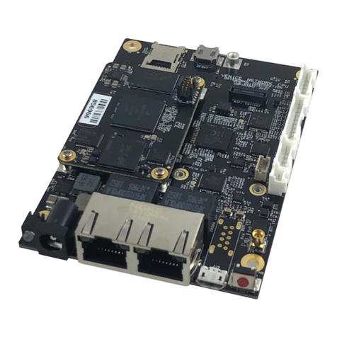
The GW7100-00 is a member of the Gateworks 7th generation Venice family of single
board computers targeted for rugged and industrial embedded applications. The
GW7100-00 features the 64-bit NXP™ i.MX8M Mini Quad Core ARM ® Cortex™-A53
SoC processor operating at 1.6GHz, 1GBytes of LPDDR4 DRAM, and 8GBytes of
eMMC System Flash. A single Mini-PCIe expansion socket can be used for PCI
Express peripherals such as 802.11ax/ac/b/g/n WiFi radios, 5G/4G/3G/CATM1 cellular
modems. Peripheral headers support Digital I/O, Analog Input, UART/TTL Serial, I2C
and SPI. A Nano SIM slot is standard for cellular modems. A 3-Axis accelerometer is
standard. An optional GPS is available. The Gateworks System Controller provides
embedded features such as real time clock, voltage and temperature monitor,
programmable pushbutton, and programmable board shut-down and wake-up for
remote applications. A wide-range DC input power supply provides up to 15W of power.
Power is applied through a dedicated header or an Ethernet port in a passive Power
over Ethernet (PoE) architecture. Ubuntu Linux BSP is supported.
1.2. Standard Features
● NXP™ 64-bit i.MX8M Mini 1.6GHz Quad Core ARM® Cortex™-A53 SoC Processor
● 1GByte LPDDR4 DRAM Memory
● 8GBytes eMMC Flash System Memory
● One High-Power Gen 2 Mini-PCIe Socket with USB 2.0 and Nano SIM
● One GbE Ethernet Port supporting Passive PoE
● Optional u-blox GPS with MMCX Antenna Connector
● Digital I/O & Analog Port, I2C & SPI Port
● UART TTL Serial Port
● USB 2.0 Type-C Port
● Digital 3-axis MEMS Accelerometer
● Real Time Clock with Battery Backup
● Voltage and Temperature Monitor
● Serial Configuration EEPROM
● Programmable Watchdog Timer
● 8 to 60VDC Input Voltage Range
● Power Through Dedicated Connector or Ethernet with Passive PoE
● 6W@25°C Typical Operating Power
● 9W Available for Mini-PCIe Socket
● Reverse Voltage Protection
● -40°C to +85°C Operating Temperature
● Ubuntu Linux Board Support Package
● 1 Year Warranty
GATEWORKS.COM 3026 S. Higuera St San Luis Obispo, CA 93401 P:(805)781-2000
4 of 27

Venice Single Board Computer Operating Manual
1.3. Ordering Options – Standard Configuration*
Order Code
ARMv8
processor
SDRAM
Flash
Operating
Temp
Peripherals
GW7100-00
Quad Core @
1.6GHz
1GByte
8GBytes
-40℃ to
+85℃
Standard
GW7100-01
Quad Core @
1.6GHz
4GByte
64GBytes
-40℃ to
+85℃
Standard
GW7101-00
Quad Core @
1.6GHz
1GByte
8GBytes
-40℃ to
+85℃
+GPS
GW7101-01
Quad Core @
1.6GHz
4GByte
64GBytes
-40℃ to
+85℃
+GPS
* Contact factory for different configurations of CPU, DRAM, Flash, and support
peripherals
1.4. Ordering Options – Accessories
Order Code
Description
GW11033
USB JTAG Programmer 10-pin Kit (Contains GW16099)
GW10054
Gigabit PoE Injector
GW10030
24V Supply
GW11047
Development Kit, Includes GW7100 SBC
GATEWORKS.COM 3026 S. Higuera St San Luis Obispo, CA 93401 P:(805)781-2000
5 of 27

Venice Single Board Computer Operating Manual
1.5. Feature Locations
Top Side Features
GATEWORKS.COM 3026 S. Higuera St San Luis Obispo, CA 93401 P:(805)781-2000
6 of 27

Venice Single Board Computer Operating Manual
Bottom Side Features
GATEWORKS.COM 3026 S. Higuera St San Luis Obispo, CA 93401 P:(805)781-2000
7 of 27

Venice Single Board Computer Operating Manual
1.6. Functional Blocks
The functional block diagram is shown below followed by a detailed description of each
major functional block.
Functional Block Diagram
GATEWORKS.COM 3026 S. Higuera St San Luis Obispo, CA 93401 P:(805)781-2000
8 of 27

Venice Single Board Computer Operating Manual
ARMv8 Processor
The 64-bit NXP™ i.MX8M Mini Quad Core ARM® Cortex™-A53 SoC processor
includes many peripherals for supporting secure network and multimedia processing
and connectivity in small embedded applications.
● Quad Cortex-A53 processing cores
● Core operating frequency of 1.6GHz
● DDR4 SDRAM supports up to 2133MTps data rate
● Interfaces include Gigabit Ethernet, PCIe Gen2, and USB 2.0
● Peripheral interfaces include eMMC, SPI, I2C, UART, and GPIO
● Integrated acceleration for security
● Integrated 2D & 3D GPU (1x shader, OpenGL®ES 2.0)
● MIPI Display DSI & Camera CSI
● 1080p60 Encoder and Decoder
● IEEE1588 precision stamp protocol support
DDR4 SDRAM
The SDRAM resides in one LPDDR4 device soldered directly to the board. This
architecture supports DDR4 memory capacities from 1GByte to 4GBytes. The 32-bit
DDR4 interface operates at up to 1500MHz for supporting fast data transfer rates. The
factory default includes 1GByte of LPDDR4.
System Flash
The System Flash supports eMMC memory capacities from 4GBytes to 64GBytes. The
8-bit data bus interface supports double data transfer rates. The default boot device is
the eMMC Flash. The factory default is 8GBytes.
Mini-PCIe Sockets
Mini-PCIe is a small form factor PCI card that uses the same signal protocol, electrical
specifications, and configuration definitions as conventional PCI Express. The board
includes Gen 2 capable Mini-PCIe sockets with the following enhancements to the PCI
Express standard.
● The 3.3V power for the socket is increased from a maximum of 3.3W to 8W for
accommodating higher power radios. The 8W limit is due to the 0.5A limit of the
individual socket pins.
● The PCIe reset for the socket is unique and under software control.
● Certain sockets support both PCIe and USB 2.0 signaling
USB Support
● Slot J6 Supports PCIe, USB 2.0, SIM
GATEWORKS.COM 3026 S. Higuera St San Luis Obispo, CA 93401 P:(805)781-2000
9 of 27

Venice Single Board Computer Operating Manual
PCIe Socket Reset & WiFi Disable
The Mini-PCIe sockets support individual software programmable resets and shared
WiFi disable signals. The reset signal is controlled through the processor PCIe
interface and the WiFi disable signal is controlled through the Gateworks System
Controller.
Nano SIM Expansion
A Nano SIM socket extends the functionality of the SBC.
The Nano SIM (4FF) socket accepts 12.3 mm by 8.8 mm cellular SIM cards. The SIM
signals are routed to a single Mini-PCIe socket for cellular modem usage.
GbE Ethernet
The SBC supports Gigabit Ethernet. The Ethernet ports operate in a 10BASE-T,
100BASE-TX or 1000BASE-T configuration and include auto MDI/MDIX for
automatically switching data receive and data transmit pairs. Additional features include
full-duplex operation as well as support for auto- negotiation. The data interfaces
include direct-touch ESD protection that exceeds IEC61000-4-2-ESD. The Ethernet
MAC addresses are programmed into the Gateworks System Controller Configuration
EEPROM during automated factory testing.
The IEEE802.3 compliant Ethernet MAC Media Access Controllers are located in the
processor. The Gigabit Ethernet Port MAC communicates to an external PHY physical
layer device through an RGMII interface. The external PHY is reset under software
control using a processor digital I/O signal.
The RJ45 connector for the Gigabit Ethernet Port includes integrated status lights. The
green light is on for link and blinking for activity. The yellow status light indicates speed.
The yellow light is off for both 10Mbps and 100Mbps, and on for 1000Mbps.
The SBC input power can be provided through the Gigabit Ethernet Port jack in a
Passive Power over Ethernet architecture. This is discussed in greater detail at the end
of this section. The RJ45 connectors can be replaced with a header as an ordering
option.
USB Ports
The processor includes two USB ports. The default processor supports USB 2.0. Future
SOMs may support USB 3.0. One port is connected to a USB Type-C connector and the
other to a Mini-PCIe socket. The USB ports support low-speed 1.5Mbps transfers,
full-speed 12Mbps transfers, and high- speed 480Mbps transfers. The SBC is
configured as a Downstream Facing Port capable of sourcing 5V at 1.5A. The output
power is enabled through a CPU GPIO signal (GPIO[1]:DIO[12]) and the current fault
monitoring is monitored through another CPU GPIO signal (GPIO[1]:DIO[13]).
GATEWORKS.COM 3026 S. Higuera St San Luis Obispo, CA 93401 P:(805)781-2000
10 of 27

Venice Single Board Computer Operating Manual
Peripheral Expansion
The SBC includes a peripheral expansion connector that supports digital I/O, serial I/O,
analog input, system reset, I2C and power.
Digital I/O
There are several general purpose digital I/O signals supported with CPU GPIO
digital I/O signals. The 3.3V digital I/O signals support 10mA drive current, 10mA
sink current, and signal conditioning in the form of a series 332 ohm resistor.
Serial I/O
The serial interface is available through several UARTs as defined in the
connector section in this document. One UART is routed out of a 20-pin I/O
connector. Another UART is routed to the optional GPS.
Analog Input
There is one analog inputs that is available through the Gateworks System
Controller. The 0 to 5V analog input is divided by two.
System Reset
The system reset signal is connected to the Gateworks System Controller
pushbutton input and supports all of the associated features. This includes
generating an interrupt, system reset, and powering the SBC on and off. This
signal can be found on the 20-pin I/O connector.
I2C Two Wire Interface
An I2C interface is offered.The 3.3V two wire interface supports standard
SCL/SDA protocols up to 400KHz with 7-bit and 10-bit addressing in both master
and slave operation. The two wire interface is supported with the processor port
and includes pull up resistors on both signals.
More information can be found at the following links:
●http://trac.gateworks.com/wiki/I2C
SPI Serial Peripheral Interface
An SPI serial peripheral interface is available through the 20-pin I/O connector.
The interface operates up to 50MHz, and supports both interrupt and polled
transactions.
More information can be found at the following links:
●http://trac.gateworks.com/wiki/SPI
Gateworks System Controller
The GSC Gateworks System Controller is a custom battery-backed micro-controller
designed by Gateworks to implement many of the embedded features found on the
board. This includes features such as real time clock with battery backup, system
temperature and voltage monitor, configuration EEPROM, and digital I/O. Software
information can be found at http://trac.gateworks.com/wiki/gsc
GATEWORKS.COM 3026 S. Higuera St San Luis Obispo, CA 93401 P:(805)781-2000
11 of 27

Venice Single Board Computer Operating Manual
Real Time Clock with Battery Backup
The real time clock is provided by the Gateworks System Controller. The
Gateworks System Controller emulates an industry standard Dallas
Semiconductor DS1672 to support the real time clock. This includes a 32-bit
counter that counts seconds for determining time of day, week, month, and year.
The I2C address for the real time clock is 0x68h. The real time clock is battery
backed to retain time information when power is removed from the board. The
battery is a 6.8mm MS621T rechargeable coin cell installed in a surface mount
socket.
System Temperature and Voltage Monitor
The system temperature and voltage monitor is provided by the Gateworks
System Controller. The Gateworks System Controller does not emulate a specific
device to support the temperature and voltage monitoring functions. The I2C
address for the temperature and voltage monitor is 0x29h. The temperature and
voltage parameters monitored by the Gateworks System Controller are listed in
the table below. The GSC mapping includes the value referenced by the software
driver written for the Gateworks System Controller. Software information is
available on the following Gateworks Wiki page:
http://trac.gateworks.com/wiki/gsc
Analog
Input
Input Divider
R1/(R1+R2)
Description
0
10K/10K
Board Level Operating Temperature
1
22.1K/1K
Board Level Input Operating Voltage
2
10K/10K
ADC1
3
N/A
N/A
4
None
1.1V MX8M Mini DRAM
6
None
1.2V Core Mipi
7
None
1.0V RGMII Phy
8
10K/10K
2.5V RGMII Phy
9
10K/10K
3.3V Primary Supply
12
None
0.95V CPU
13
None
1.8V LPDDR4
14
None
Reserved
15
None
Reserved
Gateworks System Controller Monitored Temperature and Voltages
Configuration EEPROM
The configuration EEPROM is provided by the Gateworks System Controller. The
Gateworks System Controller emulates an Atmel 24C04. The EEPROM is
divided into a general purpose section available to the application and a section
reserved by Gateworks for storing various system configuration parameters. The
I2C address for the configuration EEPROM is 0x50h.
GATEWORKS.COM 3026 S. Higuera St San Luis Obispo, CA 93401 P:(805)781-2000
12 of 27

Venice Single Board Computer Operating Manual
Additional System Level Functions
The Gateworks System Controller also supports encryption key and software
programmable hardware shut-down and wake-up for the highest possible power
conservation.
Battery Backup
The Gateworks System Controller must be powered at all times if support
features such as continuous real time clock, and programmable hardware sleep
and wake-up are required. This power is supplied by a coin cell battery when the
SBC is powered down. The Gateworks System Controller seamlessly switches
from the coin cell battery to input power when the SBC is powered on to extend
coin cell battery life. The coin cell socket includes both a reverse charge
protection resistor and a current blocking diode to provide two levels of protection
required for some agency approvals.
3-Axis Accelerometer/Magnetometer
The 3-Axis sensor device combines a 8-bit linear accelerometer. The device includes a
+/-2g, +/-4g, +/-8g and +/-16g dynamically selectable acceleration full scale range.
Acceleration event functions include free fall and motion detection. The accelerometer
communicates to the CPU on the I2C[2] bus at address 0x19. The accelerometer is a
STMicroelectronics LIS2DE12TR.
More information can be found at the following links:
●https://www.st.com/en/mems-and-sensors/lis2de12.html
●http://trac.gateworks.com/wiki/accelerometer
Optional GPS Receiver
The optional u-blox ZOE-M8 GPS Receiver is a 72 channel Global Navigation Satellite
System (GNSS) device for delivering position, velocity, and time information. The GPS
Receiver includes a dual frequency RF front end for concurrent reception of up to three
GNSS systems. This includes GPS/ZQSS, GLONASS, Galileo, and BeiDou.
The device is typically configured for 9600 NMEA protocol depending on the GPS
firmware revision. Communication to the CPU through the UART1 serial port interface.
A pulse-per-second signal is also supported through the CPU GPIO[1]:DIO15 digital I/O
signal. The PPS signal can be factory optionally routed to a Mini-PCIe socket. A MMCX
or a U.FL connector connects to an externally mounted active antenna. The antenna
includes a series current limit resistor to protect against a shorted antenna.
More information can be found at the following links:
●https://www.u-blox.com/en/product/zoe-m8-series
●http://trac.gateworks.com/wiki/gps
Key Parameter
Specification
PPS Time Accuracy RMS
30nS
PPS Time Accuracy 99%
60nS
GATEWORKS.COM 3026 S. Higuera St San Luis Obispo, CA 93401 P:(805)781-2000
13 of 27

Venice Single Board Computer Operating Manual
Dynamic Operational Limit
<4G
Altitude Operation Limit
50,000m
Velocity Operational Limit
500m/s
Velocity Accuracy (50% @ 30ms)
0.05m/s
Heading Accuracy (50% @ 30ms)
0.3 degrees
GPS Receiver Key Parameters
GNSS Parameter
GPS &
Glonass
GPS
Glonass
BeiDou
Galileo
Horizontal Position Accuracy
2.5m
2.5m
4m
3m
TBD
Navigation Update Rate
ROM
Flash
10Hz
5Hz
18Hz
10Hz
18Hz
10Hz
18Hz
10Hz
18Hz
10Hz
First Fix Time
Cold Start
Hot Start
Aided Start
26s
1s
2s
29s
1s
2s
30s
1s
2s
34s
1s
3s
45s
1s
7s
Tracking Sensitivity
-167dBm
-166dBm
-166dBm
-160dBm
-159dBm
Re-acquisition Sensitivity
-160dBm
-156dBm
-156dBm
-157dBm
-153dBm
Cold Start Sensitivity
-148dBm
-145dBm
-145dBm
-143dBm
-138dBm
Hot Start Sensitivity
-157dBm
-157dBm
-156dBm
-155dBm
-151dBm
GPS Receiver GNSS Parameters
JTAG Programming Port
The primary purpose for the JTAG Port is for automated factory testing and to facilitate
downloading the application program into Flash memory. This feature requires the
GW16099 USB JTAG Programmer (sold as a GW11033 kit). The JTAG programming
port also includes a CPU UART interface in a logic-level configuration. This serial port
facilitates an operator console though the USB JTAG Programmer. Refer to Section 3
for USB JTAG Programmer instructions.
Status LEDs
The board includes a bi-color LED and optional surface mount LED located towards the
front edge of the board.
Label
Function
3.3V
Primary voltage rail is active
PRG
Programmable using i.MX8M GPIO[5]:DIO[4] and GPIO[5]:DIO[5]and
digital I/O signal
Surface Mount Status LED Functionality
GATEWORKS.COM 3026 S. Higuera St San Luis Obispo, CA 93401 P:(805)781-2000
14 of 27

Venice Single Board Computer Operating Manual
Power Architecture
DC input power is supplied through a 2-pin connector, or the Ethernet Port connector
using Passive Power over Ethernet.
2-Pin Connector Power
The 2-pin connector is at location J15 in a 1x2x2mm configuration. The input
voltage range is 8-60V. The mating connector is PAP-02V-S, available from
Digikey as part number 455-1486-ND.
Passive Power over Ethernet
The RJ45 Ethernet jack supports Full Wave Passive Power over Ethernet. This
configuration is most useful for powering the SBC through an Ethernet jack
without an 802.3at compliant PSE switch. The input voltage range is 10-60V.
The data pairs for Passive Power over Ethernet have a 0.8A current limit. It may
be necessary to increase the input operating voltage to deliver the power needed
for the Mini-PCIe radios and USB charging ports. As an example, assume the
application includes a high power radio card that requires a total of 8W and a
USB device that requires a total of 7W. The required power is 15W for the
peripherals plus 4W for the SBC. The total power requirement is approximately
21W assuming 90% efficiency for the primary power supply.
More PoE information is available on the Gateworks wiki here:
http://trac.gateworks.com/wiki/poe
Switching DC/DC Regulators
All power supply voltage rails are generated with high efficiency DC to DC
switching regulators. The SBC is classified as a SELF Safety Extra Low Voltage
Device since the maximum input voltage is below the 60VDC SELV limit as
defined by IEC 60950-1 and other standards.
Feature
Benefit
High efficiencies (up to 95%)
Reduces heat generated in enclosure
High power output (up to
30W)
Supports high power Mini-PCIe cards
Thermal shutdown
Protects against overheating
Output current limit
Protects against short circuits
Controlled startup
Reduces component stress and power surges
Common mode input filter
Reduces emissions for agency certification
Switching DC/ DC Regulator Features
GATEWORKS.COM 3026 S. Higuera St San Luis Obispo, CA 93401 P:(805)781-2000
15 of 27

Venice Single Board Computer Operating Manual
2. CONNECTORS
The board interface connector pin assignments and signal descriptions are included in
the following sections. The connectors are listed in the table below.
Connector
Populated
Function
J1
Yes
Nano SIM Socket
J2
Yes
USB Type C Socket
J3
No
Optional GPS Receiver MMCX Antenna
J4
Yes
Peripheral Expansion (GPIO, UART, I2C, SPI, ADC)
J6
Yes
Mini-PCIe Socket with PCIe and USB 2.0
J7
Yes
SOM Connector
J8
Yes
Test Header
J9
Yes
SOM Connector
J12
Yes
Coin Cell Battery Socket
J13
Yes
Gigabit Ethernet Port with Passive PoE Input Power
J14
No
Optional Ethernet Header
J15
Yes
Power Input Header
Connector Summary
Cellular Nano SIM Expansion Socket (J1)
The Nano SIM (4FF) socket accepts 12.3 mm by 8.8 mm cellular SIM cards. The SIM
signals are routed to the Mini-PCIe socket for cellular modem usage.
USB Type C Connector (J2)
The USB 2.0 port from the CPU is available through a standard Type-C connector with
the following pin assignment.
Pin
Signal
Connect
Pin
Signal
Connect
A1
GND
Ground
B12
GND
Ground
A2
TX1+
No Connect
B11
RX1+
No Connect
A3
TX1-
No Connect
B10
RX1-
No Connect
A4
VBUS
VBUS
B9
VBUS
VBUS
A5
CC1
CC1
B8
SBU2
No Connect
A6
D+
D+
B7
D-
D-
A7
D-
D-
B6
D+
D+
A8
SBU1
No Connect
B5
CC2
CC2
A9
VBUS
VBUS
B4
VBUS
VBUS
A10
RX2-
No Connect
B3
TX2-
No Connect
A11
RX2+
No Connect
B2
TX2+
No Connect
A12
GND
Ground
B1
GND
Ground
USB Type C Connector
Optional GPS MMCX or u.FL Antenna (J3)
The optional GPS feature includes an antenna connector for an externally mounted
passive or active antenna. The 50 Ohm MMCX antenna connector (standard loading
GATEWORKS.COM 3026 S. Higuera St San Luis Obispo, CA 93401 P:(805)781-2000
16 of 27

Venice Single Board Computer Operating Manual
option) is a vertical mount Molex 73415-2061, or equivalent. The 50 Ohm U.FL
connector (optional) is a vertical mount Sunridge MCBG-ST-00T, or equivalent.
Peripheral Expansion (J4)
The connector is a 20-pin header in a 2x10 configuration with 1.25mm pin spacing. The
mating connector is a JST GHDR-20V-S, available from Digi-Key as part number
455-1913-ND. The mating connector pins are JST SGHD-002GA-P0.2, available from
Digi-Key as part number 455-1914-2-ND. The digital I/O signals include signal
conditioning in the form of a series 332 ohm resistor.
Pin
Signal
1
5V
2
Ground
3
5V
4
Ground
5
3.3V
6
Ground
7
SPI_MOSI
8
SPI_MISO
9
SPI_SCLK
10
SPI_SS0
11
Serial Clock
i.MX8M I2C3 SCL
12
Serial Data
i.MX8M I2C3 SDA
13
UART[3] RXD (logic level)
14
UART[3] TXD (logic level)
15
GSC Pushbutton Interrupt
16
GSC ADC1
17
i.MX8M GPIO[1]:DIO[7]
18
i.MX8M GPIO[1]:DIO[9]
19
i.MX8M GPIO[4]:DIO[3]
20
i.MX8M GPIO[4]:DIO[4]
Digital I/O Connector
Mini-PCIe (J6)
The PCI Express Mini Card socket is an industry standard form factor.
● Slot J6 can support PCIe and USB 2.0 and SIM.
Pin
Signal
Connect
Pin
Signal
Connect
1
WAKE#
No Connect
2
3.3VAUX
3.3V
3
COEX1
No Connect
4
GND
Ground
5
COEX2
No Connect
6
1.5V
No Connect
7
CLKREQ#
No Connect
8
USIMPWR
Note 2
9
GND
Ground
10
USIMDAT
Note 2
11
REFCLK-
REFCLK-
12
USIMCLK
Note 2
13
REFCLK+
REFCLK+
14
USIMRST
Note 2
15
GND
Ground
16
USIMVPP
Note 2
GATEWORKS.COM 3026 S. Higuera St San Luis Obispo, CA 93401 P:(805)781-2000
17 of 27

Venice Single Board Computer Operating Manual
17
RSVD
No Connect
18
GND
Ground
19
RSVD
No Connect
20
WDIS#
No Connect
21
GND
Ground
22
PERST#
Note 3
23
PERN0/SATA+B
Note 1
24
3.3VAUX
3.3V
25
PERP0/SATA-B
Note 1
26
GND
Ground
27
GND
Ground
28
1.5V
No Connect
29
GND
Ground
30
SMBCLK
No Connect
31
PETN0/SATA-A
Note 1
32
SMBDAT
No Connect
33
PETP0/SATA+A
Note 1
34
GND
Ground
35
GND
Ground
36
USBD-
Note 4
37
GND
Ground
38
USBD+
Note 4
39
3.3VAUX
3.3V
40
GND
Ground
41
3.3VAUX
3.3V
42
LEDWWAN#
No Connect
43
GND
Ground
44
LEDWLAN#
No Connect
45
RSVD
No Connect
46
LEDWPAN#
No Connect
47
RSVD
No Connect
48
1.5V
No Connect
49
RSVD
No Connect
50
GND
Ground
51
RSVD
No Connect
52
3.3VAUX
3.3V
Mini-PCIe Socket
SOM Header (J7 & J9)
The System on Module (SOM) with the CPU, DRAM and Flash connects to the
baseboard. There are roughly 180 pins between the 2 sockets. The system is not
designed in a way that the SOM would be removed and the user would interface with
connectors directly. If more information is required, please contact Gateworks support.
Test Header (J8)
This is for internal Gateworks use. Please contact Gateworks technical support with any
further questions.
Battery Coin Cell Socket (J12)
The 6.8mm backup battery socket allows for easy replacement of the battery. A
rechargeable 6.8mm, 3V, 3mAH Lithium coin cell should be used when replacing the
battery. Replacement batteries can be ordered from Digi-Key with part number
728-1078-ND.
Gigabit Ethernet Port and Passive PoE Input Power (J13)
The Gigabit Ethernet Ports are available through a standard 8-pin RJ45 connector. The
connector also supports Full Wave Passive Power over Ethernet. The power inputs are
diode protected to prevent back feeding with other power inputs. The Passive PoE
architecture is discussed in more detail in Section 1 and the input voltage requirements
are listed in Section 3.
Pin
Signal
Passive Power
1
TX1+/RX1+
PoE V+/PoE Ground
2
TX1-/RX1-
PoE V+/PoE Ground
GATEWORKS.COM 3026 S. Higuera St San Luis Obispo, CA 93401 P:(805)781-2000
18 of 27

Venice Single Board Computer Operating Manual
3
TX2+/RX2+
PoE V+/PoE Ground
4
TX3+/RX3+
PoE V+/PoE Ground
5
TX3-/RX3-
PoE V+/PoE Ground
6
TX2-/RX2-
PoE V+/PoE Ground
7
TX4+/RX4+
PoE V+/PoE Ground
8
TX4-/RX4-
PoE V+/PoE Ground
GbE Ethernet Port Connector
Optional GbE Ethernet RJ45 Replacement Header (J14)
The Ethernet port is optionally available through an 8-pin header in a 1x8 configuration
with 1.25mm pin spacing. The mating connector is a Molex Picoblade 51021-0800,
available from Digi-Key as part number WM1726-ND. The mating connector pins are
Molex 50058-8100, available from Digi-Key as 50058-8100-ND. Contact the factory for
additional information on this option.
Input Power Header (J15)
Power is normally applied to the SBC through a latching 2-pin connector in a
1x2 configuration with 2mm spacing or through the Gigabit Ethernet Port
connector in a Passive Power over Ethernet configuration. The 2-pin mating
connector is a JST PAP-02V-S, available from Digi-Key as part number 455-
1486-ND. The mating connector pins are JST SPHD-002T-P05, available from
Digi-Key as part number 455-1313-1-ND.
Pin
Signal
1
8-60VDC Positive
2
Ground
Input Power Connector
JTAG Programming and Serial Console (SOM J4)
The JTAG programming port and serial console port are both available through a single
10-pin header in a 2x5 configuration with 0.05-inch pin spacing. The mating cable is a
Samtec FFSD series, or equivalent. For example the FFSD-05-S-05.00-01-N is a 5-inch
ribbon cable with a mating connector on one end.
The primary purpose for the JTAG Port is for automated factory testing and to facilitate
downloading the application program into Flash memory. This feature requires the
GW16099 USB JTAG Programmer. The JTAG programming port also includes the CPU
UART[2] interface in a logic-level configuration. This serial port facilitates an operator
console though the USB JTAG Programmer. See ordering options for more information.
Refer to Section 3 for USB JTAG Programmer instructions.
Pin
Signal
Pin
Signal
1
JTAG TRST
2
3.3V
3
JTAG TDI
4
Ground
5
JTAG TMS
6
UART[2]:TXD (logic level)
GATEWORKS.COM 3026 S. Higuera St San Luis Obispo, CA 93401 P:(805)781-2000
19 of 27

Venice Single Board Computer Operating Manual
7
JTAG TCK
8
UART[2]:RXD (logic level)
9
JTAG TDO
10
System Reset
JTAG Programming Port and Serial Console Connector
GATEWORKS.COM 3026 S. Higuera St San Luis Obispo, CA 93401 P:(805)781-2000
20 of 27
Table of contents
Other GATEWORKS Single Board Computer manuals

