gaviota PARABOX User manual

Manual de Instalación
E
Installation Manual
FManuel d’Installation
GB Manuale di Installazione
I
PARABOX

2
PARABOX
E
Leer detenidamente estas instrucciones de montaje antes de cualquier uso y conservarlas después de la instalación.
El no respetar las instrucciones de montaje, uso y especificaciones técnicas del artículo, así como excederse en los rangos de uso
máximos especificados (pesos, etc...), significará la exclusión de la Política de Garantía y de Servicio Postventa de Gaviota Simbac, S.L.
GB
Read these assembly instructions carefully before use and keep them after installation.
Failing to follow the assembly instructions, use instructions and technical specifications of the product, as well as surpassing the specified
maximum range (weight, etc.) will void the Guarantee Policy and After-Sales Service of Gaviota Simbac, S.L.
Lire attentivement les présentes instructions de montage avant toute utilisation et les conserver après l’installation.
Le non-respect des instructions de montage, d’utilisation et de spécifications techniques de l’article, tout comme l’excès des portées d’utilisation
maximales spécifiées (poids, etc.) équivaudra à l’exclusion de la Politique de Garantie et de Service Après-vente de Gaviota Simbac, S.L.
F
Leggere attentamente il presente manuale contenente le istruzioni di montaggio prima di procedere all’uso. Conservare il manuale per
riferimento futuro.
Il mancato rispetto delle istruzioni, dell’uso corretto e delle specifiche tecniche così come delle misure massime indicate (peso,...), implicherà
l’esclusione dalla Politica di Garanzia e dal Servizio Postvendita di Gaviota Simbac, S.L.
I
Advertencias de seguridad
E
Safety warnings
FAvertissement de sécurité
GB Avvertenza di sicurezza
I

3
PARABOX
02
Descuentos • Cutting
Réductions • Misure
03
Preparación en fábrica • Assembly at the factory
Préparation à l’usine • Preparazione in fabbrica
Índice • Index • Index • Indice
Identificación de las piezas • Part identification
Identification des pièces • Identificazione dei pezzi
01
04
Instalación en obra • Built-in installation
Installation dans les travaux • Installazione in loco

4
PARABOX
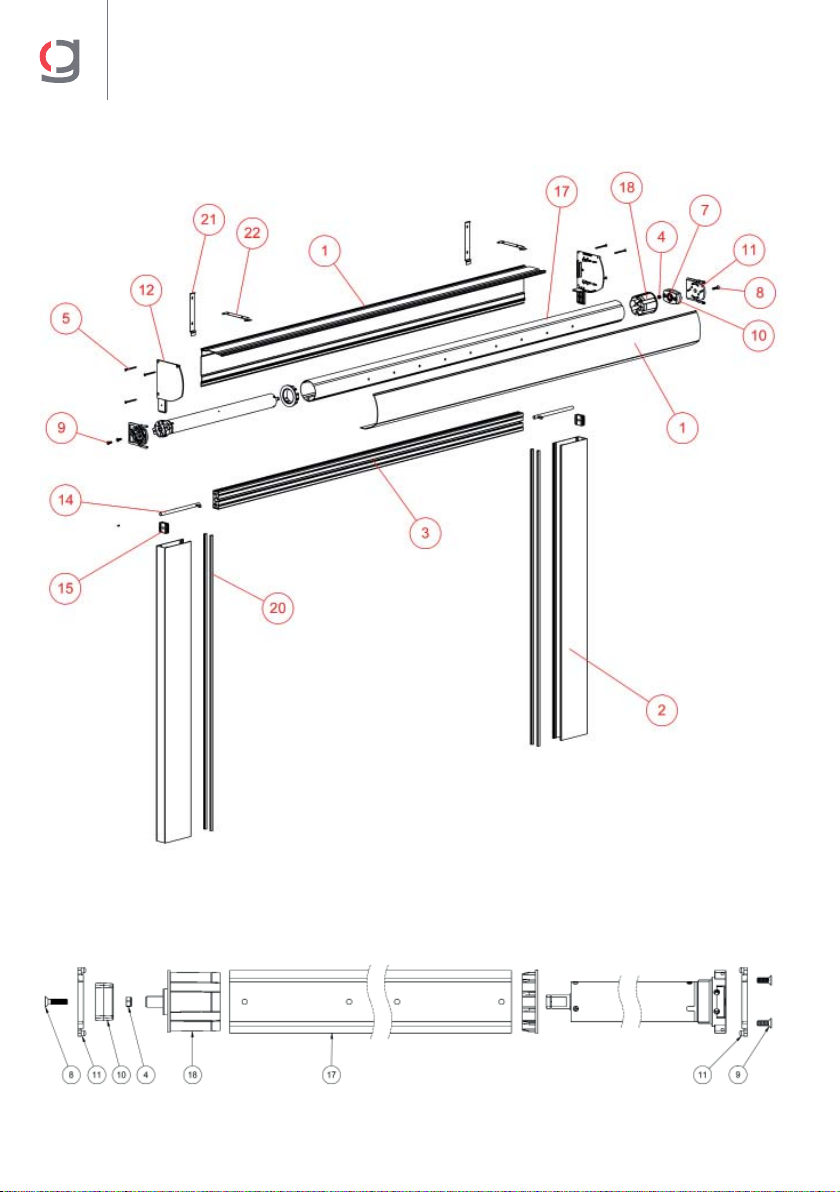
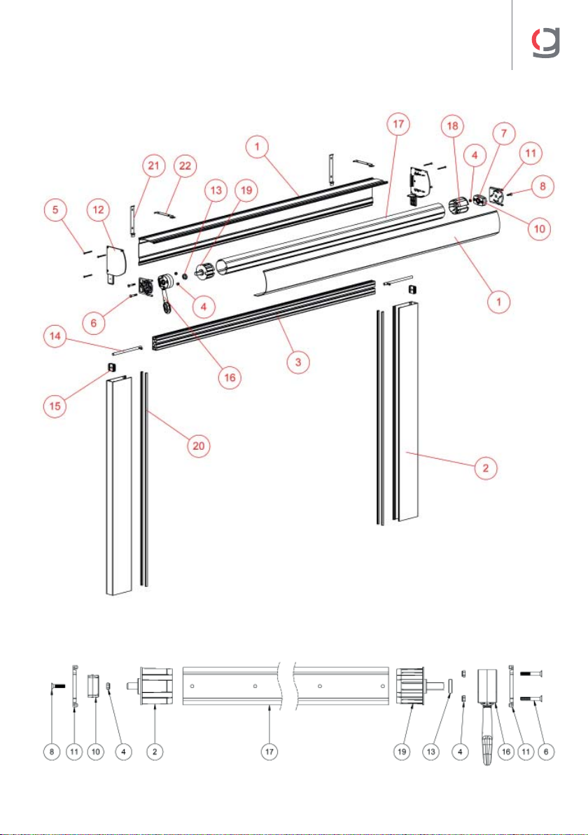
01
Identificación de las piezas • Part identification
Identification des pièces • Identificazione dei pezzi
Numero • Number
Numéro • Numero
Código • Code
Code • Codice
Descripción • Description
Description • Descizione
PERFILES • PROFILES • PROFILÉS • PROFILI
1 80141619
Mts. juego perfiles cofre Parabox blanco 5m
Set of box profiles, Parabox, 5m, white
Jeux profilés core Parabox blanc 5 m
Metri di gioco profili cassonetto Parabox bianco 5m
2 80141303
Mts. perfil guía Paravento blanco 5m
Set of guide profiles, Parabox, 5m, white
Profilé glissière Paravento blanc 5 m
Metri profilo guida Paravento bianco 5m
3 80140362
Mts. perfil faldón cortavientos blanco 5m
Windbreaker valance profile, 5m, white
Profilé chasse-pieds brise-vent blanc 5 m
Metri profilo rivestimento antivento bianco 5m
80170507 KIT TAPAS CAJÓN PARABOX • PARABOX BOX COVER SET
KIT COUVERCLE CAISSON PARABOX • KIT TAPPI CASSONETTO PARABOX
4 40051155
Tuerca autoblocante M6 DIN 985 Dacro
M6 DIN 985 Dacro locknut
Écrou autobloquant M6 DIN 985 Dacro
Vite filettata autobloccante M6 DIN 985 Dacro
5 40051158
Tornillo rosca chapa 4,2x38 DIN 7982
4,2x38 DIN 7982 Self-drilling screw
Vis à tôle 4,2 x 38 DIN 7982
Bullone filettato lamina 4,2x38 DIN 7982
6 40051160
Tornillo 6x40 DIN 7991 Dacro
6x40 DIN 7991 Dacro screw
Vis 6x40 DIN 7991 Dacro
Bullone 6x40 DIN 7991 Dacro
7 40051269
Rodamiento Ø28 pista metal R-12 R-122 (H-8) tipo Z
R-12 R-122 (H-8) Z type Ø28 metal roller bearing
Palier Ø28 piste métal R-12 R-122 (H-8) type Z
Cuscinetto a sfera Ø28 pista in metallo R-12 R-122 (H-8) tipo Z
8 40051415
Tornillo Allen M6x25 DIN 7991 Dacro
M6x25 DIN 7991 Dacro Allen screw
Vis Allen M6 x 25 DIN 7991 Dacro
Bullone Allen M6x25 DIN 7991 Dacro
9 40051139
Tornillo con avellanado Philips M6x16 DIN 965 Dacro
M6x16 DIN 965 Dacro Phillips screw
Vis avec fraisage Philips M6 x 16 DIN 965 Dacro
Vite a testa svasata Philips M6x16 DIN 965 Dacro
10 40061284
Soporte punto rodamiento H=20mm blanco
Ball bearing support H=20mm, white
Support point palier H=20 mm blanc
Supporto punto cuscinetto a sfera H=20mm bianco
11 40061354
Soporte interior cofre Keeper blanco
Inner support for Keeper box, white
Support intérieur core Keeper blanc
Supporto interno cassonetto Keeper bianco

5
PARABOX
Numero • Number
Numéro • Numero
Código • Code
Code • Codice
Descripción • Description
Description • Descizione
12 45036151
Juego testeros Keeper con acople blanco
Set of end caps for Keeper, white
Jeux consoles Keeper avec fixation blanche
Gruppo telaio Keeper con sistema di aggancio bianco
13 80170194
Anillo compensación Q13 1415 Screen Universal Zip
Q13 1415 Trim ring Universal Zip Screen
Anneau compensation Q13 1415 Screen Universal Zip
Anello di compensazione Q13 1415 Screen Universal Zip
ELEMENTOS FUERA DE KIT • ITEMS NOT INCLUDED IN THE KIT
ÉLÉMENTS EXTÉRIEURS DU KIT • ELEMENTI NON INCLUSI NEL KIT
14 80140718
Cerrojillo para cortavientos D10 Inox con tornillos
Lock for D10 windbreaker, stainless steel with screws
Verrou pour brise-vents D10 Inox avec vis
Serratura per antivento D10 Inox con viti
15 80141298
Tope plástico cerrojillo Paravento
Paravento lock plastic stopper
Butée plastique verrou Paravento
Parte superiore in plastica della serratura Paravento
16 80010348
Máquina Gel 1:11 cáncamo 120 pasante blanca
Gel gear 1:11 120 eye, long screw, white
Treuil Gel 1:11 anneau 120 passant blanc
Arganello Gel 1:11 occhiello 120 passante bianca
17 80030016
Mts. tubo ranurado ojiva 70x1 5m
Galvanized round tube with ogive 70x1 5m
Tube fendu ogive 70 x 15 m
Metri tubo scanalato a ogiva 70x1 5m
18 80020038
Casquillo 70 ranurado aluminio punto E/R-12X20
Round cap of 70 mm, aluminium, E/R-12X20
Douille 70 fendue aluminium point E/R-12X20
Boccola 70 scanalata alluminio punto E/R-12X20
19 80020028
Casquillo 70 ranurado aluminio máquina E/C-13X33
Driving cap of 70 mm, aluminium, E/C-13X33
Douille 70 fendue aluminium treuil E/C-13X33
Boccola 70 scanalata alluminio meccanismo E/C-13X33
20 80141292
Rollo felpudo cortavientos Pb-90-700-4p 225m
Mat roll, windbreaker Pb-90-700-4p 225m
Rouleau tapis brise-vent Pb-90-700-4p 225m
Rullo tappetino antivento Pb-90-700-4p 225m
21 80170540
Sujeción perfil Screen Universal Zip 130 para pared
Profile fastener Universal Zip Screen 130 for wall
Fixation profilé Screen Universal Zip 130 pour mur
Sostegno profilo Screen Universal Zip 130 per parete
22 80170541
Sujeción perfil Screen Universal Zip 130 para techo
Profile fastener Universal Zip Screen 130 for ceiling
Fixation profilé Screen Universal Zip 130 pour plafond
Sostegno profilo Screen Universal Zip 130 per tetto
6
PARABOX
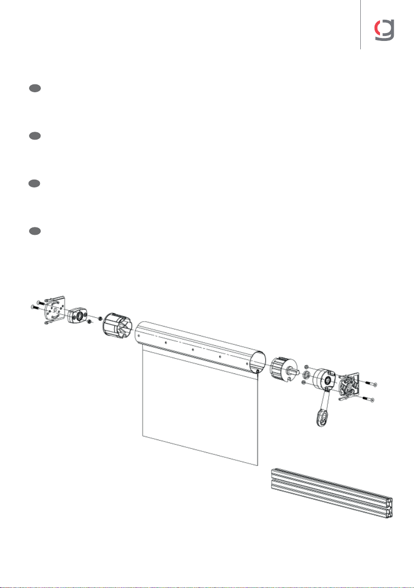
Despiece montaje con motor • Motor assembly exploded view
Découpe montage avec moteur • Esploso del montaggio con motore
Despiece eje para motor • Axis for motor exploded view
Découpe axe pour moteur • Esploso asse motore
7
PARABOX
Despiece montaje con máquina • Gear assembly exploded view
Découpe montage avec treuil • Esploso del montaggio con arganello
Despiece eje para máquina • Axis for gear exploded view
Découpe axe pour treuil • Esploso asse arganello
8
PARABOX
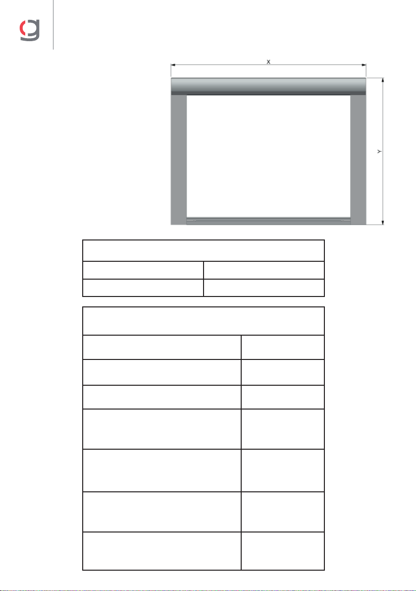
02
Descuentos • Cutting
Réductions • Misure
Rango de uso • Range of use
Portée d’utilisation • Range d’uso
x 5000 mm
y 2500 mm
Listado de descuentos • Cutting table
Liste de réductions • Elenco misure
Perfil cajón • Box profile
Profilé caisson • Profilo cassonetto X-6 mm
Perfil cajón registro • Frontal box profile
Profilé caisson chambre • Profilo cassonetto registro X-6 (+0.5/0.5) mm
Perfil guía • Guide profile
Profilé glissière • Profilo guida Y-130 mm
Perfil barra carga (montaje motor)
Charge profile (motor assembly)
Profilé barre charge (montage moteur)
Profilo barra di carico (montaggio motore)
X-90 mm
Perfil barra carga (montaje máquina)
Charge profile (gear assembly)
Profilé barre charge (montage treuil)
Profilo barra di carico (montaggio arganello)
X-100 mm
Tubo ojiva Ø70 (montaje motor)
Ø70 ogive tube (motor assembly)
Tube ogive Ø70 (montage moteur)
Tubo a ogiva Ø70 (montaggio con motore)
X-70 mm
Tubo ojiva Ø70 (montaje máquina)
Ø70 ogive tube (gear assembly)
Tube ogive Ø70 (montage treuil)
Tubo a ogiva Ø70 (montaggio con arganello)
X-105 mm

9
PARABOX
Descuentos Lona • Canvas cutting
Réduction toile • Misure tela
Descuentos lona montaje con motor
Canvas cutting for motor assembly
Réductions toile montage avec moteur
Misure tela montaggio con motore
A X-90 mm
B Y+300 mm
Descuentos lona montaje con máquina
Canvas cutting for gear assembly
Réductions toile montage avec treuil
Misure tela montaggio con arganello
A X-115 mm
B Y+300 mm
10
PARABOX
03
Preparación en fábrica • Assembly at the factory
Préparation à l’usine • Preparazione in fabbrica
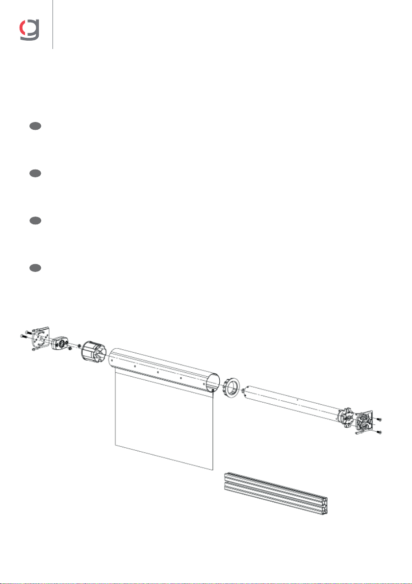
Paso 1. Introducir la lona (1) en el eje (2). Introducir el casquillo punto (3) y el anillo
motor (4). Ensamblar el soporte interior cofre (5) con el punto rodamiento (6) e introducir
en el eje. Ensamblar el soporte interior cofre (7) con el motor (8) e introducir en eje.
Introducir la barra de carga en la lona (9).
E
GB
Step 1. Insert canvas (1) in axis (2). Introduce the driving cap (3) and the motor ring (4).
Assemble the box’s inner support (5) with the ball bearing (6) and introduce in axis. Assemble
the box’s inner support (7) with the motor (8) and introduce in axis. Introduce the charge profile
in the canvas (9).
F
1. Introduire la toile (1) dans l’axe (2). Introduire la douille point (3) et l’anneau du moteur (4).
Assembler le support intérieur du core (5) avec le point palier (6) et introduire dans l’axe.
Assembler le support intérieur du core (7) avec le moteur (8) et introduire dans l’axe. Introduire
la barre de charge dans la toile (9).
I
Fase 1. Introdurre la tela (1) nell’occhiello (2). Intrdurre boccola punto (3) e anello motore
(4). Assemblare il supporto interno del cassonetto (5) al punto cuscinetto (6) e introdurre
nell’occhiello. Assemblare il supporto interno del cassonetto (7) al motore (8) e introdurre
nell’occhiello. Introdurre la barra di carica nella tela (9).
Ensamblado motor • Motor assembly
Assemblage du moteur • Assemblaggio motore
(1)
(2)
(3)
(4)
(5) (6)
(7)
(8)
(9)
11
PARABOX
Paso 1. Introducir la lona (1) en el eje (2). Introducir el casquillo punto (3) y el casquillo
maquina (4). Ensamblar el soporte interior cofre (5) con el punto rodamiento (6) e
introducir en el eje. Ensamblar el soporte interior cofre (7) con la maquina (8) e introducir
en eje. Introducir la barra de carga en la lona (9).
E
GB
Step 1. Insert canvas (1) in axis (2). Introduce the round cap (3) and the gear ring (4). Assemble
the box’s inner support (5) with the ball bearing (6) and introduce in axis. Assemble the box’s
inner support (7) with the gear (8) and introduce in axis. Introduce the charge profile in the
canvas (9).
F
1. Introduire la toile (1) dans l’axe (2). Introduire la douille point (3) et la douille treuil (4).
Assembler le support intérieur du core (5) avec le point palier (6) et introduire dans l’axe.
Assembler le support intérieur du core (7) avec le treuil (8) et introduire dans l’axe. Introduire
la barre de charge dans la toile (9).
I
Fase 1. Introdurre la tela (1) nell’occhiello (2). Introdurre la boccola punto (3) e la boccola
del arganello (4). Assemblare il supporto interno del cassonetto (5) al punto cuscinetto (6) e
introdurre nell’occhiello. Assemblare il supporto interno del cassonetto (7) al arganello (8) e
introdurre nell’occhiello. Introdurre la barra di carica nella tela (9).
Ensamblado máquina • Gear assembly
Assemblage du treuil • Assemblaggio arganello
(1)
(2)
(3)
(4)
(5)
(6)
(7)
(8)
(9)
12
PARABOX
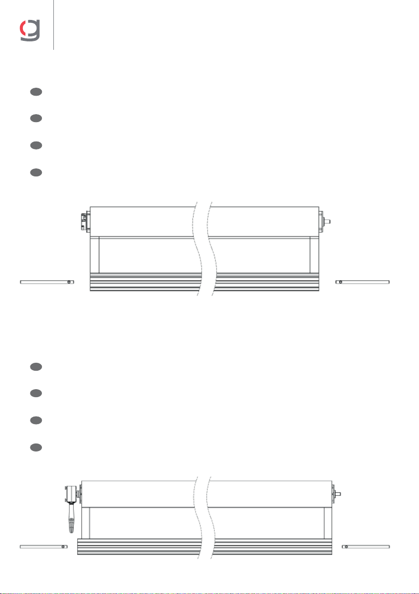
Paso 2. Alinear la barra de carga con la lona.
Introducir los cerrojillos.
E
GB
Step 2. Align the charge profile with the canvas.
Introduce the locks.
F
2. Aligner la barre de charge avec la toile.
Introduire les verrous.
I
Fase 2. Allineare la barra di carica alla tela.
Introdurre le serrature.
Para montaje con motor • For assembly with motor
Pour montage avec le moteur • Montaggio con motore
Paso 2. Desalinear la barra de carga con la lona, hacia la parte de la maquina.
Introducir los cerrojillos.
E
GB
Step 2. Unalign the charge profile with the canvas, towards the gear.
Introduce the locks.
F
2. Désaligner la barre de charge avec la toile vers la partie du treuil.
Introduire les verrous.
I
Fase 2. Inclinare la barra di carica rispetto alla tela verso la parte del arganello.
Introdurre le serrature.
Para montaje con máquina • For assembly with gear
Pour montage avec le treuil • Montaggio con arganello
13
PARABOX
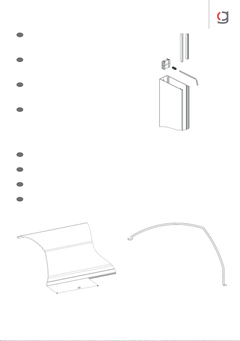
Paso 3. Introducir el tope cerrojillo (1) en
la guía (2).
Introducir los felpudos (3) la guía (2).
E
GB
Step 3. Introduce the lock caps (1) in the guide
(2).
Introduce the mat (3) in the guide (2).
F
3. Introduire la butée du verrou (1) dans la
glissière (2).
Introduire les tapis (3) de la glissière (2).
I
Fase 3. Introdurre la parte superiore della
serratura 1) nella guida 2).
Introdurre i tappetini 3) la guida (2).
(1)
(3)
(2)
Paso 4. Mecanizado perfil registro cajón.
Cortar la solapa del perfil registro cajón a las medidas indicadas.
E
GB
Step 4. Box front profile cutting.
Cut the flap of the box front profile with the indicated measures.
F
4. Mécanisation du profilé de la chambre du caisson.
Couper le rabat du profilé de la chambre du caisson selon les mesures indiquées.
I
Fase 4. Profilo meccanizzato registro del cassonetto.
Tagliare la patella del profilo registro del cassonetto in base alle misure indicate.
14
PARABOX
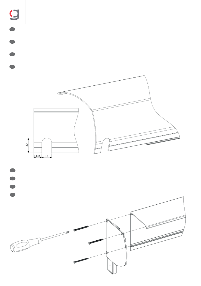
Paso 6. Ensamblado testeros. Atornillar los testeros al cajón.
E
GB
Step 6. Assembly of end caps. Srew the end caps into box.
F
6. Assemblage consoles. Visser les façades au caisson.
I
Fase 6. Assemblaggio telai. Avvitare i telai al cassonetto.
Paso 5. Mecanizado perfil registro cajón para montaje con máquina.
Realizar mecanizado a las medidas indicadas.
E
GB
Step 5. Box front profile cutting for gear assembly.
Cut with the indicated measures.
F
5. Mécanisation du profilé de la chambre du caisson pour le montage avec le treuil.
Mécanisation selon les mesures indiquées.
I
Fase 5. Profilo meccanizzato del cassonetto per il montaggio con arganello.
Installare il arganello in base alle misure indicate.
15
PARABOX
04
Instalación en obra • Built-in installation
Installation dans les travaux • Installazione in loco
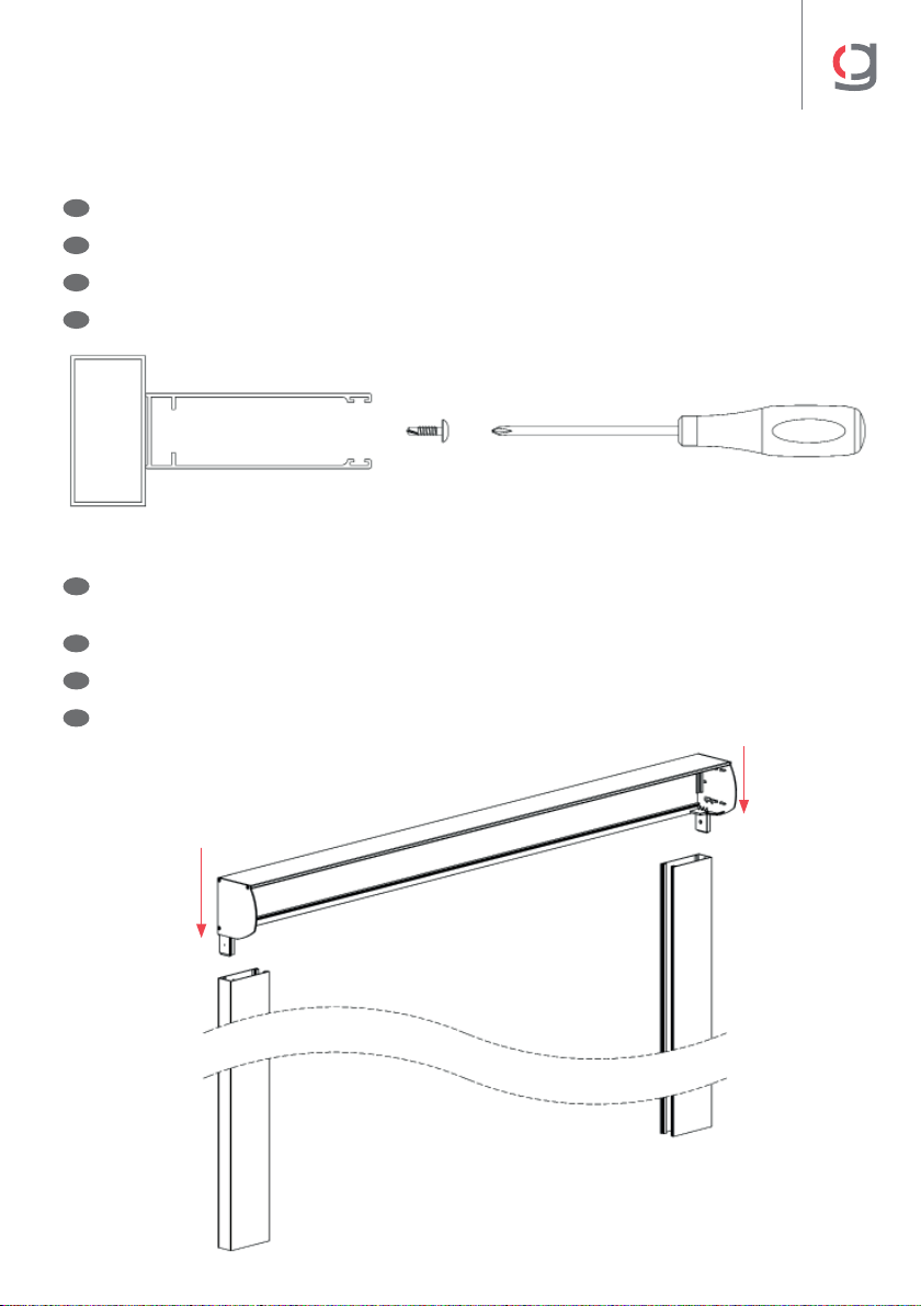
Paso 1. Atornillar las guías a la estructura. Se aconseja un tornillo cada 50 cm.
E
GB
Step 1. Screw the guides into the structure. It is recommended to use a screw every 50 cm.
F
1. Visser les glissières à la structure. Une visse est conseillée tous les 50 cm.
I
Fase 1. Avvitare le guide alla struttura. Si consiglia una vite ogni 50 cm.
Paso 2. Ensamblar el cofre en las guías, introduciendo las patas de los testeros en las
mismas.
E
GB
Step 2. Assemble the box on the guides, introducing the end caps’ flaps in the guides.
F
2. Assembler le core aux glissières en introduisant les embouts des consoles dans ces dernières.
I
Fase 2. Assemblare il cassonetto alle guide, introducendo le estremità esterne dei telai al loro
interno.

16
PARABOX
Paso 3. Introducir la barra de carga dentro de las guías y sujetar el conjunto eje en los
testeros mediante los casetes.
E
GB
Step 3. Insert the charge profile in the guides and attach the axis set to the end caps with the
cassettes.
F
3. Introduire la barre de charge dans les glissières et tenir l’ensemble de l’axe dans les consoles
par le biais de cassettes.
I
Fase 3. Introdurre la barra di carica sulle guide e sostenere l’unità asse sui telai mediante le
cassette.
Paso 4. Introducir el perfil registro en el cajón y fijar con tornillos a ambos lados.
E
GB
Step 4. Introduce the front profile in the box and attach with screws to both sides.
F
4. Introduire le profilé de la chambre dans le caisson et fixer avec des visses des deux côtés.
I
Fase 4. Introdurre il profilo registro nel cassonetto e fissare mediante viti a entrambi i lati.
(2)(1)
17
PARABOX
Instalación a pared o techo • Installation to wall or ceiling
Installation au mur ou au plafond. • Installazione a parete sul sotto
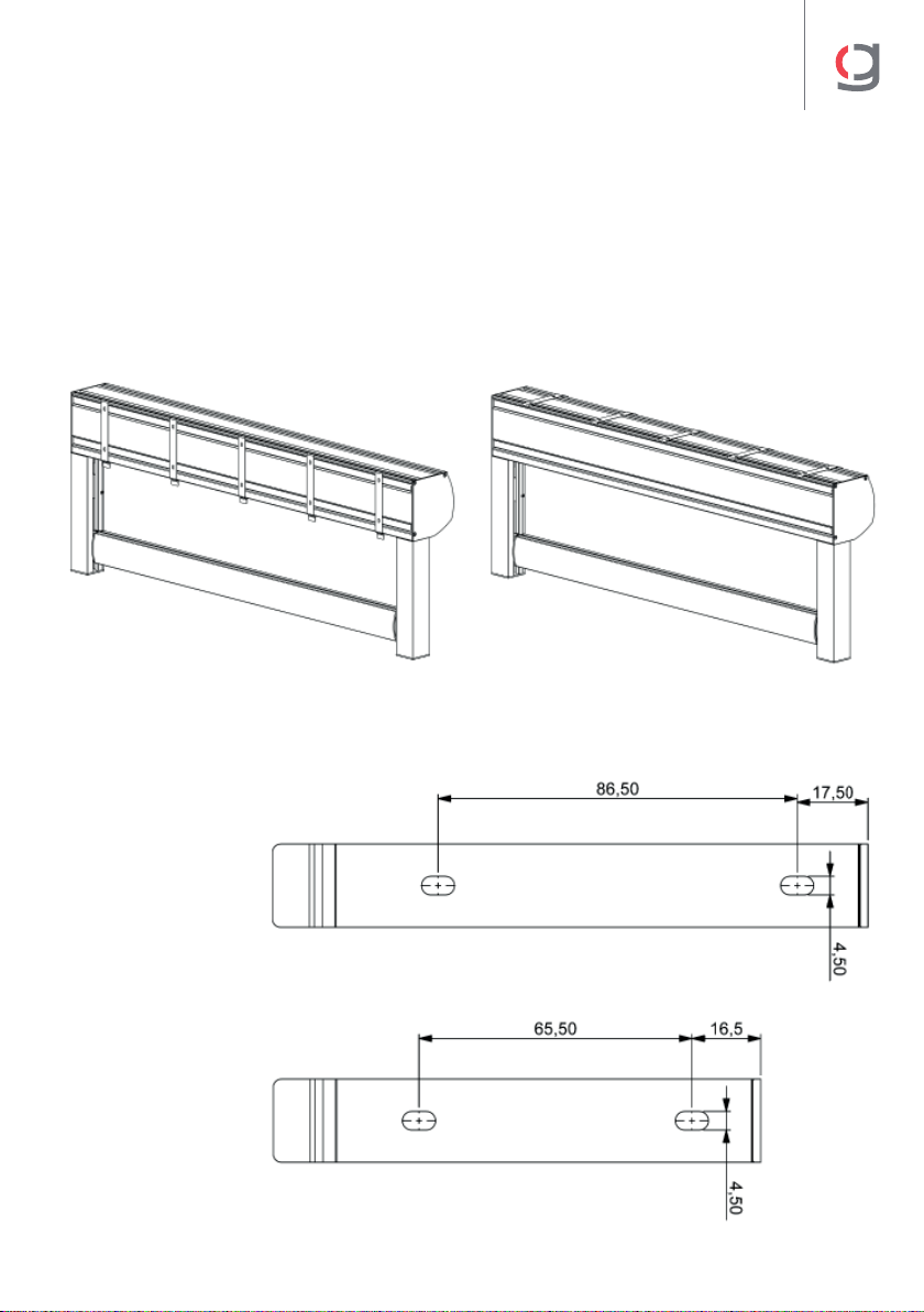
• La distancia entre soportes no debe ser superior a 750 mm.
• The distance between the supports must not be over 750mm.
• La distance entre les supports ne doit pas excéder les 750 mm.
• La distanza fra supporti non dovrà superare i 750 mm.
Medidas taladros soportes
Distance support holes
Mesures perçage supports
Misure fori supporti
18
PARABOX
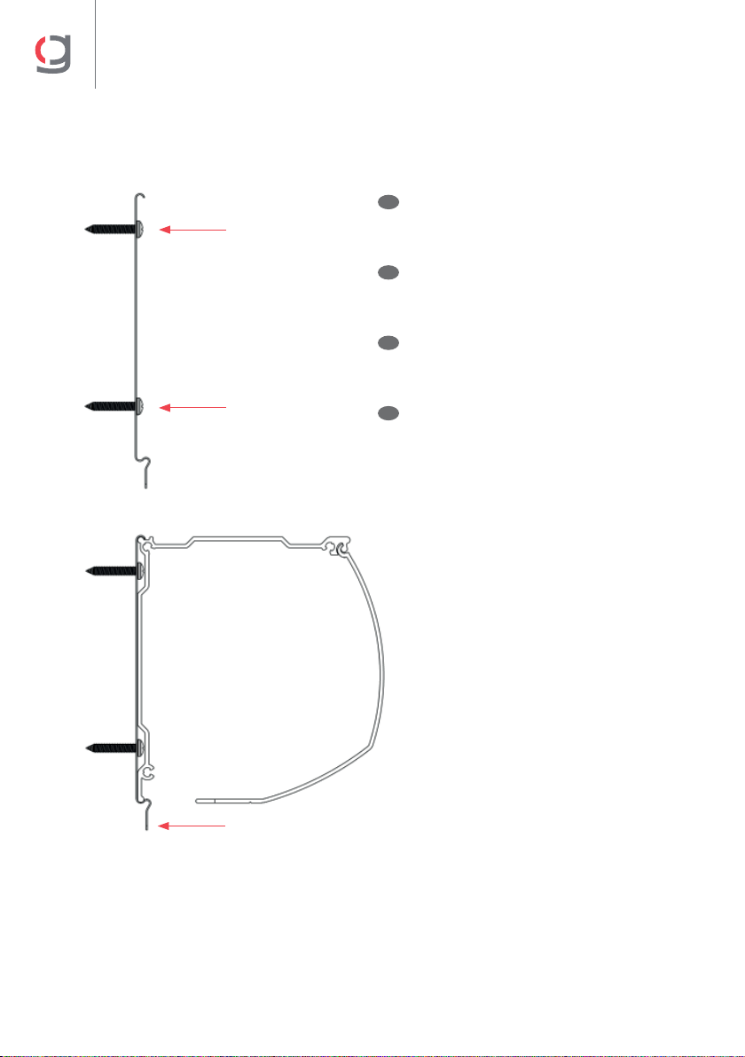
Fijación pared
Wall mount
Fixation au mur
Fissaggio a parete
Taladrar y fijar soportes (Fig. 1).
Introducir el cajón en los soportes,
presionar la patilla y soltar (Fig. 2).
E
GB
Drill and fix supports (Fig. 1). Introduce
the box on the supports, press the pin and
release (Fig. 2).
F
Percer et fixer les supports (Fig.1). Introduire
le caisson dans les supports, appuyer sur la
broche et relâcher (Fig. 2).
I
Trapanare e fissare i supporti (Fig. 1).
Introdurre il cassonetto sui supporti,
premere il perno e rilasciare (Fig. 2).
(Fig. 2)
(Fig. 1)
Presionar y soltar
Press and release
Appuyer et relâcher
Premere e rilasciare
19
PARABOX
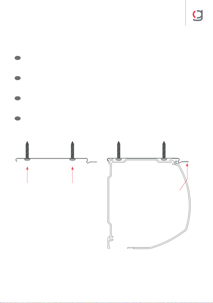
Fijación techo
Ceiling mount
Fixation au plafond
Fissaggio a sotto
Taladrar y fijar soportes (Fig. 1).
Introducir el cajón en los soportes,
presionar la patilla y soltar (Fig. 2).
E
GB
Drill and fix supports (Fig. 1). Introduce
the box on the supports, press the pin and
release (Fig. 2).
F
Percer et fixer les supports (Fig.1). Introduire
le caisson dans les supports, appuyer sur la
broche et relâcher (Fig. 2).
I
Trapanare e fissare i supporti (Fig. 1).
Introdurre il cassonetto sui supporti,
premere il perno e rilasciare (Fig.2).
(Fig. 2)
(Fig. 1)
Presionar y soltar
Press and release
Appuyer et relâcher
Premere e rilasciare

GAVIOTA
Autovía de Alicante, A-31 Km.196
03630 Sax (Alicante) - España / Spain
Tel. +34 965 474 200•Fax +34 965 475 680
International Dept: +34 966 968 276•Fax +34 966 968 075
www.gaviotasimbac.com
REF. 4004-490 • GAVIOTA © COPYRIGHT RESERVED
Table of contents
Other gaviota Accessories manuals


Popular Accessories manuals by other brands

Emerson
Emerson Rosemount 225 Reference manual

Silvercrest
Silvercrest 101170 Operation and safety notes

Hercules
Hercules HC04 Owner's manual and safety instructions

Craftsman
Craftsman 335.25187 owner's manual

Rice Lake
Rice Lake IQ plus 510 quick start guide

Oase
Oase InScenio FM-Master EGC operating instructions


