manuals.online logo
Brands
  1. Home
  2. •
  3. Brands
  4. •
  5. Rice Lake
  6. •
  7. Accessories
  8. •
  9. Rice Lake IQ plus 510 User manual

Rice Lake IQ plus 510 User manual

August 1998 45893
IQ plus
®
510/710 Digital Weight Indicators
Relay Rack Option
PN 45408
Use the following procedure to install the IQ plus
510/710 relay rack option:
1. Ensure power to the indicator is disconnected,
then place the indicator face-down on an
antistatic work mat. Remove the screws that
hold the backplate to the enclosure body.
Loosen all in-use cord grips then lift the
backplate away from the enclosure and set it
aside.
Use a wrist strap to ground yourself and
protect components from electrostatic
discharge (ESD) when working inside
the indicator enclosure.
2. Assemble relays onto the relay board
(4-channel) or boards (8-channel).
3. Install standoffs onto the studs on the
indicator backplate. Mount U-brackets on the
standoffs, place protective shield on top of
brackets, and secure with kep nuts (see
Figure 3 on page 2).
4. For IQ plus 710 indicators using output
relays, remove connector J8 from the CPU
board and wire the relay board to the
connector as shown in Figure 1.
For IQ plus 510 or 710 input relays, remove
connectors J7 and J8 from the CPU board and
wire as shown in Figure 2.
NOTE:
For indicators using Rev. 1 CPU boards,
digital input and output connections are made to
the interface board. See the
IQ plus 510/710
Interface Board
addendum, PN 46204, for
connector information.
5. Loosen cord grips and route cables for
external equipment into the enclosure as
shown in Figure 3 on page 2. Attach cables to
relay board as shown in Figure 1 or Figure 2.
(Continued on back…)
Figure 1. IQ plus 710 Output Relay Wiring
Figure 2. IQ plus 510/710 Input Relay Wiring
Caution
RELAY_B1
RELAY_D1
Input A
Input B
Gnd
+5VDC
Logic
RELAY_A1
RELAY_C1
J2 R2 R1
R3R4
Input A
Input B
+5VDC
Logic
Gnd
Input A
Input B
+5VDC
Logic
Gnd
Input A
Input B
+5VDC
Logic
Gnd
+5V GNDABCD
A
B
C
D
J1
J8-10 (+5V)
J8-2 (DIGOUT 1)
J8-3 (DIGOUT 2)
J8-4 (DIGOUT 3)
J8-5 (DIGOUT 4)
J8-1 (GND)
From Digital Outputs
(J8 connector on
IQ plus 710 CPU board) Relay output
to equipment
A.C.
A.C.
AC HOT IN
OUTPUT RELAYS
RELAY_B1
RELAY_D1
Input A
Input B
Gnd
+5VDC
Logic
RELAY_A1
RELAY_C1
J2
R2 R1
R3R4
Input A
Input B
+5VDC
Logic
Gnd
Input A
Input B
+5VDC
Logic
Gnd
Input A
Input B
+5VDC
Logic
Gnd
+5V GNDABCD
A
B
C
D
J1
J8-10 (+5V)
J7-2 (DIGIN 1)
J7-3 (DIGIN 2)
J7-4 (DIGIN 3)
J7-5 (DIGIN 4)
J7-1 (GND)
To Digital Inputs
(J7 connector on
IQ plus 510/710 CPU board) Relay input
from equipment
A.C.
A.C.
AC NEUTRAL IN
INPUT RELAYS
2
IQ plus 510/710 Relay Rack Option
Figure 3. Indicator Backplate, Showing Installed 4-Channel Relay Rack, Mounting Hardware, and Cable Routing
6. For 4-channel (single-board) relay options,
mount the relay board to the U-brackets as
shown in Figure 3 and secure with two of the
screws provided. Use the remaining two
screws to attach the second protective shield to
the opposite side of the U-bracket.
For 8-channel (two-board) options, mount the
second relay board to the U-brackets in place
of the second protective shield.
7. Reinstall wired connector (J8, or J7 and J8) to
the indicator CPU board.
8. Use cable ties and mounts to secure cabling to
the inside of the indicator enclosure as shown
in Figure 3.
9. Position backplate over the enclosure and
reinstall the backplate screws. Use the torque
pattern shown in Figure 4 to prevent distorting
the backplate gasket. Torque backplate screws
to 10 in-lb (1.13 N-m).
10. Ensure no excess cable is left inside the
enclosure and tighten cord grips. Make cable
connections to external equipment as required.
11. See the indicator
Installation Manual
for
information about configuring digital inputs
and outputs.
Figure 4. Torque Pattern for Backplate Screws
TOP SHIELD
MOUNTING SCREWS
for relay boards (8-channel)
or relay board and side shield (4-channel)
SIDE SHIELD
To CPU Board Connector
U-BRACKET and KEP NUT
installed over STANDOFF
Setup switch access screw
Fillister head screws
1
Torque backplate screws
to 10 in-lb (1.13 N-m)
23
4
56
7
8
9
10
11 16
12
13
14
15

Other manuals for IQ plus 510

1

This manual suits for next models

1

Other Rice Lake Accessories manuals

Rice Lake 520 User manual

Rice Lake

Rice Lake 520 User manual

Rice Lake RL1800 Series User manual

Rice Lake

Rice Lake RL1800 Series User manual

Rice Lake MSI-8000HD User manual

Rice Lake

Rice Lake MSI-8000HD User manual

Rice Lake 520 User manual

Rice Lake

Rice Lake 520 User manual

Rice Lake 120 Plus User manual

Rice Lake

Rice Lake 120 Plus User manual

Rice Lake IQ plus 310A User manual

Rice Lake

Rice Lake IQ plus 310A User manual

Rice Lake FlexWeigh 1280 User manual

Rice Lake

Rice Lake FlexWeigh 1280 User manual

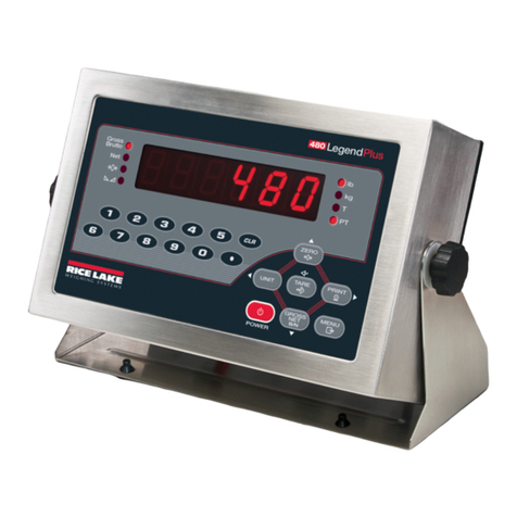
Rice Lake 480 Legend Series User manual

Rice Lake

Rice Lake 480 Legend Series User manual

Rice Lake 380 Synergy User manual

Rice Lake

Rice Lake 380 Synergy User manual

Rice Lake IQ plus 390-DC User manual

Rice Lake

Rice Lake IQ plus 390-DC User manual

Rice Lake 480 Legend Series User manual

Rice Lake

Rice Lake 480 Legend Series User manual

Rice Lake 520 User manual

Rice Lake

Rice Lake 520 User manual

Rice Lake IQ plus 390-DC Parts list manual

Rice Lake

Rice Lake IQ plus 390-DC Parts list manual

Rice Lake MSI-8000HD User manual

Rice Lake

Rice Lake MSI-8000HD User manual

Rice Lake RL1600 User manual

Rice Lake

Rice Lake RL1600 User manual

Rice Lake Counterpart CP-10 User manual

Rice Lake

Rice Lake Counterpart CP-10 User manual

Rice Lake IQ plus 210 User manual

Rice Lake

Rice Lake IQ plus 210 User manual

Rice Lake iRite 920i User manual

Rice Lake

Rice Lake iRite 920i User manual

Rice Lake FlexWeigh System 101 User manual

Rice Lake

Rice Lake FlexWeigh System 101 User manual

Rice Lake CLS-M2 User manual

Rice Lake

Rice Lake CLS-M2 User manual

Rice Lake RL9000 Series User manual

Rice Lake

Rice Lake RL9000 Series User manual

Rice Lake 320IS Plus User manual

Rice Lake

Rice Lake 320IS Plus User manual

Rice Lake 590 AG User manual

Rice Lake

Rice Lake 590 AG User manual

Rice Lake MSI-3460 Challenger 3 User manual

Rice Lake

Rice Lake MSI-3460 Challenger 3 User manual

Popular Accessories manuals by other brands

Quincy lab 140AE-1 operating manual

Quincy lab

Quincy lab 140AE-1 operating manual

HomePro ZIR000 user manual

HomePro

HomePro ZIR000 user manual

DOL 20SCR Technical user guide

DOL

DOL 20SCR Technical user guide

RAB Smart Task installation manual

RAB

RAB Smart Task installation manual

Kemppi KMS 300 quick guide

Kemppi

Kemppi KMS 300 quick guide

Stearns 57,500 Series Installation and service instructions

Stearns

Stearns 57,500 Series Installation and service instructions

iGuzzini TWILIGHT COPENAGHEN manual

iGuzzini

iGuzzini TWILIGHT COPENAGHEN manual

Adelaide Annexe & Canvas Avan Deluxe installation guide

Adelaide Annexe & Canvas

Adelaide Annexe & Canvas Avan Deluxe installation guide

OHAUS 5000 instruction manual

OHAUS

OHAUS 5000 instruction manual

HOME8 WLS1300 quick start guide

HOME8

HOME8 WLS1300 quick start guide

MAXBOTIX MaxSonar quick start guide

MAXBOTIX

MAXBOTIX MaxSonar quick start guide

ioSmart iSmart56 Installation and user guide

ioSmart

ioSmart iSmart56 Installation and user guide

Focusrite Scarlett 18i8 user guide

Focusrite

Focusrite Scarlett 18i8 user guide

Velleman ED38105 user manual

Velleman

Velleman ED38105 user manual

JumpSport SkyBounce user manual

JumpSport

JumpSport SkyBounce user manual

Prima-Temp PRIYA Instructions for use

Prima-Temp

Prima-Temp PRIYA Instructions for use

Tefcold BC85I-BC85I W user manual

Tefcold

Tefcold BC85I-BC85I W user manual

Vaisala WMS302 user guide

Vaisala

Vaisala WMS302 user guide

manuals.online logo
manuals.online logoBrands
  • About & Mission
  • Contact us
  • Privacy Policy
  • Terms and Conditions

Copyright 2025 Manuals.Online. All Rights Reserved.