Gavita Pro RS 2400e LED User manual

1
Pro line
1 Introduction
Thank you for purchasing the Gavita®Pro RS 2400e LED. This manual describes the mounting, installation, and use of the
product. Mounting and installing of the LED fixture may only be performed by certified service personnel. Please read and
understand this manual completely before using the product. Only use the product as specified in this manual.
1.1 Used Symbols
Warning! A warning indicates severe damage to the user and/or product may occur when a procedure is not carried
out as described.
Caution! A caution sign indicates problems may occur if a procedure is not carried out as described. It may also serve
as a reminder to the user.
Note: A note gives additional information, e.g. for a procedure.
This symbol is an internationally recognized symbol used to designate recyclable materials.
This symbol is an authorized use mark employed on electronic products manufactured or sold in the United States,
which indicates that the electromagnetic emissions from the device have been measured to be under the limits
published by the Federal Communications Commission. The FCC logo is a mark that declares that the equipment is
authorized to market and operate under the FCC’s SDOC procedure.
This symbol shows that a product has been independently tested and certified to meet recognized standards for safety.
The symbol on the material, accessories or packaging indicates that this product may not be discarded as household
waste. By properly disposing the equipment, you will be helping to prevent possible risks to the environment and public
health, which might otherwise be caused by improper handling of the discarded equipment. Recycling of materials
contributes to the conservation of natural resources. Therefore, please do not dispose of old electronics and electrical
appliances via household waste.
This symbol indicates the minimum distance (B) between the LED fixture (A) and the lit surface.
2 Product description
The Gavita®Pro RS 2400e LED is an electronic horticultural LED fixture. It drives eight LED rails. The Gavita®Pro RS 2400e
LED is intended to be used in greenhouses or in climate rooms. In this manual, the Gavita®Pro RS 2400e LED will be referred
to as: “the LED fixture”.
Photobiological Safety
Caution! Possibly hazardous optical radiation emitted from this product.
Attension! Rayonnement optique potentiellement dangereux émis par ce produit.
Photobiological safety assessment: Risk Group 1
Évaluation de la sécurité photobiologique: Groupe de risque 1
Gavita®Pro RS 2400e LED
A
B

2
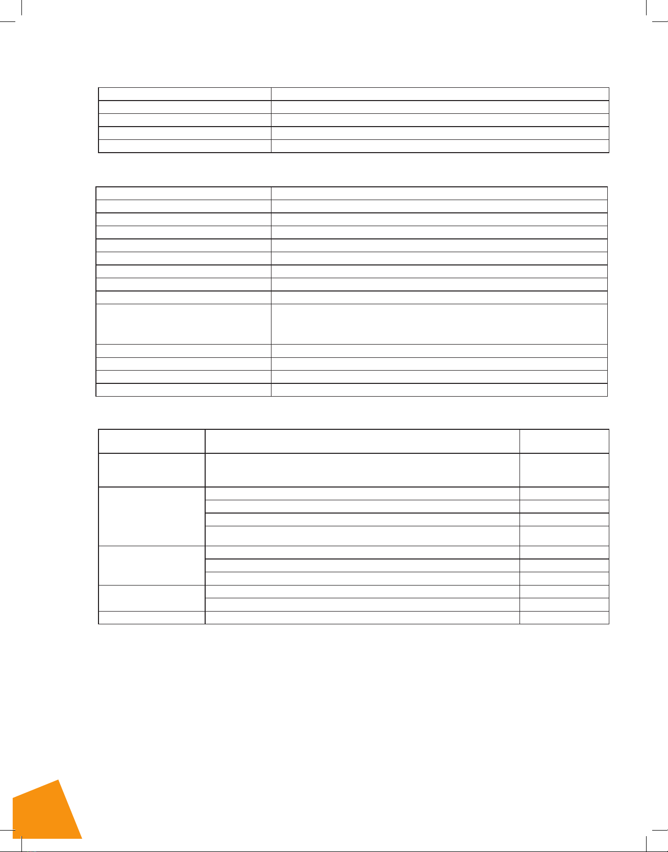
3 Product information and specifications
3.1 General product information
Product name Gavita®Pro RS 2400e LED 120-277 V
Manufacturer Hawthorne Gardening Company
Part number HGC906052
UPC 849969000351
Plug type (sold separately) NEMA 5-15P / NEMA 6-15P / Open end cable
3.2 Technical specifications
Product name Gavita®Pro RS 2400e LED 120-277 V
Input voltage +/- 10% 120-277 V
Input wattage +/- 7% 800 W
Input current at 100% 6.7 A - 2.89 A
Power factor >0.95
Product weight 36.2 lb / 16.4 kg
Dimensions (LxWxH) 43.25 x 44.8 x 3.3 in / 109.9 x 113.8 x 8.4 cm
Operating temperature 0-50° C
Frequency 50/60 Hz
Certification standards Conforms to ANSI/UL STD 1598.
Certified to CSA STD C22.2 No. 250.0.
Conforms to ANSI/CAN/UL STD 8800.
Power inlet Wieland RST 16i5 connector
External dim: Gavita Master controller analog protocol (0-11.5V)
External control signal: RJ connector (8P6C)
Environment This product is suitable for indoor wet environments
3.3 Compatible products and accessories (sold separately)
Product Product name Gavita®part number
Controllers
Unit will function
with EL3
Gavita™EL3 Master controller HGC906174
Power cords
Gavita™8 ft Power Cord 120 Volt for Gavita®LED HGC906147
Gavita™8 ft Power Cord 208-240 Volt for Gavita®LED HGC906148
Gavita™8 ft Power Cord 277-400 Volt for Gavita®LED HGC906458
Gavita™8 ft Power Cord 277 Volt Twist Lock Plug for LED HGC906182
Interconnect cables
Gavita™e-Series LED Adapter Interconnect Cable 2.5ft RJ45 to RJ45 HGC906710
Gavita™e-Series LED Adapter Interconnect Cable 10ft RJ45 to RJ45 HGC906711
3 way RJ45 cable splitter HGC906721
Light hangers Wire Hangers MS5063
Gavita®Rail System Hanging Bracket HGC906743
Power Accessories Gavita®Daisy Chain T-Splitter HGC906708
3.4 Environment
The product is intended to be used in greenhouses and climate rooms. The product is suitable for indoor wet environments.
This product may not be used outdoors. This luminaire is suitable for operation in an ambient not exceeding 50°C. This should
be the maximum sustained temperature of the installed environment (ambient temperature) that will ensure safe operation of
the lighting equipment. To prevent sustained temperatures above a 50°C ambient a mechanical ventilation or cooling system is
required to maintain the temperature within the growing space at or below 50°C when the luminaire is in operation.
Legal
This equipment has been tested and found to comply with the limits for a Class A digital device, pursuant to part 15 of the
FCC Rules. These limits are designed to provide reasonable protection against harmful interference when the equipment is
operated in a commercial environment. This equipment generates, uses, and can radiate radio frequency energy and, if not
installed and used in accordance with the instruction manual, may cause harmful interference to radio communications.

3
4 Safety recommendations and warnings
Warning! Carefully read the warnings below before using or working with the product!
• Always adhere to the local rules and regulations when installing or using the LED fixture.
• Do not open or disassemble the LED fixture, it contains no serviceable parts inside. Opening or modifying the LED fixture
can be dangerous and will void the warranty.
• This product may cause interference to radio equipment and should not be installed near maritime safety communications
equipment or other critical navigation or communication equipment operating between 0.45 - 30 MHz.
• Do not use the LED fixture when either the LED fixture or its power cord are damaged. Replace the power cord only with
original certified cords.
• Modifications to the cords can lead to unwanted electromagnetic effects, which makes the product not comply with legal
requirements.
• Do not expose the LED fixture to:
- (ambient) temperatures outside the specified range;
- dust and contamination;
- direct sunlight during use or other heat source that could heat up the driver.
• Always disconnect the LED fixture from mains before performing any maintenance.
• Always allow for a cool down period of at least 30 minutes before touching the LED rails. Touching the LED rails when the
fixture is lit or immediately afterwards can result in severe burns!
• Do not use the LED fixture near flammable, explosive or reactive substances. Do not use sulfur vaporizers or water misters.
• The installation and use of the LED fixture is the responsibility of the end user. Incorrect use or installation can lead to
failure and damage to the LED fixture. Damage to the LED fixture and electronic circuitry as a result of incorrect installation
and use voids the warranty.
5 Contents (1)
A. Gavita®Pro RS 2400e LED
1. LED drivers
2. LED rails
3. Mounting points
B. Wire Hangers (2x)
(Power cord sold separately).
6 Controls, connections and
indications (2)
A. Wieland RST 16i5 male connector
B. Communication IN Port
C. Communication OUT Port
1(;7$66<
47<
3523(57<2)
6XQOLJKW6XSSO\,QF
),1,6+
(1*$335
5(9
'21276&$/(
'5$:,1*
3$5712
%
6,=(
'(6&5,37,21
1$0(
'$7(
&+(&.('
'5$:1
0$7(5,$/
81/(6627+(5:,6(63(&,),('
',0(16,216$5(,1,1&+(6
72/(5$1&(6
)5$&7,21$/
?7+
$1*8/$5%(1'
7:23/$&('(&,0$/
7+5((3/$&('(&,0$/
$33/,&$7,21
3$5(1786('21
35235,(7$5<$1'&21),'(17,$/
7+(,1)250$7,21&217$,1(',17+,6
'5$:,1*,67+(62/(3523(57<2)
681/,*+76833/<,1&$1<
5(352'8&7,21,13$5725$6$
:+2/(:,7+2877+(:5,77(1
3(50,66,212)681/,*+76833/<,1&
,6352+,%,7('
6+((72)
5(9,6,21+,6725<
$33529('
'(6&5,37,21
'$7(
5(9
'5$:,1*127(6
$
+
*
)
(
'
&
%
)
'
+
%
*
(
&
$
A
1(;7$66<
47<
3523(57<2)
6XQOLJKW6XSSO\,QF
),1,6+
(1*$335
5(9
'21276&$/(
'5$:,1*
3$5712
%
6,=(
'(6&5,37,21
1$0(
'$7(
&+(&.('
'5$:1
0$7(5,$/
81/(6627+(5:,6(63(&,),('
',0(16,216$5(,1,1&+(6
72/(5$1&(6
)5$&7,21$/
?7+
$1*8/$5%(1'
7:23/$&('(&,0$/
7+5((3/$&('(&,0$/
$33/,&$7,21
3$5(1786('21
35235,(7$5<$1'&21),'(17,$/
7+(,1)250$7,21&217$,1(',17+,6
'5$:,1*,67+(62/(3523(57<2)
681/,*+76833/<,1&$1<
5(352'8&7,21,13$5725$6$
:+2/(:,7+2877+(:5,77(1
3(50,66,212)681/,*+76833/<,1&
,6352+,%,7('
6+((72)
5(9,6,21+,6725<
$33529('
'(6&5,37,21
'$7(
5(9
'5$:,1*127(6
$
+
*
)
(
'
&
%
)
'
+
%
*
(
&
$
B
C
A2
A
B
A1
A3
1.
2.
Operation of this equipment in a residential area is likely to cause harmful interference in which case the user will be required to correct
the interference at his own expense.
Caution! Changes or modifications not expressly approved by the party responsible for FCC compliance could void the user's authority
to operate the equipment. Conforms to ANSI/UL 1598 and Certified to CSA C22.2 No. 250.0 and ANSI/CAN/UL 8800.

4
7 Installation
Caution! PROPRIETARY WIRING SYSTEM. Use Hawthorne cord set model HGC906147, HGC906148, or HGC906458 only for
connection from the luminaire power inlet to a standard junction box for power connection.
Attention! SYSTÈME DE CÂBLAGE PROPRIÉTAIRE. Utilisez le jeu de cordons Hawthorne modèle HGC906147, HGC906148
ou HGC906458 uniquement pour la connexion de l'entrée d'alimentation du luminaire à une boîte de jonction standard pour la
connexion électrique.
Warning! Mounting and installing of the LED fixture may only be executed by certified service personnel, in accordance with
the applicable local laws and regulations.
Warning! The installer is responsible for correct and safe installation.
Warning! Ensure the local cabling can support the voltage and current requirements of the LED fixture.
Warning! Avoid coiled cords and keep mains leads separated. This prevents electromagnetic interference.
Warning! Do not connect or disconnect the LED fixture under load.
7.1 Installation preparations
Warning! Mount the system to something that can hold the weight of the LED fixture.
•Switch off mains power.
•Install the Gavita Rail System Hanging Bracket (fig. 3) (sold separately). Or install the Wire Hangers (fig. 1B).
•Make sure power cords:
1) Are not concealed or extended through a wall, floor, ceiling, or other parts of the building structures
2) Are not located above a suspended ceiling or dropped ceiling.
3) Are not permanently affixed to the building structure.
4) Are routed so that they are not subject to strain and are protected from physical damage.
5) Are visible over their entire length.
6) Are used within their rated ampacity as determined for the maximum temperature of the installed environment
specified in the instructions.
Installing the LED fixture
The Gavita Pro RS 2400e offers multiple mounting points for increased versatility. When using the Gavita Rail System Hanging
Bracket (fig. 3) (sold separately), use the innermost mounting point (fig. 4A). If utilizing Sungrips ratchet style rope hangers,
included mounting hardware, or hanging from a single point; utilize the outermost mounting point (fig. 4B). Note: when
mounting from a single point, utilizing the outermost mounting points will allow the fixture to completely unfold and remain
flat.
•Hang the LED fixture to the mounting system.
•Distribute weight evenly and ensure the LED fixture is the appropriate distance above crop height (fig. 5).
•If using the LED fixture as a stand-alone device, continue to Section 7.4.
•If using the LED fixture with a Master Controller, continue to Section 7.3.
To install additional LED fixtures, repeat sections 7.1 and 7.2 for each device.
3. 4. 5.
640W
60 cm
23 in
750W
0.75 m -
30 in
800W
A
A
B
B
A
A
B
B

5
7.2 Connecting up to 512 LED fixtures
• Remove the dummy plug from the input port on the first LED.
Note: Keep the dummy in a safe place! The dummy is necessary to operate the LED fixture in standalone mode.
• Use the controller cable (RJ45 to RJ45) (fig. 6A) to connect the controller input port (fig. 6B) on the first LED.
• Remove the dummy from the input port on the second LED.
• Use interconnect cable (RJ45-RJ45) to connect the output port (fig. 6C) of the first LED fixture to the input port of the
second LED fixture.
• Repeat these steps to connect up to 512 LED fixtures.
Warning! Ensure the power cord and the controller cables do not touch any of the LED rails.
A
BIN OUT POWER
C
6.

6
7.3 Connecting the LED fixture to the mains
Warning! Make sure mains power is switched off.
Warning! Ensure the cord is not coiled and does not touch any hot surfaces.
Warning! Connect the cables according to local rules, safety regulations and electrical code.
Warning! Ensure external switching gear can cope with the inrush current of the LED fixture (see section 3.2). Always use a
double pole contactor suitable for switching a capacitive load. Never use household timers to switch the LED fixture!
• Connect the Wieland RST 16i5 female connector on the power cable to the Wieland RST16i5 male connector on the LED
fixture (fig. 7).
• Connect the power cable to the mains (fig. 8). Ensure use of the appropriate power cord for the NEMA socket. Please
reference section 3.3 for compatible power cords.
Cable description 2400e LED 120V / 277V, and 240V:
Wire 120 V, 277 V 240 V
White Neutral (N) Line (L1)
Black Phase (L) Line (L2 )
Green Ground ( ) Ground ( )
• Switch on mains power.
Warning! Do not connect or disconnect the power cable to the LED fixture while under load.
. .

7
8 Inspection, maintenance and repair
Warning! Disconnect the LED fixture from mains before performing any maintenance or repairs.
Warning! Do not connect or disconnect the LED fixture under load.
Warning! Do not open or disassemble the LED fixture, it contains no serviceable parts inside. Opening the LED fixture can
be dangerous and will void the warranty.
Warning! Always allow for a cool down period of at least 30 minutes before touching the LED rails.
Caution! Do not clean the LED fixture with detergents, abrasives, or ANY other POTENTIALLY aggressive substances.
• Regularly check the LED fixture for dust or dirt buildup. Clean if necessary with 70% Isopropyl Alcohol and apply with a
non-abrasive cloth. Contamination may cause overheating and decreased performance. Clean the outside of the LED fixture
using a dry or damp cloth.
• Regularly check the cables of the LED fixture to ensure they are undamaged.
8.1 How to disconnect the Wieland RST16i5 plug
Warning! Do no connect or disconnect the Wieland RST16i5 plug while the fixture is in operation.
• Switch off mains power.
• Turn the ring on the Wieland RST16i5 female connector counterclockwise and
pull the Wieland RST16i5 female connection from the LED fixture (fig. 9).
9 Storage and disposal
• Store the LED fixture in a dry and clean environment, with an ambient
temperature of -4~122° F / -20~50° C.
• The product must not be discarded as unsorted municipal waste, but must be
collected separately for the purpose of treatment, recovery, and environmentally
sound disposal.
10 LIMITED WARRANTY:
When purchased from an authorized Hawthorne dealer, this product is covered by a
LIMITED WARRANTY, available at hawthornegc.com/warranties. You can also obtain
the Terms of Sale and Limited Warranty by calling Hawthorne toll-free
at: 1-888-478-6544 or writing Hawthorne at: Hawthorne Hydroponics LLC, 3204 NW 38th Circle, Vancouver, WA 98660,
Attn: Customer Service.
1
2
9.

220404aSD
Manufactured for Hawthorne Hydroponics LLC,
a subsidiary of The Hawthorne Gardening Company
3204 NW 38th Circle, Vancouver, WA 98660
HawthorneGC.com | Canada: HawthorneGC.ca | P +1-360-883-8846 | E info@gavita.com
®/™ used under license by Hawthorne Canada Limited.
©2022. World rights reserved.
LB19144 Instruction Manual - Gavita Pro 2400e LED

1
Pro line
1 Introduction
Nous vous remercions de votre achat de Gavita® Pro RS 2400e LED. Le manuel suivant concerne le montage, l’installation et l’utilisation
du produit. Le montage et l’installation du dispositif à DEL ne peuvent être effectués que par du personnel de service certifié. Veuillez vous
familiariser avec ce manuel et vous assurer de le comprendre avant d’utiliser le produit. N’utiliser le produit que de la manière spécifiée dans
le manuel.
1.1 Symboles utilisés
Avertissement! Un avertissement indique qu’un danger important pour l’utilisateur ou des dommages importants au produit peuvent
survenir lorsqu’une procédure n’est pas effectuée comme indiqué.
Mise en garde! Un symbole de mise en garde signifie que des problèmes peuvent survenir lorsqu’une procédure n’est pas effectuée
comme indiqué. Il sert également de rappel à l’utilisateur.
Remarque : Une remarque offre des renseignements supplémentaires, par exemple pour une procédure.
Ce symbole est reconnu internationalement et il est utilisé pour désigner des matériaux recyclables.
Ce symbole autorisé est utilisé sur les produits électroniques fabriqués ou vendus aux États-Unis, indiquant que les émissions
électromagnétiques du dispositif ont été mesurées et se situent sous les limites publiées par la Federal Communications Commission
(Commission fédérale des communications). Le logo de la FCC est un symbole qui indique que l’équipement est autorisé sur le
marché et fonctionne selon la procédure SDOC de la FCC.
Ce symbole signifie qu'un produit a été testé et certifié indépendamment pour satisfaire aux normes de sécurité.
Le symbole apparaissant sur les matériaux, les accessoires ou les emballages indique que ce produit ne peut être jeté comme ordure
ménagère. En disposant adéquatement de l'équipement, vous contribuerez à empêcher des risques possibles à l'environnement
et à la santé publique, qui autrement auraient été causés par une manipulation inadéquate de l'équipement jeté. Le recyclage des
matériaux contribue à la conservation des ressources naturelles. Veuillez donc éviter de jeter des dispositifs électroniques et des
équipements ménagers désuets avec les ordures ménagères.
Ce symbole indique la distance minimum (B) entre le dispositif à DEL (A) et la surface éclairée.
2 Description du produit
Le Gavita® Pro RS 2400e LED est un dispositif électronique d'horticulture à DEL. Le dispositif comporte huit traverses à DEL. Le Gavita® Pro
RS 2400e LED est recommandé pour une utilisation en serre ou dans des pièces tempérées. Dans ce manuel le Gavita® Pro RS 2400e LED
sera dénommé : « le dispositif à DEL ».
Sécurité photobiologique
Caution! Possibly hazardous optical radiation emitted from this product.
Mise en garde! Rayonnement optique potentiellement dangereux émis par ce produit.
Photobiological safety assessment: Risk Group 1
Évaluation de la sécurité photobiologique : Groupe de risque 1
Gavita®Pro RS 2400e LED
A
B
2
3 Informations et caractéristiques du produit
3.1 Informations générales sur le produit
Nom du produit Gavita®Pro RS 2400e LED 120-277 V
Fabricant Hawthorne Gardening Company
Numéro de pièce HGC906052
CUP 849969000351
Type de fiche (vendue séparément) NEMA 5-15P/NEMA 6-15P/câble à extrémité ouverte
3.2 Caractéristiques techniques
Nom du produit Gavita®Pro RS 2400e LED 120-277 V
Tension d'entrée +/- 10 % 120-277 V
Puissance électrique d'entrée +/- 7 % 800 W
Courant d'entrée à 100 % 6,7 A à 2,89 A
Facteur de puissance >0,95
Poids du produit 16,4 kg/36,2 lb
Dimensions (L. X l. x H.) 109,9 x 113,8 x 8,4 cm/43,25 x 44,8 x 3,3 po
Température d'exploitation 0 à 50 °C
Fréquence : 50/60 Hz
Normes de certification
Satisfait à ANSI/UL STD 1598.
Certifié selon le CSA STD C22.2 No 250.0.
Satisfait à ANSI/CAN/UL STD 8800.
Entrée d'alimentation Raccord Wieland RST 16i5
External dim : Protocole analogique du contrôleur central Gravita (0 à 11,5 V)
Signal de commande externe : Raccord RJ (8P6C)
Environnement Ce produit convient aux environnements intérieurs mouillés
3.3 Produits et accessoires compatibles (vendus séparément)
Produit Nom du produit Numéro de pièce
Gavita®
Contrôleurs
Le dispositif fonctionne
avec EL3
Contrôleur central Gavita™ EL3 HGC906174
Cordons d'alimentation
Cordon d'alimentation Gavita™ de 2,5 m (8 pi) et de 120 volts pour Gavita® LED HGC906147
Cordon d'alimentation Gavita™ de 2,5 m (8 pi) et de 208 à 240 volts pour Gavita® LED HGC906148
Cordon d'alimentation Gavita™ de 2,5 m (8 pi) et de 277 à 400 volts pour Gavita® LED HGC906458
Cordon d'alimentation Gavita™ de 2,5 m (8 pi) et de 277 volts avec
fiche verrouillable pour Gavita® LED HGC906182
Câbles de liaison
Câble de liaison avec adaptateur Gavita™ e-Series LED de 0,7 m (2,5 pi) RJ45 à RJ45 HGC906710
Câble de liaison avec adaptateur Gavita™ e-Series LED de 3 m (10 pi) RJ45 à RJ45 HGC906711
Séparateur de câble à 3 voies HGC906721
Supports d'éclairage Câbles de support MS5063
Ferrure de suspension pour système de traverses Gavita®HGC906743
Accessoires d'alimentation Séparateur en T avec chaînette en série Gavita®HGC906708
3.4 Environnement
Il est recommandé d'utiliser le produit en serre ou dans des pièces tempérées. Le produit convient aux environnements intérieurs mouillés.
N'utilisez pas ce produit à l'extérieur. Ce dispositif d'éclairage convient à un fonctionnement dans une température ambiante ne dépassant
pas 50 °C. Il s'agit de la température maximale maintenue de l'environnement d'installation (température ambiante) qui assurera un
fonctionnement sécuritaire de l'équipement d'éclairage. Un système de ventilation mécanique ou un système de refroidissement est requis
pour maintenir une température ambiante maximale de 50 °C dans l'espace de croissance lorsque l'éclairage fonctionne.
Mention légale
Cet équipement a été testé et il satisfait aux normes d'un dispositif numérique de catégorie A, conformément à la partie 15 des règlements de
la FCC. Ces normes sont établies dans le but d'offrir une protection raisonnable contre le brouillage nuisible lorsque l'équipement fonctionne
dans un environnement commercial. L'équipement génère, utilise et peut émettre des radiofréquences et s'il n'est pas installé conformément
au manuel d'instruction, il peut causer un brouillage nuisible aux radiocommunications.

3
4 Recommandations en matière de sécurité et avertissements
Avertissement! Veuillez lire attentivement les avertissements ci-dessous avant de travailler avec le produit ou de l'utiliser!
• Conformez-vous en tout temps aux règlements locaux lors de l'installation ou de l'utilisation du dispositif à DEL.
• N'ouvrez pas ou ne démontez pas le dispositif à DEL; il ne contient aucune pièce réparable à l'intérieur. Ouvrir ou modifier le dispositif à DEL peut
s'avérer dangereux et annulera la garantie.
• Ce produit peut causer des interférences avec l'équipement radio et il ne doit pas être installé près d'équipement de communication de sécurité
maritime ni d'autres équipements de navigation ou de communication esentiels fonctionnant entre 0,45 et 30 MHz.
• N'utilisez pas le dispositif à DEL lorsque ce dernier est endommagé ou que son cordon d'alimentation est endommagé. Remplacez le cordon
d'alimentation uniquement par des cordons originaux certifiés.
• Des modifications aux cordons peuvent entraîner des effets électromagnétiques non désirés, rendant le produit non conforme aux exigences légales.
• N'exposez pas le dispositif à DEL :
- aux températures (ambiantes) au-delà de la plage spécifiée;
- à la poussière et aux contaminants;
- à la lumière directe du soleil ou à toute autre source de chaleur pendant l'utilisation, car cela pourrait faire chauffer le moteur.
• Débranchez toujours le dispositif à DEL du conducteur principal avant d'effectuer tout entretien.
• Prévoyez toujours une période de refroidissement d'au moins 30 minutes avant de toucher les traverses du dispositif à DEL. Toucher les traverses
lorsque le dispositif est allumé ou immédiatement après l'avoir éteint peut entraîner des brûlures sévères!
• N'utilisez pas le dispositif à DEL près de substances inflammables, explosives ou réactives.
N'utilisez pas de pulvérisateurs de soufre ni de brumisateurs
• L'installation et l'utilisation du dispositif à DEL sont la responsabilité de l'utilisateur final. Une mauvaise utilisation ou installation peut entraîner une
défaillance et endommager le dispositif à DEL. Des dommages au dispositif à DEL et aux circuits électroniques résultant d'une mauvaise installation
ou utilisation annulent la garantie.
5 Contenu (1)
A. Gavita®Pro RS 2400e LED
1. Moteurs DEL
2. Traverses DEL
3. Points de montage
B. Supports à câbles (2x)
(Cordon d'alimentation vendu séparément.)
6 Contrôles, raccords et indications (2)
A. Raccord mâle Wieland RST 16i5
B. Port D'ENTRÉE pour communication
C. Port de SORTIE pour communication
1(;7$66<
47<
3523(57<2)
6XQOLJKW6XSSO\,QF
),1,6+
(1*$335
5(9
'21276&$/(
'5$:,1*
3$5712
%
6,=(
'(6&5,37,21
1$0(
'$7(
&+(&.('
'5$:1
0$7(5,$/
81/(6627+(5:,6(63(&,),('
',0(16,216$5(,1,1&+(6
72/(5$1&(6
)5$&7,21$/
?7+
$1*8/$5%(1'
7:23/$&('(&,0$/
7+5((3/$&('(&,0$/
$33/,&$7,21
3$5(1786('21
35235,(7$5<$1'&21),'(17,$/
7+(,1)250$7,21&217$,1(',17+,6
'5$:,1*,67+(62/(3523(57<2)
681/,*+76833/<,1&$1<
5(352'8&7,21,13$5725$6$
:+2/(:,7+2877+(:5,77(1
3(50,66,212)681/,*+76833/<,1&
,6352+,%,7('
6+((72)
5(9,6,21+,6725<
$33529('
'(6&5,37,21
'$7(
5(9
'5$:,1*127(6
$
+
*
)
(
'
&
%
)
'
+
%
*
(
&
$
A
1(;7$66<
47<
3523(57<2)
6XQOLJKW6XSSO\,QF
),1,6+
(1*$335
5(9
'21276&$/(
'5$:,1*
3$5712
%
6,=(
'(6&5,37,21
1$0(
'$7(
&+(&.('
'5$:1
0$7(5,$/
81/(6627+(5:,6(63(&,),('
',0(16,216$5(,1,1&+(6
72/(5$1&(6
)5$&7,21$/
?7+
$1*8/$5%(1'
7:23/$&('(&,0$/
7+5((3/$&('(&,0$/
$33/,&$7,21
3$5(1786('21
35235,(7$5<$1'&21),'(17,$/
7+(,1)250$7,21&217$,1(',17+,6
'5$:,1*,67+(62/(3523(57<2)
681/,*+76833/<,1&$1<
5(352'8&7,21,13$5725$6$
:+2/(:,7+2877+(:5,77(1
3(50,66,212)681/,*+76833/<,1&
,6352+,%,7('
6+((72)
5(9,6,21+,6725<
$33529('
'(6&5,37,21
'$7(
5(9
'5$:,1*127(6
$
+
*
)
(
'
&
%
)
'
+
%
*
(
&
$
B
C
A2
A
B
A1
A3
Le fonctionnement de cet équipement dans une zone résidentielle peut causer un brouillage nuisible auquel cas l’utilisateur devra remédier au brouillage à
ses frais.
Mise en garde! Toute modification non expressément approuvée par la partie responsable à la conformité aux normes de la FCC annule l'autorité de
l'utilisateur à se servir de l'équipement. Satisfait à ANSI/UL 1598 et certifié CSA C22.2 No 250.0 et ANSI/CAN/UL 8800.
1.
2.

4
7 Installation
Caution! PROPRIETARY WIRING SYSTEM. Use Hawthorne cord set model HGC906147, HGC906148, or HGC906458 only for connection from
the luminaire power inlet to a standard junction box for power connection.
Mise en garde! SYSTÈME DE CÂBLAGE EXCLUSIF. Utilisez le jeu de cordons Hawthorne modèle HGC906147, HGC906148 ou
HGC906458 uniquement pour la connexion de l'entrée d'alimentation du dispositif d'éclairage à une boîte de jonction standard pour la
connexion électrique.
Avertissement! Le montage et l'installation du dispositif à DEL ne peuvent être effectués que par du personnel de service certifié selon les
règlements locaux applicables.
Avertissement! L'installateur est responsable d'une installation adéquate et sécuritaire.
Avertissement! Assurez-vous que le câblage local peut soutenir les exigences de tension de courant du dispositif à DEL.
Avertissement! Évitez que les cordons ne s'enroulent et gardez les câbles conducteurs principaux séparés. Cela permet de prévenir les
interférences électromagnétiques.
Avertissement! Ne pas brancher ou débrancher le dispositif à DEL lorsqu'il est sous tension.
7.1 Préparations pour l'installation
Avertissement! Fixez le système à une structure pouvant soutenir le poids du dispositif à DEL.
• Éteindre l'alimentation principale.
• Installez la ferrure de suspension pour système de traverses Gavita® (fig. 3) (vendue séparément).
Ou installez les supports à câbles (fig. 1B).
• Assurez-vous que les cordons d'alimentation :
1) ne sont pas dissimulés ou déployés dans un mur, un plancher, un plafond ou dans d'autres parties de la structure du bâtiment.
2) ne se situent pas au-dessus d'un plafond suspendu ou d'un sous-plafond.
3) ne sont pas fixés à la structure du bâtiment de façon permanente.
4) sont dirigés de façon à ne pas être soumis à une tension et qu'ils sont protégés contre les dommages physiques.
5) sont visibles dans leur intégralité.
6) sont utilisés selon l'intensité admissible nominale qui est déterminée en fonction de la température maximale
de l'environnement où ils sont installés, spécifiée dans les directives.
Installation du dispositif à DEL
Le Gavita Pro RS 2400e offre plusieurs points de montage pour une polyvalence accrue. Lorsque vous utilisez la ferrure de suspension
pour système de traverses Gavita (fig. 3) (vendue séparément), utilisez les points de montage les plus centraux (fig. 4A). Si vous utilisez des
supports à cordons à cliquet Sun Grip, quincaillerie de montage comprise, ou si vous suspendez à partir d'un seul point; utilisez les points
de montage les plus externes (fig. 4B). Remarque : Lors du montage à partir d'un point unique, l'utilisation des points de montage les plus
externes permettra au dispositif d'être étiré entièrement tout en demeurant à plat.
• Fixez le dispositif à DEL au système de montage.
• Distribuez le poids uniformément et assurez-vous que le dispositif à DEL est situé à une distance adéquate au-dessus des cultures (fig. 5).
• Si le dispositif à DEL est utilisé comme appareil autonome, continuez à la section 7.4.
• Si le dispositif à DEL est utilisé avec un contrôleur central, continuez à la section 7.3.
Pour installer des dispositifs à DEL supplémentaires, répétez les sections 7.1 et 7.2 pour chaque appareil.
640W
60 cm
23 in
750W
0.75 m -
30 in
800W
A
A
B
B
A
A
B
B
3. 4. 5.

5
7.2 Brancher jusqu'à 512 dispositifs à DEL
• Retirez la fiche isolante du port d'entrée du premier dispositif à DEL.
Remarque : Placez la fiche isolante dans un endroit sûr! La fiche isolante est nécessaire au fonctionnement du dispositif à DEL en
mode autonome.
• Utilisez le câble du contrôleur (RJ45 à RJ45) (fig. 6A) pour brancher le port d'entrée du contrôleur (fig. 6B) au premier dispositif à DEL.
• Retirez la fiche isolante du port d'entrée du second dispositif à DEL.
• Utilisez le câble de liaison (RJ45 à RJ45) pour brancher le port de sortie (fig. 6C) du premier dispositif à DEL au port d'entrée du
deuxième dispositif à DEL.
• Répétez ces étapes pour brancher jusqu'à 512 dispositifs à DEL.
Avertissement! Assurez-vous que le cordon d'alimentation et que les câbles de contrôle ne touchent pas les
traverses du dispositif à DEL.
A
BENTRÉE SORTIE ALIMENTATION
C
6.

6
7.3 Branchement du dispositif à DEL au conducteur principal
Avertissement! Assurez-vous d'éteindre l'alimentation au conducteur principal.
Avertissement! Assurez-vous que le cordon n'est pas enroulé et qu'il n'est pas en contact avec des surfaces chaudes.
Avertissement! Branchez les câbles conformément aux règlements locaux, aux règlements de sécurité et au code de l'électricité.
Avertissement! Assurez-vous que l'équipement de commutation externe peut soutenir l'appel de courant du dispositif à DEL (voir section 3.2).
Utilisez en tout temps un contacteur bipolaire convenant à la commutation d'une charge capacitive. N’utilisez jamais une minuterie maison pour
commuter le dispositif à DEL!
• Branchez le raccord femelle Wieland RST 16i5 du câble d'alimentation au raccord mâle Wieland RST16i5 du dispositif à DEL (fig. 7).
• Branchez le câble d'alimentation au conducteur principal (fig. 8). S'assurer d'utiliser le câble d'alimentation adéquat pour la prise de courant
NEMA. Veuillez consulter la section 3.3 pour y trouver des renseignements concernant les câbles
d'alimentation compatibles.
Description des câbles 2400e DEL 120 V/277 V et 240 V :
Câble 120 V, 277 V 240 V
Blanc Neutre (N) Ligne (L1)
Noir Phase (L) Ligne (L2 )
Vert Fil de terre ( ) Fil de terre ( )
• Allumez l'alimentation principale.
Avertissement! Ne branchez pas ou ne débranchez pas le câble d'alimentation du dispositif à DEL lorsque ce dernier
est sous tension.
. .

7
8 Inspection, entretien et réparation
Avertissement! Débranchez le dispositif à DEL du conducteur principal avant d'effectuer tout entretien ou toute réparation.
Avertissement! Ne branchez pas ou ne débranchez pas le dispositif à DEL lorsqu'il est sous tension.
Avertissement! N'ouvrez pas ou ne démontez pas le dispositif à DEL; il ne contient aucune pièce réparable à l'intérieur. Ouvrir le dispositif
peut s'avérer dangereux et annulera la garantie.
Avertissement! Prévoyez toujours une période de refroidissement d'au moins 30 minutes avant de toucher les traverses
du dispositif à DEL.
Mise en garde! Ne nettoyez pas le dispositif à DEL avec des détergents, des substances abrasives ou TOUTE autre substance
POTENTIELLEMENT agressive.
• Contrôlez régulièrement l'accumulation de poussière et de saleté sur le dispositif à DEL. Nettoyez si nécessaire avec de l'alcool
isopropylique à 70 % et appliquez avec un linge doux. La contamination peut entraîner une surchauffe du dispositif, réduisant ainsi son
rendement. Nettoyez l'extérieur du dispositif à DEL à l'aide d'un chiffon sec ou humide.
• Vérifiez régulièrement que les câbles liés au dispositif à DEL ne sont pas endommagés.
8.1 Comment débrancher la fiche Wieland RST16i5
Avertissement! Ne branchez pas ou ne débranchez pas la fiche Wieland RST16i5 alors que
le dispositif fonctionne.
• Éteindre l'alimentation principale.
• Tournez l'anneau du connecteur femelle Wieland RST16i5 dans le sens inverse des
aiguilles d'une montre et tirez le raccord femelle du Wieland RST16i5 du dispositif à DEL
(fig. 9).
9 Entreposage et élimination
• Entreposez le dispositif à DEL dans un environnement propre et sec avec une température
ambiante de -20 à 50 °C/-4 à 122 °F.
• Le produit ne doit pas être jeté comme déchet municipal non trié, mais il doit être ramassé
séparément pour une élimination incluant le traitement, la récupération et l'élimination
écologique.
10 GARANTIE LIMITÉE :
Lorsqu'il est acheté auprès d'un distributeur Hawthorne, ce produit est couvert par une GARANTIE LIMITÉE, offerte sur hawthornegc.com/
warranties. Vous pouvez également obtenir les renseignements concernant les conditions de vente et la garantie limitée en téléphonant sans
frais au : 1 888 478-6544 ou en écrivant à : Hawthorne Hydroponics LLC, 3204 NW 38th Circle, Vancouver, WA 98660, Att. : Service à la clientèle.
1
2
9.

220404aSD
Fabriqué pour Hawthorne Hydroponics LLC,
une filiale de The Hawthorne Gardening Company
3204 NW 38th Circle, Vancouver, WA 98660
HawthorneGC.com | Canada: HawthorneGC.ca | Tél. +1-360-883-8846 | Courriel info@gavita.com
®/™ utilisee licence par Hawthorne Canada Limited.
©2022. Tous droits mondiaux réservés.
Manuel d'instruction LB19144l - Gavita Pro 2400e LED

THIS PAGE DOES NOT
PRINT AND ONLY FOR
TITLE BLOCK
Hawthorne Project Number:
OBF Project #:
Hawthorne Project Lead:
OBF Job #:
Wave:UPC #:
UPC SIZE: UPC BW:
SKU #:
Component #:
Hawthorne Production
8
Sheri Deane
HGC906052
LB19144
Nicole Downs
119235
HGC906052-01_LB19144_Gavita_RS_2400e_LED_LAUNCH_Manual-ENG-FRNCH_220404aSD.indd
HGC906052-01_LB19144_Gavita_RS_2400e_LED_LAUNCH_Manual-ENG-FRNCH_220404aSD.indd
HGC906052-01_LB19144_Gavita_RS_2400e_LED_LAUNCH_Manual-ENG-FRNCH_2200404aSD.indd
Manual/Instructions
119235 Potamus Press. Temecula, CA
04/04/22
8.5 x 11
4
Cyan
Magenta
Yellow
7
Oset per SAP
Table of contents
Languages:
Other Gavita Lighting Equipment manuals

Gavita
Gavita GAN Electronic 750 W User manual

Gavita
Gavita Pro line HortiStar 1000 DE EU User manual

Gavita
Gavita Pro Series User manual

Gavita
Gavita DigiStar 400 User manual

Gavita
Gavita CT 1930e User manual

Gavita
Gavita GAN Electronic 750 W 400 V DE EU User manual

Gavita
Gavita Pro 1000e User manual

Gavita
Gavita Proline CT 2000e User manual

Gavita
Gavita GAN Electronic 600 W 230 V EU User manual


