Gavita Pro 1000e User manual

1
Pro line
1 Introduction
Thank you for purchasing the Gavita Pro 1000e 380-400V DE EU. This manual describes the mounting and installing of the
product and also describes how to use the product. Please read and understand this manual completely before using the
product. Only use the product as specified in this manual.
1.1 Used Symbols
Warning! A warning indicates severe damage to the user and/or product may occur when a procedure is not carried
out as described.
Caution! A caution sign indicates problems may occur if a procedure is not carried out as described. It may also
serve as a reminder to the user.
Note: A note gives additional information, e.g. for a procedure.
This symbol indicates that the reflector and lamp can reach very high temperatures (>85 °Celsius). Observe a cool
down period before performing maintenance.
With this symbol Gavita declares that this product complies with European requirements.
The symbol on the material, accessories or packaging indicates that this product may not be discarded as
household waste. By disposing of the equipment in the proper way, you will be helping to prevent possible risks
to the environment and public health, which might otherwise be caused by improper handling of the discarded
equipment. Recycling of materials contributes tot the conservation of natural resources. Therefore, please do not
dispose of your old electronics and electrical appliances via household waste.
A
B
This symbol indicates the minimum distance (B) between the luminaire (A) and the lit surface.
2 Product description
The Gavita Pro 1000e 380-400V DE EU is an adjustable horticultural luminaire. The Gavita Pro 1000e 380-400V DE EU can
be used to drive a double ended 380-400V high frequency (electronic) high pressure sodium lamp.
The Gavita Pro 1000e 380-400V DE EU is an e-series product. It can be remotely switched and adjusted by a Gavita Master
controller. The controller can automatically switch the luminaire on and off during a 24 hour cycle.
The controller also offers a temperature safety feature: auto-dimming or switching off connected luminaires when the
temperature in a climate room becomes too high.
The product can also be controlled by conventional timers in combination with a contactor. Make sure the dummy RJ plug
sits in the IN port. If not, the luminaire will not operate.
In this manual, the Gavita Pro 1000e 380-400V DE EU will be referred to as: “the luminaire”.
Gavita Pro 1000e 380-400V

2
Pro line
Pro line
3 Product information and specifications
3.1 General product information
Product name Gavita Pro 1000e 380-400V DE EU
Manufacturer Gavita International BV
Version HR96 W150
EAN Code 8718692232594 8718692232617
Part number HGC906201 HGC906301
3.2 Technical specifications
Version Gavita Pro 1000e 380-400V DE EU
Product weight 3.8 kg
Dimensions (L*W*H) 56.5 x 24.5 x 19.5 cm
Temperature case < 70 °Celsius
Temperature ambient 0 - 35 °Celsius
Input voltage 380 - 400 V AC -10% / +8%
Input current typical 2.8 - 2.7 Amps
Input power typical 1050 Watt
Power factor > 0.98
Total Harmonic Distortion < 10%
Frequency 50 - 60 Hz
Certification EN 60598-1, EN 55015-2015
Insulation Class 1 - requires an earth connection
Power inlet Wieland RST20i3 connector
Inrush current ≤ 40 A, 1.8 ms
Earth leakage current ≤ 1 mA

3
Pro line
Pro line
3.3 Compatible products and accessories
Product name Gavita part number
Compatible controllers Gavita Master Controller EL1 EU Gen2 HGC990786
Gavita Master Controller EL2 EU Gen2 HGC990786
Gavita Master Controller EL1F EU Gen2 HGC990792
Gavita Master Controller EL2F EU Gen2 HGC990794
Replacement reflector Gavita HR96 DE S9021200
Gavita MD 135 DE HC S7012101
Gavita W 150 DE S7013101
Compatible lamps Gavita Pro Plus 1000 W EL DE HPS LP8011816
Compatible power cord Wieland RST20i3 0,6 m mains cable CB6873121
Compatible interconnect cable Interconnect cable RJ CB6633621
Repeater bus connection kit HGC906170
3.4 Environment
The product is intended to be used in greenhouses and climate rooms. The product can be used in damp environments. The
product may not be used in wet environments or outdoors. The lamps function optimally when the ambient temperature is
between 20 ~ 30 °C.
3.5 Legal
CE LVD approval according to: EN 60598-1: 2008 + A11: 2009.
CE EMC approval according to: EN 55015 (2013).
4 Safety recommendations and warnings
6Warning! Carefully read the warnings below before using or working with the product!
• Always adhere to the local rules and regulations when installing or using the luminaire.
• Do not open or disassemble the luminaire, it contains no servicable parts inside. Opening the luminaire can be
dangerous and will void the warranty.
• This product may cause interference to radio equipment and should not be installed near maritime safety
communications equipment or other critical navigation or communication equipment operating between 0.45 - 30
MHz.
• Do not use the luminaire when either its lamp or its power cord are damaged. Replace the power cord only with
original certified cords. Replace the lamp only with lamps specified by Gavita (see paragraph 3.3).
• The use of other lamps may damage the product and lamp and will void the warranty.
• Modifications to the cords can lead to unwanted electromagnetic effects, which makes the product not comply with
legal requirements.
• Do not expose the luminaire to:
− condensing humidity, heavy mist, fog or direct spray;
− (ambient) temperatures outside the specified range;
− dust and contamination;
− direct sunlight during use or HID light that could heat up the ballast.
• Always disconnect the luminaire from mains before performing any maintenance.
• Always allow for a cool down period of at least 30 minutes before touching the lamp or reflector. Touching the lamp or
the reflector when the lamp is lit or immediately afterwards will result in severe burns!
• Never touch the lamp with bare hands as this will cause damage to the lamp.
• Do not use the luminaire near or above flammable, explosive or reactive substances. The lamp and the reflector of the
luminaire reach temperatures of > 85 °Celsius.

4
Pro line
Pro line
• Do not use sulfur vaporizers or water misters. Sulfur and calcium deposits on your reflector will decrease its
efficiency.
• The installation and use of the luminaire is the responsibility of the end user. Incorrect use or installation can lead
to failure and damage to the luminaire. Damage to the luminaire and electronic circuitry as a result of incorrect
installation and use revokes the warrant.
5 Contents (1)
A. Gavita Pro 1000e 380-400V DE EU
1. Electronic ballast
2. Lamp bracket
3. Lever to unlatch reflector
4. Lamp sockets
5. Reflector Gavita HR96 DE*
6. Mounting points
*The reflector is delivery
dependent, it may differ from
the image.
B. Gavita Pro Plus 1000W EL DE
C. Interconnect cable 6PC6 modular
jack (delivered separately)
D. Dummy
E. Wieland RST20i3 female
connector with open end cable
(delivered separately)
A6
A1
A6
B
A3
A5
A4
A2
CC
CD
C
E
1
Gavita HR 96
Gavita W 150
Gavita MD 135
6 Controls, connections and indications (2)
A. Wieland RST20i3 male connector
1. Ground connection
2. Phase / neutral connections
B. Gavita 2xRJ connector
1. RJ IN
2. RJ OUT
C. Status LED
C
B
AA1 AA2
A
B1 B2
2
Wieland
RST20i3
Gavita 2xRJ

5
Pro line
Pro line
7 Installation
6Warning! Mounting and installing of the fixture may
only be executed by certified service personnel,
in accordance with the applicable local laws and
regulations.
6Warning! The fitter is responsible for correct and
safe installation.
6Warning! Ensure the local cabling can support the
voltage and current requirements of the luminaire.
6Warning! Avoid coiled cords and keep mains
leads separated. This prevents electromagnetic
interference.
6Warning! Do not connect or disconnect the Wieland
RST20i3 plug under load.
1000W
1 m -
40 in
3
B1
B2
4
B2
B3
B1
5
7.1 Preparing the luminaire for use
1. Switch off mains power.
2. Read the Gavita light distribution plan.
3. If not pre-installed, install the lamp in the fixture (see paragraph 10.2).
4. If not pre-installed, screw the mounting point into the luminaire (5).
7.2 Installing the luminaire.
1. Mount the suspension bracket* according to the light distribution plan.
2. Hang the fixture by its two mounting points onto the suspension bracket (4). The two mounting points are spaced 30 -
32 cm apart.
1Caution! Always hang the fixture horizontally. If necessary adjustments can be made by screwing the mounting point
in or out.
To install other fixtures, repeat the steps from paragraph 7.1 and 7.2.
* The suspension bracket is delivery dependent, it may differ from the image.
7.3 Repeater bus connection kit (optional)
The repeater bus connection kit contains the following items:
A 2 x EMC ferrite snap-on black bag (13x12x5x25.5x2.4)
B 4 x Gavita splitter 1 to 2 6P6C grey RJ25 (in bag)
C 8 x grey modular jack interconnect cable 6P6C RJ25 (in bag)
D 8 x SNAP-ON ferrite core grey (in bag)
E Interconnect cable 6p 25 meter grey (in bag)

6
Pro line
Pro line
7.4 Preparation for use with a controller
Using a daisy chain setup, a maximum of 100 luminaires can be connected to one controller. Up to 500 luminaires per daisy
chain can be connected when using splitters. See section 7.5 and 7.6 of this manual and the manual of the controller.
1. Take the unstripped black interconnect cable.
2. Cut the cable (supplied with controller) to the desired length and strip both ends using a crimp tool (6).
3. Insert the cable end in the RJ25 connectors (7) and use the crimp tool to finish the assembly.
4. Mount ferrite cores (item A mentioned in 7.3) to both cable ends close to the RJ25 connectors (8).
6 7 8
7.5 Connecting up to 100 luminaires
Using a setup with daisy chained splitters, up to 100 luminaires on RS1, EL1 or EL2 can be connected as shown in fig. 10.
1. Remove the dummy from the input port on the first luminaire (9).
2Note: Keep the dummy in a safe place! The dummy is necessary to operate the luminaire in standalone mode.
2. Use the black controller cable (item is supplied with controller) to connect the controller input port on the first
luminaire (10A).
3. Remove the dummy from the input port on the second luminaire.
4. Use a grey 6P6C modular jack interconnect cable (item C) with integrated ferrite cores to connect the output port of
the first luminaire to the input port of the second luminaire (10B). The indicator light will blink when the connection is
successful.
5. Repeat these steps to connect up to 100 luminaires (10C).
6Warning! Ensure the power cord and the controller cables do not touch any of the reflectors.
9
1 2 max. 100
A B C
10
7.6 Connecting up to 500 or 1000 luminaires
Using a setup with daisy chained splitters, up to 500 luminaires on RS1 or EL1 and 1000 luminaires on EL2 (over two
channels) can be connected as shown in fig. 11.
1. Use the black controller cable (item comes with the controller) to connect the primary channel of the controller to the
input port of the first splitter (11A).
2. Remove the dummy from the input port of the luminaires (9).
2Note: Keep the dummy in a safe place! The dummy is necessary to operate the luminaire in standalone mode.
3. Use a grey 6PC6 modular jack interconnect cable (item C) to connect the output port of the splitter to the input port of
the first luminaire (11C).

7
Pro line
Pro line
4. Use a grey 6PC6 modular jack interconnect cable (item C) to connect the output port of the first luminaire to the input
port of the second (11D).
5. Repeat these steps to connect up to 100 luminaires per splitter output port (11E). Up to 500 luminaires can be
connected to the primary channel.
6. Snap-on two grey ferrite cores (item D) on the grey interconnect cable (item C) close to the 6P6C plugs.
7. Use the grey 6PC6 modular jack interconnect cables (item C) to connect the outport of a splitter to the inport of the
next (11B).
8. Use the black secondary channel (item comes with controller) (10G) to connect another 500 luminaires, in the same
way the luminaires are connected to the primary channel.
6Warning! Ensure the power cord and the controller cables do not touch any of the reflectors.
6Warning! Distribute number of luminaires evenly over daisy chains.
6Warning! Ensure the repeater bus connections are integrated in a correctly set up installation for best results.
6Warning! Boosters should never be used to expand.
6Warning! The maximum cable length per splitter is 250m (100 interconnect cables).
1 2 100
C D E
101 102 200
201 202 300
401 402 500
F
301 302 400
501 - 1000
B
A
G
11

8
Pro line
Pro line
7.7 Connecting the luminaire to the mains
6Warning! Make sure mains power is switched off.
6Warning! Always install the lamp before connecting the luminaire to the mains.
6Warning! Ensure the cord is not coiled and does not touch any hot surfaces.
6Warning! Connect the cables according to local rules, safety regulations and electrical code.
6Warning! If external switching gear is used to switch the luminaire, ensure it can cope with the inrush current of the
luminaire (see paragraph 3.2). Always use a double pole contactor suitable of switching a capacitive load. Never use
household timers to switch the luminaire!
1. Plug the Wieland RST20i3 female connection onto the Wieland RST20i3 male connection on the luminair (12).
2. Switch on mains power.
6Warning! Do not connect or disconnect the Wieland RST20i3 plug under load.
To install a new power cord:
1. Remove the top part of Wieland RST 20i3 female connector from the bottom part (13).
2. Pull the mains cable through the bottom part (14).
3. Strip the wiring (15).
The insulation strip length is 8 mm and the dismantling length is 32 mm.
4. Connect the wiring to the top part connections (16).
Cable description:
Wire 380-400V
Blue Phase (L)
Brown Phase (L)
Green/Yellow Ground
5. Slide the top part into the bottom part and tighten the gland nut (17).
2Note: When the parts connect correctly, you will hear a 'CLICK' sound.
12
1
2
1
1
2
1
13 14
N/L
32 mm / 1.26”
8 mm / 0.31”
15
2
12
1
16
12
12
CLICK!
17

9
Pro line
Pro line
8 Product use
6Warning! Never use the luminaire without a lamp or reflector!
6Warning! Always wait 20 - 30 minutes for the reflector to cool down!
1Caution! Before you dim or boost your HPS lamp, make sure that you run it at nominal value (100%) for at least 100
hours to stabilize the lamp. Failing to do so may lead to sub-optimal light levels and premature end of life failure of
your lamp.
9 Troubleshooting using the status LED
The multi colour status LED provides information on the condition of the controller and the lamp. Consult chapters 9.1 and
9.2 to interpret the status LED. LED signals are represented by colored dots.
• All operating modes include GREEN;
• All warning codes include RED;
• All history codes (except the ignition code) include ORANGE;
• WARNINGS and history codes overrule operating mode display.
9.1 Status indications
Status LED message Status luminaire Description Action / Solution
No power / off The luminaire is not connected to
the mains or the power is off
Check power
Ballast stand-by Luminaire is connected to the
mains and to a controller. Output
of ballast is off.
Ballast on Luminaire is connected to the
mains and to a controller. Output
of ballast is on
Luminaire is igniting the
lamp
Luminaire is trying to restart the
lamp
No action required. When lamp
doesn't start: lamp too hot,
defect or not properly connected
(remote). Disconnect, check
power cord and connections.
10
Pro line
Pro line
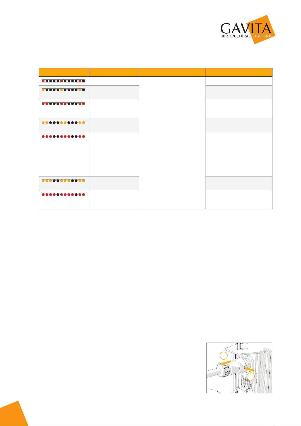
9.2 Error or warning indications
Status LED message Status luminaire Description Action / Solution
Too low voltage Input voltage is too low Check mains voltage
Too low voltage occured
in past
See above, reset
Too high voltage Input voltage is too high Check input voltage, check wiring
and connection, check neutral in
3 phase systems
Too high voltage occured
in past
See above, reset
Too high temperature Electronics temperature is too
high (max. 115 °Celsius )
Disconnect from mains. Check
installation, clean ballast, check
environment temperature (max
35 °Celsius). Make sure the
luminaire is not heated by HPS
lamp light. Wait until the lamp is
cooled down, then reconnect to
the mains.
Too high temperature
occured in past
See above, reset
No signal from
controller
Luminaire is connected to the
mains and set to EXT but there is
no signal on the control input.
If a controller is connected,
search for loose connections,
defect contacts or short-circuits.
10 Inspection, maintenance and repair
6Warning! Disconnect the product from mains before performing any maintenance or repairs.
6Warning! Do not connect or disconnect the Wieland RST20i3 plug under load.
6Warning! Do not open or disassemble the luminaire, it contains no servicable parts inside. Opening the luminaire can
be dangerous and will void the warranty.
6Warning! Always allow for a cool down period of at least 30 minutes before touching the lamp or reflector.
1Caution! Do not clean the luminaire with detergents, abrasives or other agressive substances.
1Caution! Do not touch the inside of the reflector during installation and do not use water, abrasives or detergents to
clean it. This will damage the reflective surface.
2Note: Gavita recommends to measure the lamp and reflector for aging every year. Replace the lamp and/or reflector
when they are aged.
• Regularly check the luminaire for dust or dirt buildup. Clean if necessary. Contamination may couse overheating and
decreased performance.
− Clean the inside of the reflector only with a soft, dry cloth;
− Clean the electronic ballast and the outside of the luminaire using a dry or damp cloth.
• Check the lamp monthly for discolorations or black markings. Always replace a damaged lamp.
1Note: Before initial use, the lamp could have black markings. This will disappear when the lamp runs on full power. If
not, replace the lamp.
• Regularly check the wiring of the product to ensure it is undamaged.
10.1 How to disconnect the Wieland RST20i3 plug
6Warning! Do not connect or disconnect the Wieland RST20i3 plug under
load.
1. Switch off mains power.
2. Press the pin on the Wieland RST20i3 male connection inwards and pull the
Wieland RST20i3 female connection from the luminaire (18).
B
B2
1
18

11
Pro line
Pro line
10.2 Placement and replacement of the lamp
6Warning! Always allow for a cool down period of
at least 30 minutes before touching the lamp or
reflector.
1Caution! Do not touch the lamp with bare hands
as this will damage the lamp. Always use a fabric
glove to handle the lamp.
1Caution! Only use lamps specified by Gavita (see
paragraph 3.3).
2Note: The lamp must be replaced every year or
after 5000 lighting hours, whichever one comes
first.
1. Switch off mains power.
2. Hold the lamp with a fabric glove to prevent it
from falling. Use a protective glove if the lamp is
damaged.
3. Open the lamp holders by sliding them outwards
(19).
4. Carefully take the lamp out of the luminaire (20).
5. Install the new lamp with the getter near the
ballast (21), with the glass vacuum seal pointed
downwards (Philips lamps) or sideways (Gavita
lamps).
Both lamp wires need to be placed straight into
the lamp holder and need to touch the metal part
of the lamp holder.
6. Close the lamp holders by sliding them inwards
(22).
7. Switch on mains power.
19
20
A
21
Click!
22

12
Pro line
Pro line
10.3 Placement and replacement of the reflector
6Warning! Always allow for a cool down period of
at least 30 minutes before touching the lamp or
reflector.
2Note: Gavita recommends replacing the
reflector* after 5000 lighting hours.
Depending on the environment and contamination
levels the reflector will degrade. The Vega Miro™
aluminum can not be cleaned without damage.
Therefore we recommend to change the reflector once
every year. Also replace the lamp when replacing the
reflector.
* The reflector is delivery dependent, it may differ
from the image.
1. Switch off mains power.
2. Remove the lamp from the luminaire (see
paragraph 10.2).
3. Support the reflector on the side of the reflector
lever to prevent it from falling (23).
4. Move the reflector lever up to retract the two pins
holding the reflector in place (24).
5. Remove the reflector (25).
6. Place the new reflector. Ensure the reflector lever
is in the opened position to allow the reflector to
pass.
7. Ensure the holes in the reflector are aligned with
the pins in the fixture (26).
8. Release the reflector lever so its two pins hold
the reflector in place.
9. Insert the lamp in the lamp holder (see
paragraph 10.2).
10. Switch on mains power.
23
24
25
26

13
Pro line
Pro line
11 Storage and disposal
• Store the luminaire in a dry and clean environment, with an ambient temperature of -20 ~ 85 °Celsius.
• The product must not be discarded as unsorted municipal waste, but must be collected separately for the purpose of
treatment, recovery and environmentally sound disposal.
1Caution! The lamps are chemical hazardous waste and must be delivered to the designated authorities.
1Caution! The lamp contains mercury.
12 Warranty
Gavita International bv warrants the mechanical and electronic components of their product to be free of defects in
material and workmanship if used under normal operating conditions for a period of three (3) years from the original date
of purchase. If the product shows any defects within this period and that defect is not due to user error or improper use
Gavita International bv shall, at its discretion, either replace or repair the product using suitable new or reconditioned
products or parts. For HPS lamps the warranty period is one (1) year from the original date of purchase. In case Gavita
International bv decides to replace the entire product, this limited warranty shall apply to the replacement product for the
remaining initial warranty period, i.e. three (3) years from the date of purchase of the original product. For service, return
the luminaire to your shop with the original sales receipt.


Gavita International BV
Naritaweg 8
1437 EL Rozenburg NH
The Netherlands
T +31(0)297-380 450
F +31(0)297-380 451
www.gavita.com
Pro line
Pro line
Manual: Gavita Pro 1000e 380-400V
Changes reserved - Version 21/11
Not for sales or use in the Netherlands
Other manuals for Pro 1000e
1
Table of contents
Other Gavita Lighting Equipment manuals

Gavita
Gavita Pro Series User manual

Gavita
Gavita GAN Electronic 600 W 230 V EU User manual

Gavita
Gavita Proline CT 2000e User manual

Gavita
Gavita GAN Electronic 750 W User manual

Gavita
Gavita DigiStar 400 User manual

Gavita
Gavita Pro line HortiStar 1000 DE EU User manual

Gavita
Gavita GAN Electronic 750 W 400 V DE EU User manual

Gavita
Gavita Pro RS 2400e LED User manual

Gavita
Gavita CT 1930e User manual


