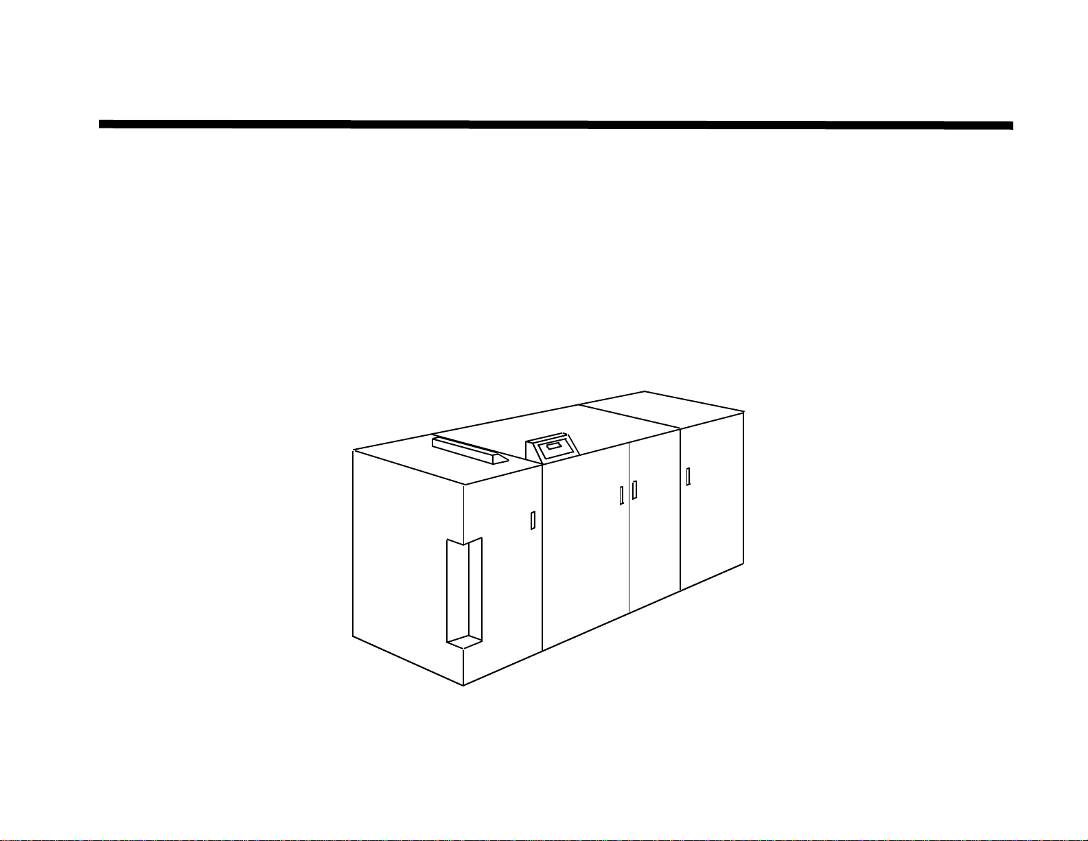
GBC FusionPunch II Service Manual
Table of Contents 12/2003
ii
Introduction
About this manual
This manual is part of the multinational
documentation that is structured in a specified
GBC format.
Organization
The Fusion Punch and Stacker Service
Manual is the primary document used for
repairing and maintaining the products. The
manual contains this information divided into
the following sections:
Section 1 Service Call Procedures
This section is used to identify the first
audible or visual symptom for the problem.
The procedures will then direct you to a
RAP or identify a faulty component or
subassembly.
Section 2 Status Indicator RAPs
This section contains Repair Analysis
Procedures (RAPs). You will be directed
to this section to isolate a faulty
component or subassembly.
Section 3 Quality RAPs
This section contains Quality Repair
Analysis Procedures (RAPs). You will be
directed to this section if the defect is
related to Punch or Stacker quality.
Section 4 Repairs / Adjustments
This section contains the instructions for
removal, replacement, and adjustment of
the spared parts within the machine.
Section 5 Parts Lists
This section consists of illustrations and
part number lists. Any part that is spared is
illustrated. Common hardware is
shown as a letter callout
Section 6 General Procedures
This section contains general procedures,
product specifications, supplemental tools,
supplies and modification information.
This section also contains Host
Enablement procedures and Personality
Profiles for Host Printer to Finisher.
Section 7 Wiring Data
This section contains illustrations and lists
of the signals and connectors. The
illustrations show the power, ground, and
the control signal distribution. The lists
show the signals and pin assignments for
all connectors.
Section 8 Installation Instructions
This section contains the instructions for
installation of the equipment.
Section 9 FusionPunch II User Guide
The FusionPunch II User Guide is a
separate publication that describes
operation and maintenance of the
FusionPunch II.
How to use this manual
Start and end all service calls with the Service
Call Procedures, Section 1. Perform Initial
Actions and the System Check to identify a
symptom.
Follow the instructions provided within the
Service Call Procedures and proceed to the
appropriate section of the manual.
After the repair is complete, verify the repair
with the System Check.
Terminology and Symbols
The following are the terminology and symbols
that are used in this manual for
Warnings, Electrostatic Device or
general Cautions, and Notes.
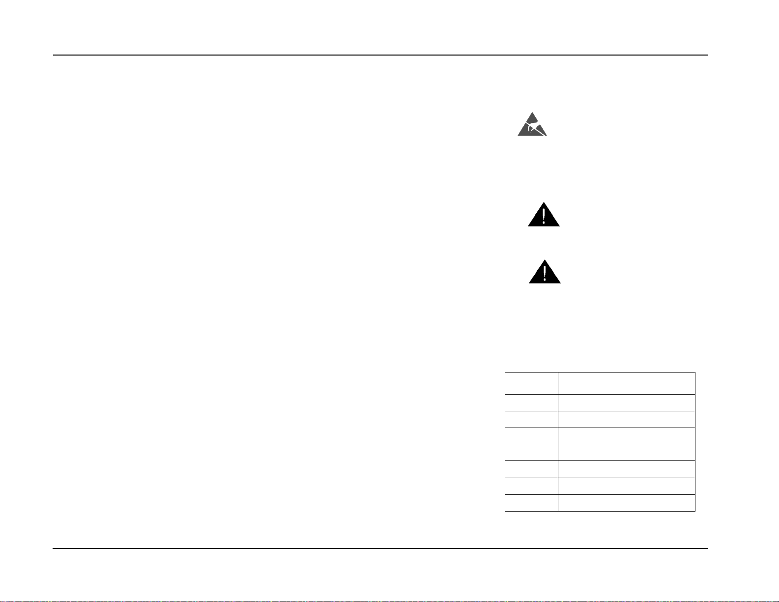
Electrostatic Discharge
Certain components in this product are
susceptible to damage from electrostatic
discharge. Observe all ESD procedures to
avoid component damage.
WARNING
Improper operation may result in
injury to a person.
CAUTION
Improper operation may result in
machine damage.
NOTE: Hints or other information that
may assist the user.
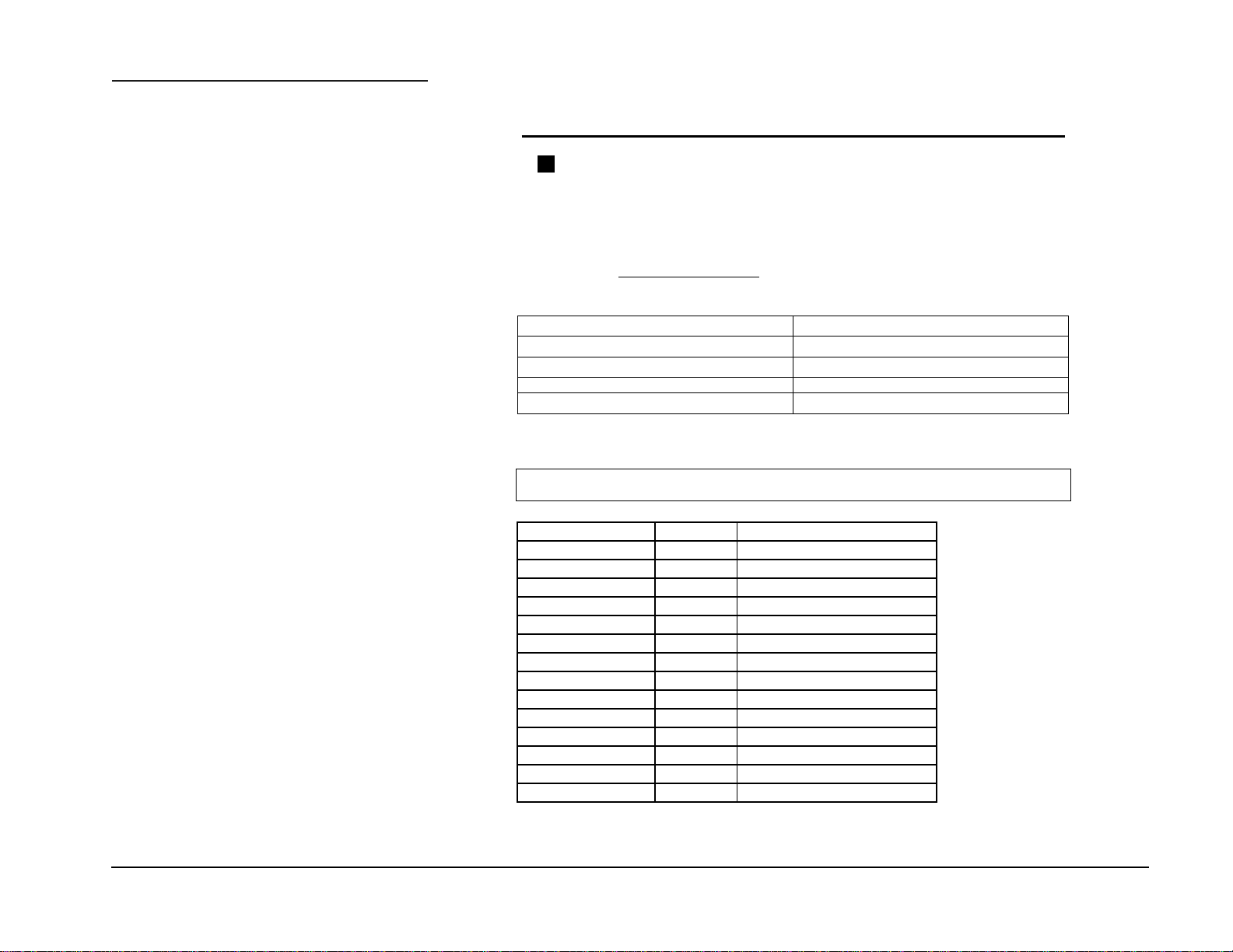
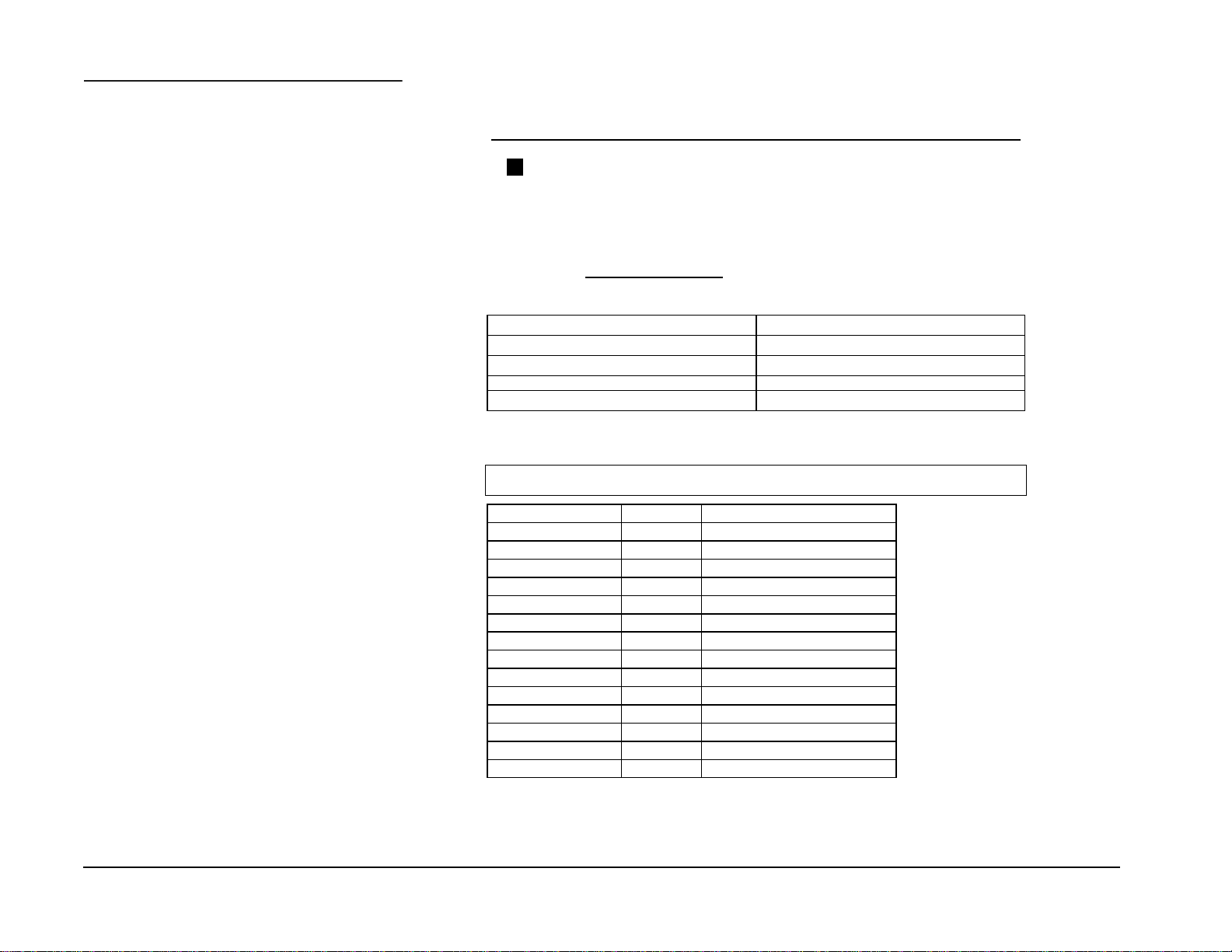
List of Abbreviations
Acronym Definition
BLK Black
BLU Blue
BRN Brown
GRN Green
ORG\ORN Orange
WHT White
YEL Yellow