GBF PL960M User manual

G B F
WiFi IP Doorbell
USER MANUAL

WELCOME
Congratulations on purchasing the GBF PL960 Series
to enable multiple security camera monitoring
through smart handheld devices and now have used
that expertise to bring you a full-featured IP Video
Doorbell system that allows you to monitor and interact
with visitors at your door, from anywhere your mobile
device has a Wi-Fi or data connection. Please read these
instructions carefully and follow all of the required steps
during setup to ensure your enjoyment of a fully
functional IP Doorbell system in minutes. You may connect
the PL960 Series of IP Doorbells to your LAN (Local Area
Network) either through a Wireless (Wi-Fi) connection or
a Wired (Ethernet Cable) connection. As with any video and
audio streaming device, wired connections are preferred
over Wi-Fi, but the convenience of not requiring wires from
your IP Doorbell location to your router may be the
determining factor in your installation.
Notes: GBF IP doorbell system only works with 2.4G hz
WiFi, not 5G hz WiFi.

CONTENTS
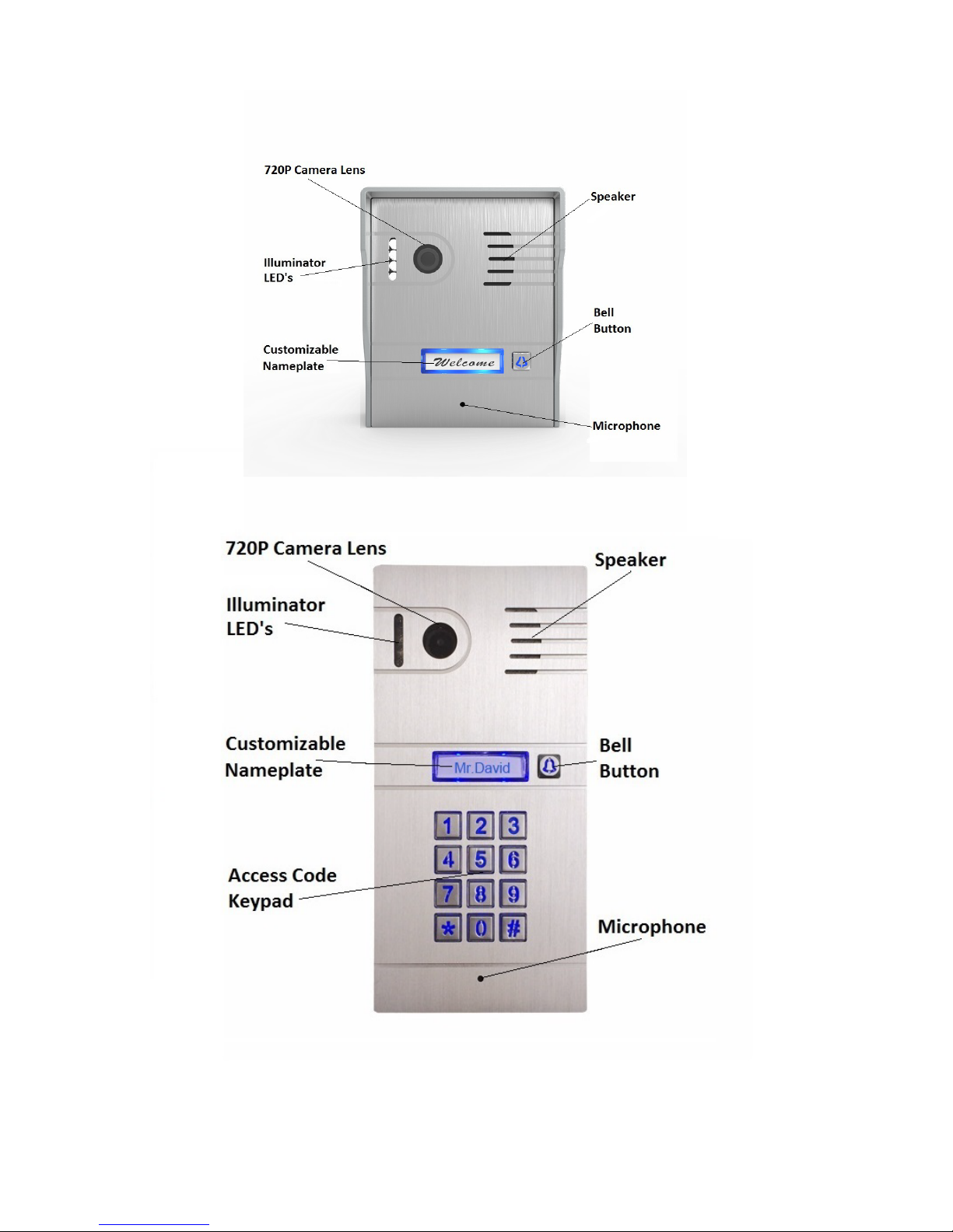
(1) GBF PL960M/PM IP Doorbell
(1) Metal Back Box
(1) External Wi-Fi Antenna with 3’ Cable
(1) 12VDC Power Supply
(1) RJ-45 Wired Ethernet Adapter Dongle
(1) Relay/Push-to-Exit Wiring Harness
(1) Bell Connector Wire Set
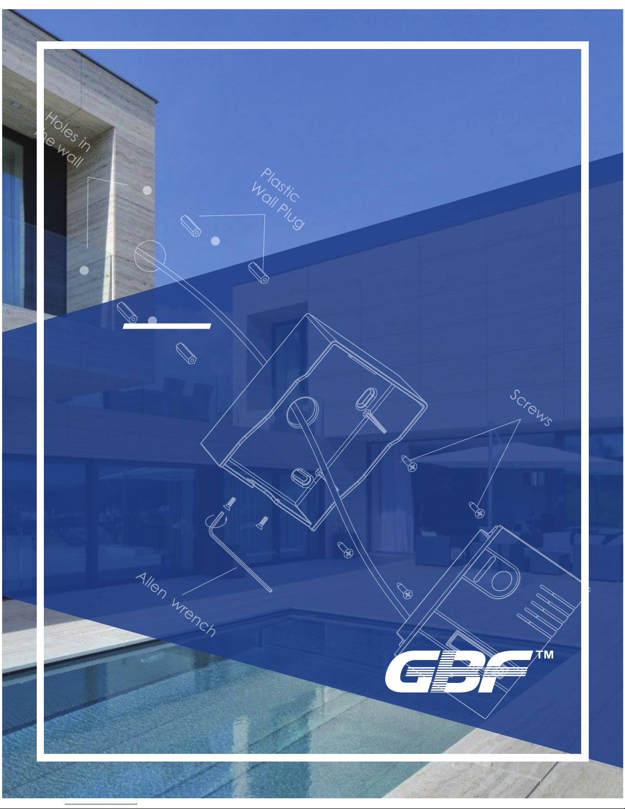
(4) Screws with Anchors
(2) Hex-Head Screws
(1) Allen Key
(1) Installation and Instruction Manual


1. Installation
*Note: It may be more convenient to perform the initial configuration of
the IP Doorbell with it temporarily connected to power nearby your
home internet router and a computer. This way testing and operation
can be verified before the unit is mounted permanently.
- Location: Choose a location for your new IP Doorbell, taking
into consideration sightlines, shadows, and excessive back -
ground lighting for the camera. You must also consider proxim-
ity to AC power and the ability to run wiring for additional
optional accessories. Optimal mounting height would be
approximately 60” (150cm) up from the surface that the caller
is standing on. Consider drilling a 1¼” diameter or larger hole
into the wall behind the IP Doorbell to allow for the conceal-
ment of the Wi-Fi antenna or RJ-45 Dongle within the wall.
- Back Box Mounting: Feed the power supply wiring, wiring
harness(s), and the Wi-Fi Antenna cable or the RJ-45 dongle
through the hole from the back side of the back box. Use the
four screws (and anchors, if required) supplied to mount the
back box to the wall in the desired location.
- Connect wiring harness and other connections to the back of
the IP Doorbell. Gently feed excess wiring through the hole in
the back box into the wall cavity, and place the IP Doorbell into
the back box (top first).
- Secure the IP Doorbell into the back box at the bottom
leading edge using the two supplied Hex-Head screws and
Allen key.

Rain Cover
Screws
Back case


2. Configuration
Begin by performing a factory reset of the settings in your
IP Doorbell. To default the settings to factory, follow these
steps;
- Apply power to the IP doorbell.
- Within 5 seconds, press and hold the ‘Bell’ button until your
hear a distinctive 1 second long buzzer sound (after approxi-
mately 1 minute, it is preceded by a flash of the illuminator
LED’s). Release the ‘Bell’ button after the buzzer sound stops.
- The IP Doorbell will reset once again (about one minute) and
is ready to start configuration shortly after the illuminator LED’s
flash.
*Note: Performing a factory reset erases settings stored during
the setup process. Do not perform a factory reset after you have
red the IP Doorbell unless absolutely necessary.
*To Proceed with a Wireless (Wi-Fi) installation, go to step 3a.
*To Proceed with a Wired (RJ45) installation, complete step 3a,
then connect the RJ45 cable.
*To Proceed with a Wired (RJ45) installation without any
requirement for a Wi-Fi connection credentials, star
step 3b (advanced).
configu
t at

2. Outdoor station configuration
Downloading the App
To configure and receive calls from the Outdoor Station you need to
download the ControlCam2 Application. Available on Google Play
Store (Android) and Apple App Store (iOS).
ControlCam2
Notes:
The ControlCam2 app is free to use.
Keep the ControlCam2 app updated.
The application is subject to changes whit no prior notification.
Preparing the App to be used
1. Make sure your smartphone is connected to your Wi-Fi network.
2. Open the app.
3. Click on the ‘Sign up’ button.
4. Enter a username, password, password confirmation, custom
question and answer the custom question.
5. Read the terms and privacy, then click on the checkbox, agreeing
with.
6. Click on ‘Sign up’ button. If the provided information is ok, a popup
message will appear on the screen with ‘Registration Success’, then
click on ‘OK’.
7. You will be redirected to the login screen.
8. Click on ‘Login’. Now you are logged into your account and can see
your home screen.

2.1 Adding devices to your ControlCam2
account
Configuring a new device
Before configuring a new device (Outdoor station or Skybox), it is
necessary to perform the factory reset.
1. With the device powered on, Hold the ‘call’ button on Outdoor
Stations or ‘reset’ button on Skyboxes for 1 minute.
2. The device’s LEDs will flash. After, a long beep can listen.
3. When the LEDs light on means the factory reset was performed
successfully.
Then, you can continue configuring your device, using the smartphone.
2.1.1 Configuring a new device using Android
1. Wait 2 minutes after the factory reset, allowing the device to restart
properly.
2. Make sure your smartphone is connected to the Wi-Fi network in
which the device (Outdoor Station or Skybox) will work on.
3. Inside the app, click on the floating “add” button.
4. Choose the ‘Configure via Wi-Fi’ option.
5. Click ‘Next’ to start searching automatically the new device on the
network. When found, a popup window will appear showing the Wi-Fi
network and asking its password. (If the search finds more than one
new device, a popup screen will appear showing the identification of
each one. Choose the desired one, looking on the GID label placed on
the device).
6. Enter the Wi-Fi password, and press ‘OK’.
7. A popup message will appear, showing the device was configured
successfully, press ‘OK’ to confirm.
8. In the device’s details screen, insert the default password ‘1234’,
change the device’s name to the desired name, and press ‘Save’. (Do
not change the GID identification).
9. Now you can see the device’s image on the ‘Home screen’. To
access it, click on its image or its identification.

Once the Device has been added to the app, you will be able to
access it by Wi-Fi or mobile data (3G/4G).
3.1.2 Configuring a new device using iOS
1. Wait 2 minutes after the factory reset, allowing the device to restart
properly.
2. Make sure your smartphone is connected to the Wi-Fi network in
which the device (Outdoor Station or Skybox) will work on.
3. Inside the app, click on the “add” button.
4. Choose the ‘Configure via Wi-Fi’ option.
5. Press on ‘Configuration’.
6. The name of the Wi-Fi network will appear, and the app will ask its
password to continue.
7. Enter the Wi-Fi password. (Do not press ‘Next’ yet)
8. Go to the Smartphone’s Wi-Fi configuration (outside the
ControlCam2 app), and look for the device identification (It will appear
as ‘LID + GID identification’. The identification can be consulted
looking on the GID label placed on the device).
9. Go back to the ControlCam2 application and click on ‘Next’.
10. In the device’s details screen, insert the default password ‘1234’,
change the device’s name to the desired name, and press ‘Save’. (Do
not change the GID identification).
11. Now you can see the device’s image on the ‘Home screen’. To
access it, click on its image or its identification.
Once the Device has been added to the app, you will be able to
access it by Wi-Fi or mobile data (3G/4G).
3.2 Adding a previously configured or wired
device
You can add a previously configured or wired device through three
methods: LAN search, QR code scan and manually.
1. Connect to the Wi-Fi network which contains the device.
2. Inside the app, click on the “add” button.
3. Choose the ‘Add Device Directly’ option.
4. On the ‘Add Device’ screen, choose one of the following methods.

LAN Search
5. Press the ‘Lan Search’ button.
6. A list of all devices in the network will appear, click on the desired
one.
7. On the ‘Add Device screen’ will appear the information from that
device.
8. insert the password (default password is ‘1234’), change the
device’s name to the desired name, and press ‘Save’. (Do not change
the GID identification).
9. Now you can see the device’s image on the ‘Home screen’. To
access it, click on its image or its identification.
QR Code Scan
5. Press the ‘QR CodeScan’ button.
6. Accept the popup message to allow the app to access your camera.
7. Using the camera, look on the QR code placed on the device.
8. On the ‘Add Device screen’ will appear the information from that
device.
9. insert the password (default password is ‘1234’), change the
device’s name to the desired name, and press ‘Save’. (Do not change
the GID identification).
10. Now you can see the device’s image on the ‘Home screen’. To
access it, click on its image or its identification.
Manually
5. Manually insert the device's GID. The identification can be
consulted looking on the GID label placed on the device
6. Enter the default password ‘1234’.
7. insert the password (default password is ‘1234’), change the
device’s name to the desired name, and press ‘Save’. (Do not change
the GID identification).
8. Now you can see the device’s image on the ‘Home screen’. To
access it, click on its image or its identification.
NOTES:
•It is possible to add an unlimited number of devices to your app.
•Each device will support up to 4 concurrent connections.

3. Keypad Programming (PL960PM Model)
The
PL960PM
keypad can be custom programmed with up to 40 different
access codes, and will trigger the same relay that is triggered through the
ControlCam App. The length of the access codes and programming pass-
word can be programmed to be two to six digits in length (globally).
However, the master password and unlock delay times set in the keypad
are independent of the IP Doorbell. A factory reset of the IP Doorbell will
not affect the programming contained in the keypad and vice versa. The
keypad requires a separate factory reset to clear the programming.
Modify the Programming Password:
1. Disconnect power to the IP Doorbell.
2. Restore the power to the IP Doorbell. Two short chirps will be
heard.
3. Within 3 seconds press the ’*’ button.
4. Enter the new password (length determined through other
programming). A longer beep is heard, indicating the new password has
been successfully stored.
5. Press’*’ to exit the programming mode.
Enter Programming Mode:
1. Press the ‘*’ button, a chirp is heard.
2. Enter the programming password (default is 1234). A longer beep is
heard, indicating the IP Doorbell is now in programming mode.
3. The IP Doorbell will automatically exit programming mode if there is no
input at the keypad for over 30 seconds or press ‘*' to exit programming.
Set Unlock Duration Time:
1. Enter programming mode.
2. Press ‘00’, a longer beep is heard.
3. Enter two digits (01 – 99) representing the new unlock duration time,
in seconds. A longer beep is heard confirming the change.
4. Press ‘*’ to exit the programming mode.

Add User Access Codes:
1. Enter programming mode.
2. Enter two digits (01 – 40) representing the slot in which the user
code will reside, a longer beep is heard.
3. Enter the new user code (length determined through other
programming); another longer beep will indicate the new code was
stored successfully.
4. Press ‘*’ to exit the programming mode.
*Note: Slots 31 – 40 are not affected by the programmed unlock duration
time. These access codes will only trip the relay for about 1second.
Delete User Access Codes:
1. Enter programming mode.
2. Enter two digits (01 – 40) representing the slot containing the access
code you want to delete. A longer beep is heard.
3. Press the ‘#’ button, another longer beep is heard confirming the deletion.
4. Press ‘*’ to exit the programming mode.
Delete User Access Codes Directly:
1. Enter programming mode.
2. Press ‘#’, two short chirps are heard.
3. Enter the access code you want to be deleted, a longer beep is heard
confirming deletion of the access
code.
4. Press ‘*’ to exit the programming mode.
Setting the Length of the Access Codes and Programming Password:
1. Enter the programming mode.
2. Press ‘99’, a longer beep is heard.
3. Enter a single digit (2 – 6) representing the desired length of the access
codes and programming password, and a longer beep is heard confirming
the change.
4. Press ‘*’ to exit the programming mode.

Delete All Settings (Maintains Programming Password):
1. Enter programming mode.
2. Press ‘#’, two short chirps can be heard.
3. Press’#’ again, a longer beep can be heard.
4. Press ‘#' again seven more times. After three seconds another longer
beep will be heard confirming deletion of all User codes and resetting
the unlock duration time back to 1 second. Programming password and
length will remain unchanged.
5. Press’*’ to exit the programming mode.
Factory Reset (Custom Keypad Settings Only):
1. Disconnect power to the IP Doorbell.
2. Restore the power to the IP Doorbell. Two short chirps will be heard.
3. Within 3 seconds, press the '#' button. A longer beep is heard, indicating
the keypad programming has been restored to factory default settings.
4. Using the ControlCam2 App
4.1. Device’s Settings
From the device’s setting screen is possible to adjust some
settings to the device.
Access the ‘Device’s setting screen’ according to the smartphone
you are using:
Using an Android smartphone or tablet, from the ‘Home
screen’ swipe the device’s image to the left, and click on the
‘edit’ button.
Using an iOS smartphone or tablet, from the ‘Home screen’
click on the ‘engine’ button.

Changing device’s name, username and password
When desired you can change the device’s username and
password, or after another user has changed, it is necessary to
change on the other users.
1. In the ‘Device’s setting screen’ enter the new information
(username and/or password, and name if desired).
2. Press ‘Save’.
3. The app will go back to the ‘Home screen’ and the device will be
actualized with the new information.
Unlock Time
It is possible to change the time which the auxiliary contact for gate
opener will be activated.
1. In the ‘Device’s setting screen’ enter the new unlock time (1 -100
seconds, where the default is 1 second), and press ‘OK’.
2. Press ‘Save’.
3. The app will go back to the ‘Home screen’ and the device will be
actualized with the new unlock time.
One-Key Unlock
To activate the device’s auxiliary contact (gate opener) from the
app without the necessity to enter the ‘unlock password’, it is
necessary to activate the ‘One-Key Unlock’ option (it requires you
have set an ‘unlock password’).
1. In the ‘Device’s setting screen’ click on the ‘One-Key Unlock’
button.
2. Press ‘Save’.
3. The app will go back to the ‘Home screen’ and the device will be
actualized with the new unlock time.
4.2. Advanced Device’s Settings
On the ‘Device’s setting screen’ click on the ‘Advanced Settings’
button.
Modify Device Password
It is possible to change the access password (which the device

request to the app each time it is accessed).
1. In the ‘Advanced Settings screen’ click on ‘Modify Device
Password’.
2. Enter the ‘device password’ (current), then insert the ‘new
password’ and the ‘password confirmation’.
3. Press ‘Save’.
4. Exit the ‘Device’s Settings Screen’.
Note: It is a good feature for building managers. During a change of
tenants, there is only the necessity to change the device password
and offer the device’s GID and new password for the new tenant,
blocking the access to the old tenant.
Modify Unlock Password
A password is required to activate the device’s auxiliary contact
(gate opener) from the app. This step is also required to allow the
‘One-Key Unlock’ function.
1. In the ‘Advanced Settings screen’ click on ‘Modify Unlock
Password’.
2. Enter the ‘unlock password’ (current) (the default is 1111), then
insert the ‘new password’ and the ‘password confirmation’.
3. Press ‘Save’.
4. Exit the ‘Device’s Settings Screen’.
Motion Detection
The app ControlCam2 allows you to set directly a motion detector
alarm for your device. It allows monitoring your device even when
a person does not press the call button.
1. In the ‘Advanced Settings screen’ click on ‘Motion Detection’.
2. Click on the ‘On/Off’ button.
3. Press ‘Save’.
4. Exit the ‘Device’s Settings Screen’.
Set Time
To improve your experience with the device, keep its time
synchronized with your smartphone.
1. In the ‘Advanced Settings screen’ click on ‘Set Time’.

2. A popup message will appear. Then click on the ‘Ok’ to confirm.
3. Exit the ‘Device’s Settings Screen’.
Reboot/Restore
In case of malfunction of your device, you can try to troubleshoot it
using this option. Use Reboot to force a reset on the device, and
Restore to force a factory reset.
1. In the ‘Advanced Settings screen’ click on ‘Reboot/Restore’.
2. Select the desired option ‘Reboot’ or ‘Restore’.
2. A popup message will appear. Then click on the ‘Ok’ to confirm.
3. Exit the ‘Device’s Settings Screen’.
4.3. Deleting a device from the app
1. Click on the ‘delete’ button
Using an Android smartphone or tablet, from the ‘Home
screen’ swipe the device’s image to the left, and click on the
‘trash bin’ icon.
Using an iOS smartphone or tablet, from the ‘Home screen’
click on the ‘trash bin’ button on the device.
2. A popup notification will appear, asking you to confirm. Click on
‘OK’
3. The device will be removed from the account in use, but it will
still be configured and connected to the local network and other
ControlCam2 accounts which have this device.
4.4. ControlCam2 Operations
Answering a call
When the visitor presses the call button on the outdoor station, your
smartphone will receive a ring notification. (Make sure to enable
notifications from the app to your smartphone). You can 'Accept' or
'Decline' on the pop-up call alert of the app.
If accept, use the following steps to have a conversation with the
visitor
1. Press on the microphone icon and the audio from the outdoor

station and the ‘Push to talk’ microphone will be enabled.
2. Press and hold the ‘Press to Talk’ button to talk with the visitor.
Unlocking the Door
During a call or monitoring mode, click on the ‘locker’ button to
activate the gate opener
1. Press the ‘locker’ button on ‘device’s home screen’ to unlock
the door.
2. If the ‘One-Key Unlock’ is not turned on, a popup message will
ask you to enter the unlock password (default is ‘1111’).
3. The door will unlock during the configured unlock time.
Monitoring the Outdoor Station
At any time, from the ‘Home screen’ click on a device’s image to
access the live stream from the outdoor station. The monitor mode
allows you to access all the option than during a call (take a
snapshot, record video, listen the outdoor station sound and talk
through the outdoor station microphone.
Image Capture
During a call or monitoring mode, click on to take a snapshot
of the outdoor station’s image. It can be accessed from the home
screen’s menu, in ‘Media’.
Video record
During a call or monitoring mode, click on icon to start
recording a video from the outdoor station’s image. Click again to
finish the record. It can be accessed from the home screen’s
menu, in ‘Media’.
Accessing recorded videos/images
1. From the device home screen, click on the main menu icon.
This manual suits for next models
1
Table of contents
Other GBF Accessories manuals
Popular Accessories manuals by other brands

Invacare
Invacare 1036793 Assembly, installation and operating instructions

Connect SmartHome
Connect SmartHome CSH-PLGUSBPM manual

UPPAbaby
UPPAbaby Upper Adapters quick start guide

optonica
optonica SE7301 manual

HAUL MASTER
HAUL MASTER 30329 operating instructions

Panasonic
Panasonic EQ-500 Series instruction manual