GBF PL963 Series User manual

USER MANUAL
411000261
G B F
WiFi IPDoorbell
(3rd Gen)

WELCOME
Congratulations on purchasing the GBF PL963 Series of smart IP
Door Station. Our factory engineers were the first to enable
multiple security camera monitoring through smart handheld
devices and now have used that expertise to bring you a full-
featured IP Video Doorbell system that allows you to monitor and
interact with visitors at your door, unlocking your gate from
anywhere your mobile device has a WiFi or data connection.
Please read these instructions carefully and follow all of the
required steps during setup to ensure your enjoyment of a fully
functional IP Doorbell system in minutes. You may connect the
PL963 Series of IP Doorbells to your LAN (Local Area Network)
either through a Wireless (WiFi) connection or a Wired (Ethernet
Cable) connection. As with any video and audio streaming device,
wired connections are preferred over WiFi, but the convenience of
not requiring wires from your IP Doorbell location to your router
may be the determining factor in your installation.
Note: The GBF IP Doorbell System only works with 2.4GHz WiFi
and is incompatible with 5GHz WiFi. You might also use hardwired
Rj45 cable or POE connection for this system as well.
1

PACKAGE CONTENTS
(1) GBF POE IP Door Station PL963PM/963M
(1) Metal Back Box
(1) External Wi-Fi Antenna with 3’ Cable
(1) 12VDC, 1A Power Supply
(1) Relay/Push-to-Exit Wiring Harness
(1) Bell Connector Wire Set
(1) Varistor (blue case, see wiring diagrams)
(4) Screws with Anchors
(2) Hex-Head Screws
(1) Allen Key
(1) Installation and Instruction Manual.
2

1. Installation
*NOTE: It may be more convenient to perform the initial
configuration of the IP Doorbell with it temporarily connected to
power nearby your home internet router and a computer. This way
testing and operation can be verified before the unit is mounted
permanently.
-Location: Choose a location for your new IP Doorbell, taking into
consideration sightlines, shadows, and excessive back - ground
lighting for the camera. You must also consider proximity to AC
power and the ability to run wiring for additional optional
accessories. Optimal mounting height would be approximately
60” (150cm) up from the surface that the caller is standing on.
Consider drilling a 1¼” diameter or larger hole into the wall
behind the IP Doorbell to allow for the concealment of the Wi-Fi
antenna (if used) within the wall.
-Back Box Mounting: Feed the power supply wiring, wiring
harness(s), and the Wi-Fi Antenna cable or the RJ-45 cable
through the hole from the back side of the back box. Use the
four screws (and anchors, if required) supplied to mount the back
box to the wall in the desired location.
-Set the desired unlock duration time using the switch on the
back of the IP Doorbell, and then connect the wiring harness and
other connections to the back of the IP Doorbell. Gently feed
excess wiring through the hole in the back box into the wall
cavity, and place the IP Doorbell into the back box (top first).
-Secure the IP Doorbell into the back box at the bottom
leading edge using the two supplied Hex-Head screws and
Allen key.
3

Back case
S
crews
4

POWER
1
2
3
4
5
LAN
RESET
2
BELL
ON=5S
OFF=1S BELL
Black w/White Stripe(+)
Black(-)
12VDC/1000mA
Plug-In
Transformer
(Supplied)
Wiring Diagram for Power Supply Connections and
Connection to Existing Door Chime (Optional)
*
1
+
-
-press and hold for 3 seconds until you hear Di sound,
device will reboot and enter WiFi configuration status
within 2 minutes.
-press and hold for 10 seconds until you hear DiDi
sound, device will be factory default within 2 minutes.
-press and hold for 15 seconds until you hear DiDi
DiDi DiDi sound, device will be unbinded.
1
2
3
4
5
5
PL963M/PMLockandBellRelaysareRatedMaximum3Ampsat250VACor30VDC
LOCK1
LOCK2
POWER
1
2
3
4
5
LAN
RESET
2
BELL
ON=5S
OFF=1S
1
+
-
*
Red
Black
Green(NormallyOpen)
Blue(Common)
Brown(NormallyClosed)
PushtoExitButton(optional)
Varistor
(MOV)
Lock
Power
Supply
Electronic
Lock
POWER
1
2
3
4
5
LAN
RESET
2
BELL
ON=5S
OFF=1S
1
+
-
*
Red
Black
Green(NormallyOpen)
Blue(Common)
Brown(NormallyClosed)
PushtoExitButton(optional)
Lock
Power
Supply
Electronic
Lock
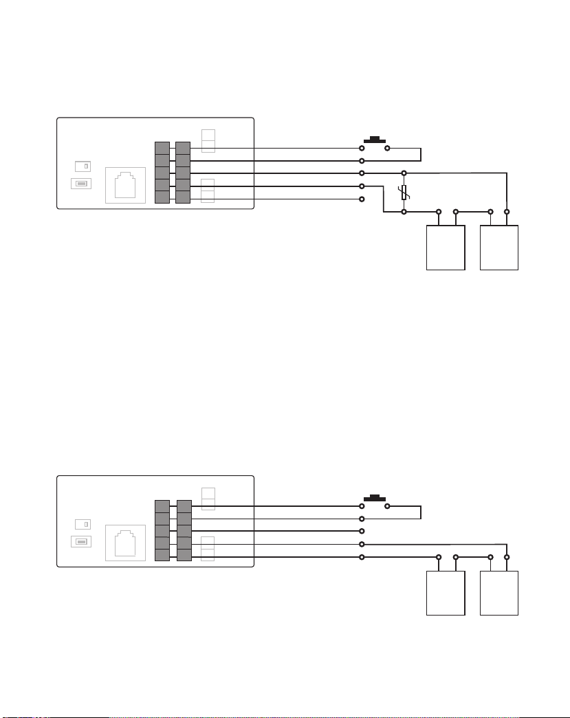
Wiring Diagram for Normally Closed Circuit
(e.g. Electronic Mag Lock)
Wiring Diagram for Normally Open Circuit
(e.g. Electronic Door Strike or Deadbolt)
1
2
3
4
5
1
2
3
4
5
6
PL963M/PMLockandBellRelaysareRatedMaximum3Ampsat250VACor30VDC
Please be advised that LOCK1 could be triggered by APP and Access Codes,
but LOCK2 could be triggered ONLY by APP, not Access Codes.
If you only use this system for one Door, please connect LOCK1 for your application.
LOCK1
LOCK2
LOCK1
LOCK2
PL963M/PMLockandBellRelaysareRatedMaximum3Ampsat250VACor30VDC
Please use LOCK1 for your gate control connection if this system is for controlling one door/ gate

2. Configuration Preparations
Begin by performing a factory reset of the settings in your IP
Doorbell. To reset the device to factory default setting, follow these
steps;
1. Connect the WiFi antenna with outdoor station or connect your Router
directly to the IP Doorbell with an ethernet cable.
2. This device has a Poe built-in, you could directly power this device with RJ45
cable through POE switch. Or use the power adapter in the package to
power this device. It requires 12V DC 1A power supply to work properly.
3. Within 30 seconds, press and hold the ‘Reset’button on the back
of the device for 15 seconds until you hear 3 beeps sound.
Then release the reset button.
*NOTE: Performing a factory reset erases settings stored during the
configuration process. Do not perform a factory reset after you have
configured the IP Doorbell unless absolutely necessary.
Downloading the App
To configure and receive calls from the Outdoor Station you need to
download the Doordeer APP. Free downloading are available onthe Google
Play Store (Android) and the Apple App Store (iOS)
Note:
-The Doordeer APP is free to use.–Please keep the Doordeer APP
updated.
-The applications is subject to change without notice.
Preparing the App to be used
*NOTE: It is best practice to restart your phone and disable its
cellular data and Bluetooth during the initial configuration of
the IP Doorbell.
1. Make sure your smartphone is connected to the 2.4G WiFi
network to which you want the GBF IP Doorbell to be connected.
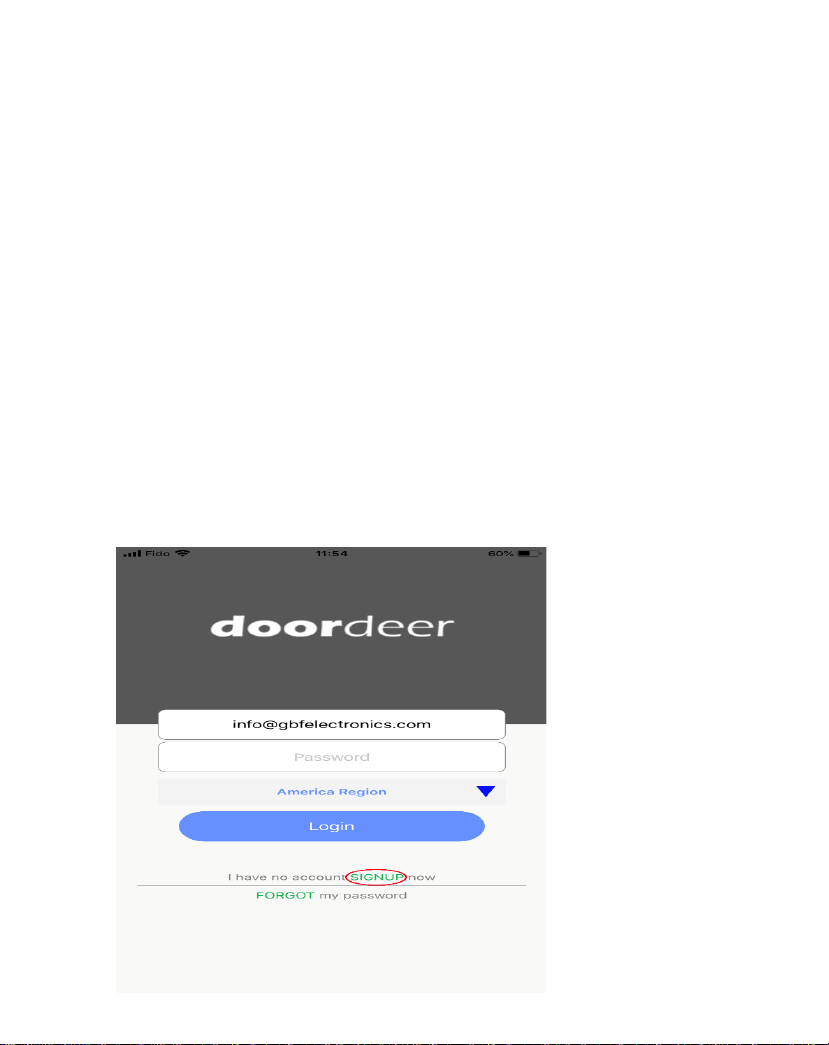
2. Open Doordeer APP.
3. Create an account by clicking on the “Sign Up”.

*NOTE: Every mobile device requires a separate APP account
for accessing this smart IP door station.
4. Enter a username (email address is required), password, password
confirmation.
5. Read the terms and privacy agreement, then click on the checkbox
to agree.
6. Click on ‘Sign up’button. If the provided information is valid and
the username does not already exist, a popup message will appear
on the screen with ‘Registration Success’, then click on ‘OK’.
7. You will be redirected to the login screen.
8. Click on ‘Login’. Now you are logged into your account and can see
your home (‘Doorbell’) screen.
*To Proceed with a Wireless (Wi-Fi) installation, go to step 3.1.1
(android) or 3.1.2 (iOS).
*To Proceed with a Wired (RJ45) installation, connect the RJ45
cable between your router and the IP Doorbell, then complete
step 3.2.
3. WiFI AP Configuration
3.1. Configuration Using the Android or iOS
App
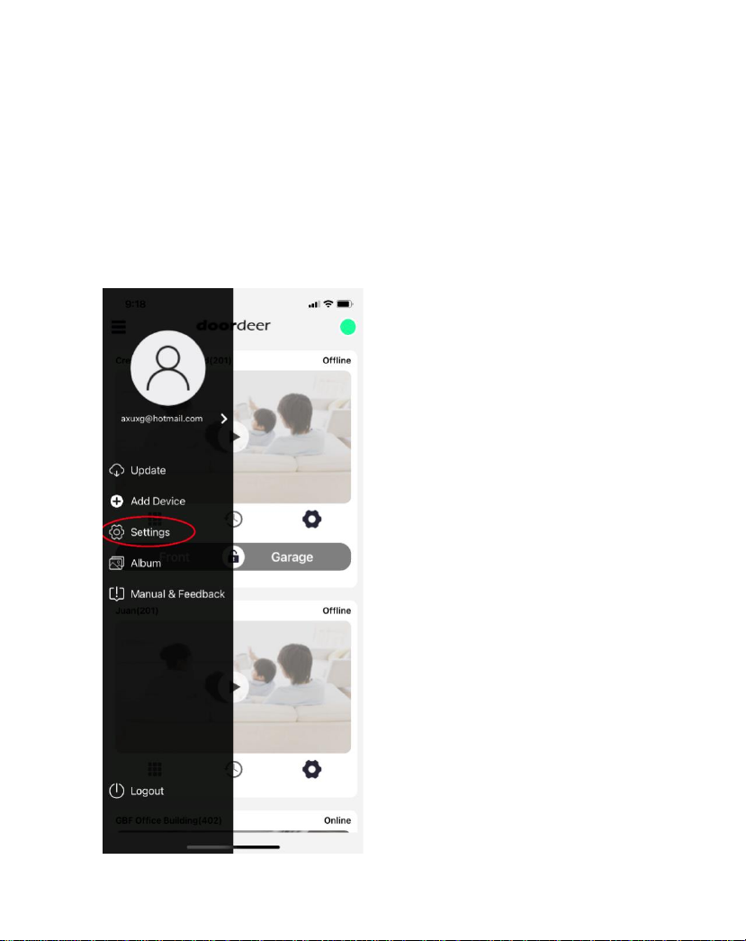
1. Inside the app, click Settings on the menu.

2. In the APP settings Page, Select AP Configuration. Then in
AP Configuration Page, Click “CONTINUE”.

3. You will see there are three steps for AP
configuration.
Leave Doordeer APP and go to your smart phone WiFi
settings, and find GBF door station hotspot which starts
at: cctvp2p- xxxxxxx. Then connect your smart phone to
this door station wifi.
Note: If you don’t find cctvp2p-xxxxxxx, you can
turn to the back, press the reset button and hold it for 15
seconds until hear three beep to reset this device again.
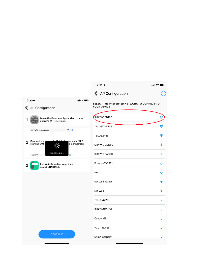
4. After you successfully connect your smart phone to
this door station WiFi, go back to Doordeer APP AP
Configuration mode again, the APP will automatically
search your local 2.4G wifi. Then Click your local 2.4G
wifi. If you do not see your local wifi name, just wait
about 30 seconds around, click the refresh button on
the top right corner, your local wifi name will be
shown up, then click that and add your wifi password.

5. Add your local wifi password and click “START
CONFIGURATION”. Then the APP will automatically search
the device and you will hear one “Ding” sound from this
door station. The message bar will be shown up for you to
Add Device. Click “Add Device”. In the LAN Search page,
you will find this door station ID and click the device.

6. Naming your door station such as “Front Door”, then click
“CONTINUE”. Your door station will be successfully added
into your Doodeer APP account. This new model has two
unlocking relays to unlock two different locks, so you will
see lock1 and lock2 and then you can choose to unlock
which lock by swiping the lock button.
3.2 Adding a configured or wired IP Doorbell
You can add a previously configured or hard wired IP Doorbell
device using the following method.
1. Connect your mobile device to the Wi-Fi/LAN network
which contains the IP Doorbell.
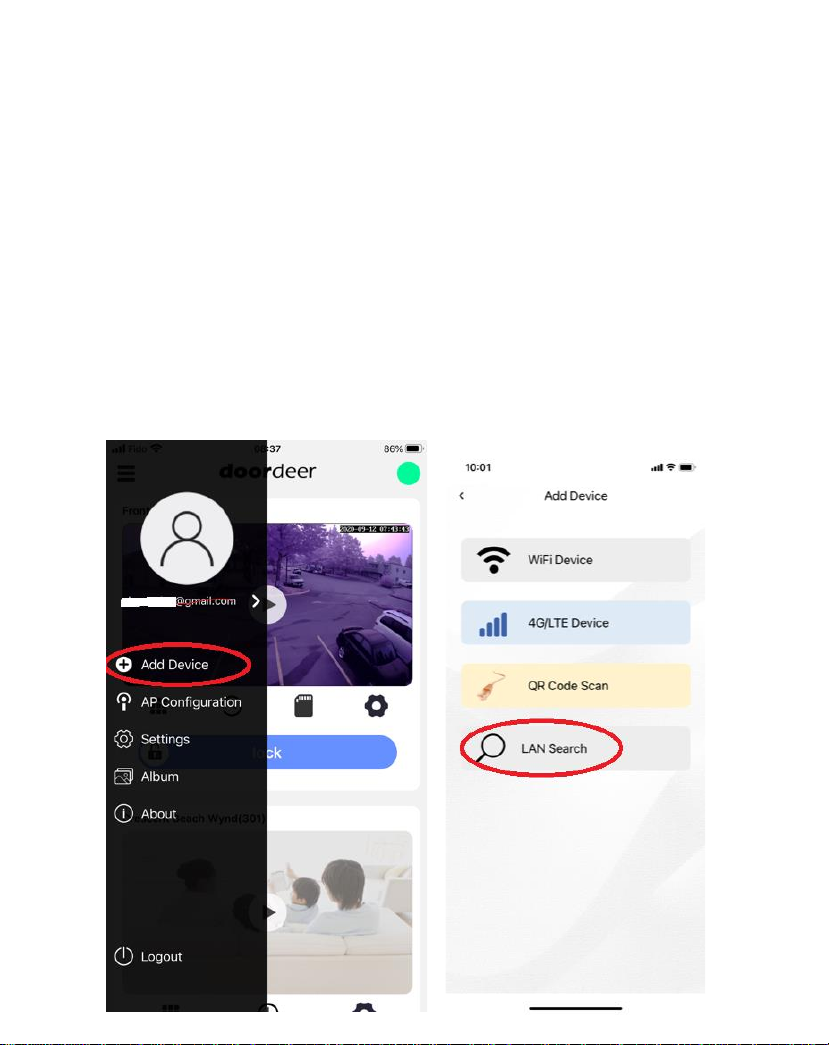
2. Clip the top left corner three black line, the menu bar is
shown up. Click Add Device. Then Select LAN Search, the AP will
automatically start to search the new device for you.

3. The new device will be shown on the device list. Click the new
device and Name your device, then click “Confirm” to add your
device successfully on Doordeer APP.
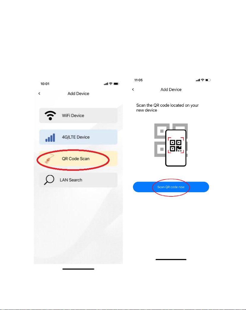
4. You could also add your device by QR Code Scan. There is one
QR code label on the back of the device. The device GID no. is
under this QR code. You could use QR code scan the QR code
and add the new device if you are not in the same network with
the device.
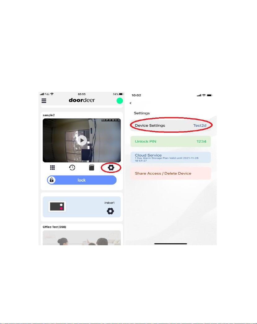
4. Settings
Inside the app, click setting symbol on the device window.
The APP shows Setting Page which includes Device Setting
Option, Unlock Pin, Cloud Service and Share Access…
To use PIN Code to unlock the door, Press # + PIN CODE + #
will trigger the device relay to unlock your door.
The PIN Codes only work for LOCK1, not LOCK2. If your PIN
Codes do not trigger your door lock, please check the
device connection port to make sure to use LOCK1 port for
your application.
Other manuals for PL963 Series
1
Table of contents
Other GBF Accessories manuals


