Gbord ES-800 User manual

`
ES-800
PCIe 8S Serial Card
User’s Manual
1st Ed –24May 2019
Overview
Icon Descriptions
The icons are used in the manual to serve as an
Indication of interest topics or important messages.
Below is a description of these icons:
NOTE: This check mark indicates that there
is a note of interest and is something that
you should pay special attention to while
using the product.
WARNING: This exclamation point
indicates that there is a caution or warning
and it is something that could damage your
property or product.
Online Resources
The listed websites are links to the on-line product
information and technical support.
http://www.gbord.com/
Copyright and Trademarks
This document is copyrighted, © 2018. All rights are
reserved. The original manufacturer reserves the right to
make improvements to the products described in this
manual at any time without notice.
No part of this manual may be reproduced, copied,
translated or transmitted in any form or by any means
without the prior written permission of the original
manufacturer. Information provided in this manual is
intended to be accurate and reliable. However, the
original manufacturer assumes no responsibility for its
use, nor for any infringements upon the rights of third
parties that may result from such use.
Acknowledgement
Intel, Pentium and Celeron are registered trademarks of
Intel Corp.
Microsoft Windows and MS-DOS are registered
trademarks of Microsoft Corp.
All other product names or trademarks are properties of
their respective owners.
Compliances and Certification
CE Certification
This product has passed the CE test for environmental
specifications. Test conditions for passing included the
equipment being operated within an industrial enclosure.
In order to protect the product from being damaged by
ESD (Electrostatic Discharge) and EMI leakage, we
strongly recommend the use of CE-compliant industrial
enclosure products.
FCC Class A Certification
This equipment has been tested and found to comply
with the limits for a Class A digital device, pursuant to
Part 15 of the FCC Rules. These limits are designed to
provide reasonable protection against harmful
interference when the equipment is operated in a
commercial environment. This equipment generates,
uses, and can radiate radio frequency energy and, if not
installed and used in accordance with the instruction
manual, may cause harmful interference to radio
communications. Operation of this equipment in a
residential area is likely to cause harmful interference in
which case the user will be required to correct the
interference at his own expense.
Revision History
Version
Date
Descriptions
0.1
2019.05.24
Preliminary

Table of Contents
Chapter 1: Introduction .........................................................................................................................4
1.1 Module Physical Features ............................................................................................................ 4
1.2 System Requirements.................................................................................................................. 4
1.3 Package contents ........................................................................................................................ 4
Chapter 2: Installation ........................................................................................................................... 5
2.1 Hardware Installation ................................................................................................................... 5
2.2 Pin Assignment ...........................................................................................................................5
2.3 Driver Installation .................................................................................................................................7
Chapter 1: Introduction
RS-232 I/O series, a line of PCI Express Multi-port Serial Communication Board, is designed to meet PCI Express
Base Specification V2.0. It can be installed in virtually any available PC system and compatible with all major operating
systems. Users do not need to manually set jumpers to configure I/O addresses and IRQ locations.
This board offer independent serial ports for connecting terminals, modems, printers, scanners, cash registers, bar
code readers, keypads, numeric displays, electrical scales, data acquisition equipment, and other serial devices for the
PC and compatible systems. This board offers a reliable and high performance solution for serial multi-port
communications.
Features
PCIe 2.0 Gen 1 compliant
Supports x1, x2, x4, x8, x16 (lane) PCI Express Bus connector keys
Expands 8 independent RS-232 serial ports with communications speeds up to 230Kbps
With highly reliable Exar native PCI Express 16550 UART controller
256-bype deep transmit/receive FIFOs
Installs in standard height or low profile chassis with included bracket
Plug-n-Play, I/O address and IRQ assigned by BIOS
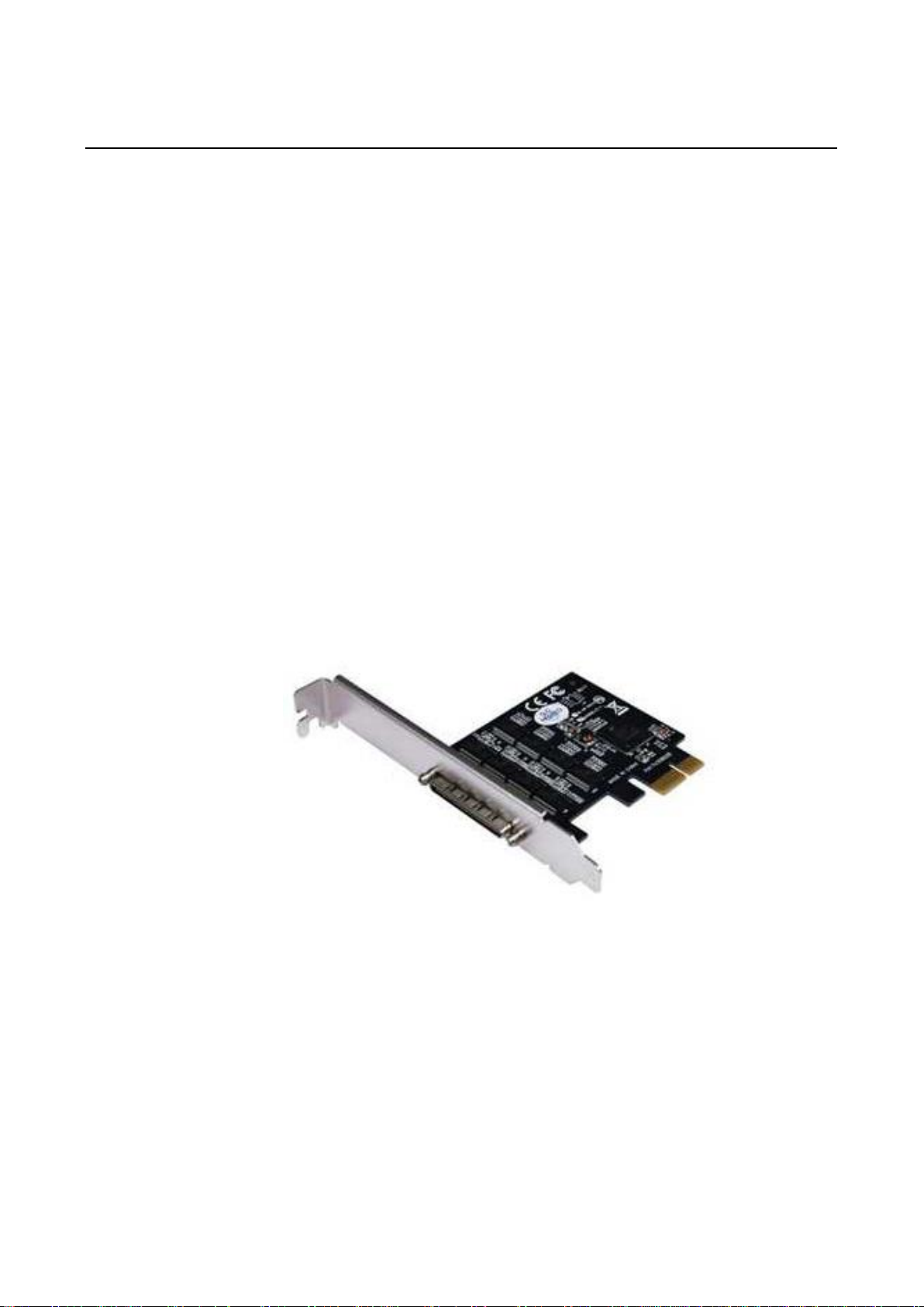
1.1 Module Physical Features
1.2 System Requirements
Windows® XP/Vista/7/8/8.1 (32/64 bit), Linux 2.6.31 or later
One available PCI Express x1, x4, x8 or x16 slot
1.3 Package contents
1 x 8-Port RS-232 PCIe Card
1 x Driver CD
1 x Fan Out Cable
1 x Spare low profile bracket
5
If any of the above items is damaged or missing, contact your retailer.
Chapter 2: Installation
2.1 Hardware Installation
I. Turn off the power to your computer.
II. Unplug the power cord and remove your computer’s cover.
III. Remove the slot bracket from an available PCIe slot.
IV. To install the card, carefully align the card’s bus connector with the selected PCIe slot on the motherboard. Push
the board down firmly.
V. Replace the slot bracket’s holding screw to secure the card.
VI. Secure the computer cover and reconnect the power cord.
2.2 Pin Assignment
The 8-ports RS-232 PCIe Card has a female SCSI VHDCI68 connector on the board. In this section, we give
the on-board connector’s pin assignments to facilitate making your own connection cable, and the male DB9
device-side pin assignments for the fan out cable.
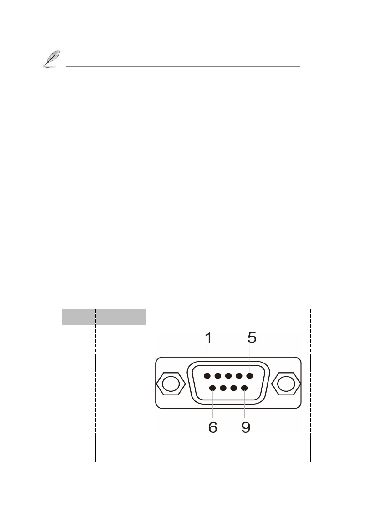
Male DB9 Connector: Device-side Pin Assignments:
Pin
Description
1
DCD
2
RxD
3
TxD
4
DTR
5
GND
6
DSR
7
RTS
8
CTS
9
RI

Female SCSI VHDCI68: Board-side Pin Assignments:
Pin
Signal
Pin
Signal
1
RxD7
35
RxD8
2
CTS7
36
CTS8
3
RI7
37
RI8
4
RTS7
38
RTS8
5
DCD7
39
DCD8
6
DTR7
40
DTR8
7
DSR7
41
DSR8
8
TxD7
42
TxD8
9
GND
43
GND
10
TxD5
44
TxD6
11
DSR5
45
DSR6
12
DTR5
46
DTR6
13
DCD5
47
DCD6
14
RTS5
48
RTS6
15
RI5
49
RI6
16
CTS5
50
CTS6
17
RxD5
51
RxD6
18
RxD3
52
RxD4
19
CTS3
53
CTS4
20
RI3
54
RI4
21
RTS3
55
RTS4
22
DCD3
56
DCD4
23
DTR3
57
DTR4
7
24
DSR3
58
DSR4
25
TxD3
59
TxD4
26
GND
60
GND
27
TxD1
61
TxD2
28
DSR1
62
DSR2
29
DTR1
63
DTR2
30
DCD1
64
DCD2
31
RTS1
65
RTS2
32
RI1
66
RI2
33
CTS1
67
CTS2
34
RxD1
68
RxD2
2.3 Driver Installation
Installation for Windows
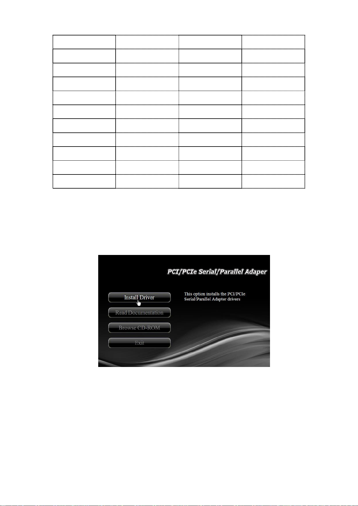
1. Insert the provided CD into your disk drive. The CD-ROM will start automatically. The following screen will show up
and please click “Install Driver”.
*Note: Actual image may vary
Note: If the install program doesn’t run automatically, please locate and double-click on the Autorun.exe file in the
CD to launch the install program.

2. Please click “PCI Express Card”.
*Note: Actual image may vary
3. Please click “Windows”to start the installation.
4. Follow the instructions on screen to install the driver.
Installation for Linux
1. Insert the provided CD into your CD-ROM drive.
2. Extract the compressed driver source file to a certain directory by the following command: (Please copy the driver
file “xr17v25x_35x-lnx3.x.x-pak.zip” from the CD folder “.\Driver\PCIe\PLX&EXAR\EXAR\Linux” to a certain folder on
hard drive)
# unzip xr17v25x_35x-lnx3.x.x-pak.zip
3. Now, the driver source files should be extracted under the current directory. Executing the following command to
compile the driver:
# make
4. If the compilation is well, the xr17v35x.ko will be created under the current directory.
5. Then executing the following command to activate the module driver:
# insmod xr17v35x.ko
Table of contents
Other Gbord PCI Card manuals


