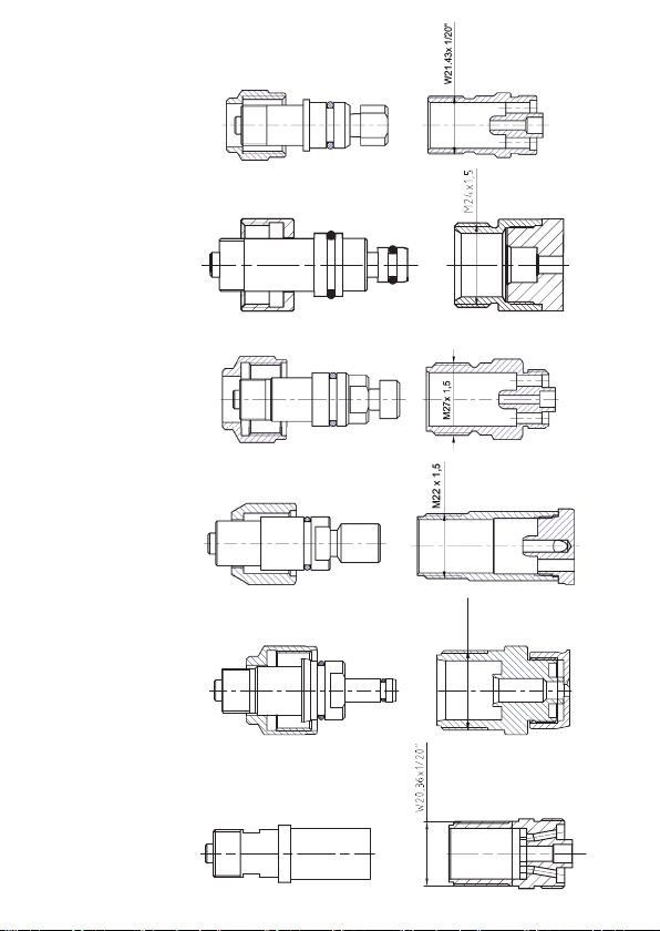
GCE KOMBI 17 User manual

GCE CUTTING & WELDING TECHNOLOGIES
KOMBI 17, 18, 20, CZ, 2001, RK20
CUTTING AND WELDING SET
HANDSCHNEIDBRENNER
SVÁŘECÍ A ŘEZACÍ SOUPRAVA
ZVÁRACIA A REZACIA SÚPRAVA
ZESTAW DO SPAWANIA I CIĘCIA
HEGESZTŐ ÉS LÁNGVÁGÓ SZETT
COFFRET SOUDAGECOUPAGE
SET DI TAGLIO E SALDATURA
KIT DE CORTE Y SOLDADURA
INSTRUCTION FOR USE
BEDIENUNGSANLEITUNG
NÁVOD K POUŽITÍ
NÁVOD NA OBSLUHU
INSTRUKCJA OBSŁUGI
HASZNÁLATI ÚTMUTATÓ
ИНСТРУКЦИЯ ПО ЭКСПЛУАТАЦИИ
NOTICE D´UTILISATION
ISTRUZIONI PER L’USO
INSTRUCCIONES DE USO
FR
IT
ES
SK
PL
HU
RU
CS
DE
EN


2001
RK20
KOMBI 17
KOMBI 18
KOMBI 20
KOMBI CZ
U7-CZ
22
M x 1,5
M27 x 1,5
U7-2001

Fig. 1: Schematic picture
1. Inlet connection for fuel gas
2. Inlet connection for oxygen
3. Red label for fuel gas valve
4. Blue label for oxygen valve
5. Bushing
6. Nut
7. Gasket for attachment
8. Mixer
9. Neck (Connecting tube)
10. Heating nozzle
11. Welding nozzle
12. Welding nozzle flexible
13. Valve for the heating oxygen
14. Lever or valve for the cutting oxygen
15. Head of the torch
16. Nozzle nut
17. Propane cutting nozzle - nozzle mix type
18. Acetylene cutting nozzle - nozzle mix type
19. Acetylene cutting nozzle - injector type
20. Propane cutting nozzle - injector type
Fig. 1: Schematic picture
U7CZ/HUU7GERMAN
8
7
12
8
7
910
8
7
911
8
7
11
BC D
21
4
5
3
6
4
3
1. Inlet connection for fuel gas
2. Inlet connection for oxygen
3. Red label for fuel gas valve
4. Blue label for oxygen valve
5. Bushing
6. Nut
7. Gasket for attachment
8. Mixer
9. Neck (Connecting tube)
10. Heating nozzle
11. Welding nozzle
12. Welding nozzle flexible
13. Valve for the heating oxygen
14. Lever or valve for the cutting oxygen
15. Head of the torch
16. Nozzle nut
17. Propane cutting nozzle - nozzle mix type
18. Acetylene cutting nozzle - nozzle mix type
19. Acetylene cutting nozzle - injector type
20. Propane cutting nozzle - injector type
Fig. 1: Schematic picture
U7CZ/HUU7GERMAN
A

Fig. 1: Schematic picture
14
13
15 16
14
15
bar
3-10
R
A
2,5-3,5
bar
3-10
R
A
2,5-3,5
Fig. 1: Schematic picture
1. Inlet connection for fuel gas
2. Inlet connection for oxygen
3. Red label for fuel gas valve
4. Blue label for oxygen valve
5. Bushing
6. Nut
7. Gasket for attachment
8. Mixer
9. Neck (Connecting tube)
10. Heating nozzle
11. Welding nozzle
12. Welding nozzle flexible
13. Valve for the heating oxygen
14. Lever or valve for the cutting oxygen
15. Head of the torch
16. Nozzle nut
17. Propane cutting nozzle - nozzle mix type
18. Acetylene cutting nozzle - nozzle mix type
19. Acetylene cutting nozzle - injector type
20. Propane cutting nozzle - injector type
21. Acetylene cutting nozzle - injector type threaded (inner /outer)
22. Propane cutting nozzle - injector type threaded (inner /outer)
A
R
3-100
mm
P
R
3-100
mm
14
13
7
15
bar
3-10
R
A
2,5-3,5
bar
3-10
R
A
2,5-3,5
Fig. 1: Schematic picture
1. Inlet connection for fuel gas
2. Inlet connection for oxygen
3. Red label for fuel gas valve
4. Blue label for oxygen valve
5. Bushing
6. Nut
7. Gasket for attachment
8. Mixer
9. Neck (Connecting tube)
10. Heating nozzle
11. Welding nozzle
12. Welding nozzle flexible
13. Valve for the heating oxygen
14. Lever or valve for the cutting oxygen
15. Head of the torch
16. Nozzle nut
17. Propane cutting nozzle - nozzle mix type
18. Acetylene cutting nozzle - nozzle mix type
19. Acetylene cutting nozzle - injector type
20. Propane cutting nozzle - injector type
21. Acetylene cutting nozzle - injector type threaded (inner /outer)
22. Propane cutting nozzle - injector type threaded (inner /outer)
A
R
3-100
mm
P
R
3-100
mm
14
13
15 16
bar
3-10
R
A
2,5-3,5
bar
3-10
R
A
2,5-3,5
Fig. 1: Schematic picture
1. Inlet connection for fuel gas
2. Inlet connection for oxygen
3. Red label for fuel gas valve
4. Blue label for oxygen valve
5. Bushing
6. Nut
7. Gasket for attachment
8. Mixer
9. Neck (Connecting tube)
10. Heating nozzle
11. Welding nozzle
12. Welding nozzle flexible
13. Valve for the heating oxygen
14. Lever or valve for the cutting oxygen
15. Head of the torch
16. Nozzle nut
17. Propane cutting nozzle - nozzle mix type
18. Acetylene cutting nozzle - nozzle mix type
19. Acetylene cutting nozzle - injector type
20. Propane cutting nozzle - injector type
21. Acetylene cutting nozzle - injector type threaded (inner /outer)
22. Propane cutting nozzle - injector type threaded (inner /outer)
A
R
3-100
mm
P
R
3-100
mm
bar
3-10
R
A
2,5-3,5
bar
3-10
R
A
2,5-3,5
Fig. 1: Schematic picture
1. Inlet connection for fuel gas
2. Inlet connection for oxygen
3. Red label for fuel gas valve
4. Blue label for oxygen valve
5. Bushing
6. Nut
7. Gasket for attachment
8. Mixer
9. Neck (Connecting tube)
10. Heating nozzle
11. Welding nozzle
12. Welding nozzle flexible
13. Valve for the heating oxygen
14. Lever or valve for the cutting oxygen
15. Head of the torch
16. Nozzle nut
17. Propane cutting nozzle - nozzle mix type
18. Acetylene cutting nozzle - nozzle mix type
19. Acetylene cutting nozzle - injector type
20. Propane cutting nozzle - injector type
21. Acetylene cutting nozzle - injector type threaded (inner /outer)
22. Propane cutting nozzle - injector type threaded (inner /outer)
A
R
3-100
mm
P
R
3-100
mm
18
17
19 20
22
22 21
21

EN
A. Shank
B. Flexible welding attachment
C. Heating attachment
D. Welding attachment
E. Cutting attachment - injector type
F. Cutting attachment - nozzle mix type
1. Inlet connection for fuel gas
2. Inlet connection for oxygen
3. Fuel gas valve
4. Oxygen valve
5. Outlet connection for attachments
6. Quick coupling
7. Gasket for attachments
8. Mixer
9. Neck (connecting tube)
10. Heating nozzle
11. Welding nozzle
12. Welding nozzle flexible
13. Valve for the heating oxygen
14. Lever or valve for cutting oxygen
15. Head of the torch
16. Nozzle nut
17. Propane cutting nozzle - nozzle mix type
18. Acetylene cutting nozzle -nozzle mix type
19. Acetylene cutting nozzle - injector type
20. Propane cutting nozzle - injector type
21. Acetylene cutting nozzle - injector type threaded (inner / outer)
22. Propane cutting nozzle - injector type threaded (inner / outer)
DE
A. Gri
B. Flexibler Rohrschweißeinsatz
C. Anwärmeinsatz
D. Schweißeinsatz
E. Schneideinsatz - Injektortyp
F. Schneideinsatz - in der Mischdüse
1. Eingangsanschluss für Brenngas
2. Eingangsanschluss für Sauersto
3. Brenngasventil
4. Sauerstoventil
5. Ausgangsanschluss für Einsätze
6. Anschlussmutter für Einsätze
7. Dichtung für Einsätze
8. Mischventil
9. Anschlussrohr
10. Heizdüse
11. Schweißdüse
12. Schweißdüse flexibel
13. Heizsauerstoventil
14. Hebel oder Ventil für Schneidsauersto
15. Brennerkopf
16. Düsenmutter
17. Propanschneiddüse
(für den Aufsatz mit Mischvorgang in der Düse)
18. Azetylenschneiddüse
(für den Aufsatz mit Mischvorgang in der Düse)
19. Azetylenschneiddüse
(für den Aufsatz mit Injektor-Mischvorgang)
20. Propanschneiddüse
(für den Aufsatz mit Injektor-Mischvorgang)
21. Acetylen-Schneiddüse - Injektortyp mit Gewinde (innen/außen)
22. Propanschneiddüse - Injektortyp mit Gewinde (innen/außen)
CS
A. Rukojeť
B. Flexibilní svařovací nástavec
C. Nahřívací nástavec
D. Svařovací nástavec
E. Řezací nástavec - injektorový typ
F. Řezací nástavec - se směšováním v hubici
1. Vstupní připojení pro hořlavý plyn
2. Vstupní připojení pro kyslík
3. Ventilek pro hořlavý plyn
4. Ventilek pro kyslík
5. Výstupní připojení pro nástavce
6. Připojovací matice pro nástavce
7. Těsnění pro nástavce
8. Směšovač
9. Připojovací trubka
10. Nahřívací hubice
11. Svařovací hubice
12. Svařovací hubice flexibilní
13. Ventilek pro nahřívací kyslík
14. Páka nebo ventilek pro řezací kyslík
15. Hlava řezacího nástavce
16. Matice hubice
17. Propanová řezací hubice (pro nástavec se směšováním v hubici)
18. Acetylenová řezací hubice (pro nástavec se směšováním v hubici)
19. Acetylenová řezací hubice (pro nástavec s injekčním směšováním)
20. Propanová řezací hubice (pro nástavec s injekčním směšováním)
21. Acetylenová řezací hubice (vnitřní/ vnější) se závitovým připojením
proinjektorové řezací hořáky
22. Propanová řezací hubice (vnitřní/ vnější) se závitovým připojením pro
injektorové řezací hořáky
SK
A. Rukoväť
B. Flexibilný zvárací nadstavec
C. Nahrievací nadstavec
D. Zvárací nadstavec
E. Rezací nadstavec – injektorový typ
F. Rezací nadstavec – so zmiešavaním v hubici
1. Vstupné pripojenie na horľavý plyn
2. Vstupné pripojenie na kyslík
3. Ventilček na horľavý plyn
4. Ventilček na kyslík
5. Výstupné pripojenie na nadstavce
6. Pripájacie matice na nadstavce
7. Tesnenie na nadstavce
8. Zmiešavač
9. Pripájacia rúrka
10. Nahrievacia hubica
11. Zváracia hubica
12. Zváracia hubica flexibilná
13. Ventilček na nahrievací kyslík
14. Páka alebo ventilček na rezací kyslík
15. Hlava rezacieho nadstavca
16. Matica hubice
17. Propánová rezacia hubica
(na nadstavec so zmiešavaním v hubici)
18. Acetylénová rezacia hubica
(na nadstavec so zmiešavaním v hubici)
19. Acetylénová rezacia hubica
(na nadstavec s injekčným zmiešavaním)
20. Propánová rezacia hubica (na nadstavec s injekčným zmiešavaním)
21. Acetylénová rezacia hubica (vnútorná/vonkajšia) so závitovým
pripojením k injektorovým rezacím horákom.
22. Propánová rezacia hubica (vnútorná/vonkajšia) so závitovým pripo-
jením k injektorovým rezacím horákom.

HU
A. Markolat
B. Flexibilis hegesztő toldalék
C. Hevítő toldalék
D. Hegesztő toldalék
E. Lángvágó toldalék – injektoros típus
F. Lángvágó toldalék – keverés a fúvókában
1. Égőgáz bemeneti csatlakozó
2. Oxigén bemeneti csatlakozó
3. Égőgáz szelep
4. Oxigén szelep
5. Toldalék kimeneti csatlakozó
6. Toldalék csatlakoztató anya
7. Toldalék tömítés
8. Keverőszelep
9. Csatlakozócső
10. Hevítő fúvóka
11. Hegesztő fúvóka
12. Flexibilis hevítő fúvóka
13. Hevítő gáz szelep
14. Lángvágó oxigén kar vagy szelep
15. Lángvágó toldalék fő
16. Fúvóka anya
17. Propán lángvágó fúvóka (a fúvókában történő keverés toldaléka)
18. Acetilén lángvágó fúvóka (a fúvókában történő keverés toldaléka)
19. Acetilén lángvágó fúvóka (injekciós keverés toldaléka)
20. Propán lángvágó fúvóka (injekciós keverés toldaléka)
21. Acetilén vágó fúvóka - injektoros típusú menetes (belső / külső)
22. Propán vágó fúvóka - injektoros típusú menetes (belső / külső)
PL
A. Rękojeść
B. Nasadka do spawania giętkia
C. Nasadka do grzania
D. Nasadka do spawania
E. Nasadka do cięcia - typ inżektorowy
F. Nasadka do cięcia - z dyszą mieszającą
1. Przyłącze wlotowe gazu palnego
2. Przyłącze wlotowe tlenu
3. Zaworek gazu palnego
4. Zaworek tlenu
5. Przyłącze wylotowe dla nasadek
6. Nakrętka złączna dla nasadek
7. Uszczelka dla nasadek
8. Komora mieszania
9. Rurka podłączająca
10. Dysza do grzania
11. Dysza do spawania
12. Dysza do spawania giętka
13. Zaworek do tlenu do grzania
14. Dźwignia lub zaworek dla tlenu do cięcia
15. Głowica nasadki do cięcia
16. Nakrętka dyszy
17. Dysza propanowa do cięcia (do nasadki z dyszą mieszającą)
18. Dysza acetylenowa do cięcia (do nasadki z dyszą mieszającą)
19. Dysza acetylenowa do cięcia
(do nasadki z mieszaniem inżektorowym)
20. Dysza propanowa do cięcia
(do nasadki z mieszaniem inżektorowym)
21. Dysza tnąca acetylenowa – typ inżektorowy, gwintowana
(wewnętrznie / zewnętrznie)
22. Dysza tnąca propanowa – typ inżektorowy, gwintowana
(wewnętrznie / zewnętrznie)

HU
A. Markolat
B. Flexibilis hegesztő toldalék
C. Hevítő toldalék
D. Hegesztő toldalék
E. Lángvágó toldalék – injektoros típus
F. Lángvágó toldalék – keverés a fúvókában
1. Égőgáz bemeneti csatlakozó
2. Oxigén bemeneti csatlakozó
3. Égőgáz szelep
4. Oxigén szelep
5. Toldalék kimeneti csatlakozó
6. Toldalék csatlakoztató anya
7. Toldalék tömítés
8. Keverőszelep
9. Csatlakozócső
10. Hevítő fúvóka
11. Hegesztő fúvóka
12. Flexibilis hevítő fúvóka
13. Hevítő gáz szelep
14. Lángvágó oxigén kar vagy szelep
15. Lángvágó toldalék fő
16. Fúvóka anya
17. Propán lángvágó fúvóka (a fúvókában történő keverés toldaléka)
18. Acetilén lángvágó fúvóka (a fúvókában történő keverés toldaléka)
19. Acetilén lángvágó fúvóka (injekciós keverés toldaléka)
20. Propán lángvágó fúvóka (injekciós keverés toldaléka)
21. Acetilén vágó fúvóka - injektoros típusú menetes (belső / külső)
22. Propán vágó fúvóka - injektoros típusú menetes (belső / külső)
RU
A.
B.
C.
D.
E. -
F. -
1.
2.
3.
4.
5.
6.
7.
8.
9.
10.
11.
12.
13.
14.
15.
16.
17.
18. ( )
19. ( )
20. ( )
21. ( )
22. (/
)
FR
A. Manche
B. Lance de soudage flexible
C. Lance de coupe
D. Lance de soudage
E. Lance de coupe – type injecteur
F. Lance de coupe – avec mélange dans la buse
1. Connexion d’entrée pour gaz combustible
2. Connexion d’entrée pour oxygène
3. Robinet pour gaz combustible
4. Robinet pour oxygène
5. Connexion de sortie pour lances
6. Ecrou de raccordement pour lances
7. Joints de lance
8. Mélangeur
9. Tube de connexion
10. Buse de chaue
11. Bec de soudage
12. Bec de soudage flexible
13. Robinet pour oxygène de chaue
14. Levier ou robinet pour oxygène de coupe
15. Tête de coupe
16. Écrou de bec
17. Buse de coupe propane (pour lance à mélange dans
la buse)
18. Buse de coupe acétylène (pour lance à mélange
dans la buse)
19. Buse de coupe acétylène (pour lance à injecteur)
20. Buse de coupe propane (pour lance à injecteur)
21. Buse de coupe acétylène (femelle/ mâle) avec rac-
cord fileté pour chalumeaux coupeurs à injecteur
22. Buse de coupe propane (femelle/ mâle) avec rac-
cord fileté pour chalumeaux coupeurs à injecteur

ES
A. Mango
B. BAccesorio de soldadura flexible
C. Accesorio de calentamiento
D. Accesorio de soldadura
E. Accesorio de corte - tipo inyector
F. Accesorio de corte - tipo de boquilla de mezcla
1. Conexión de entrada para gas combustible
2. Conexión de entrada para oxígeno
3. Válvula de gas combustible
4. Válvula de oxígeno
5. Conexión de salida para accesorios
6. Acoplamiento rápido
7. Junta para accesorios
8. Mezclador
9. Cuello (tubo de conexión)
10. Boquilla de calentamiento
11. Boquilla de soldadura
12. Boquilla de soldadura flexible
13. Válvula para calentar el oxígeno
14. Palanca o válvula para cortar oxígeno
15. Cabezal de antorcha
16. Tuerca de la boquilla
17. Boquilla de corte de propano - boquilla de tipo mezcla
18. Boquilla de corte de acetileno - boquilla de tipo mezcla
19. Boquilla de corte de acetileno - tipo inyector
20. Boquilla de corte de propano - tipo inyector
21. Boquilla de corte de acetileno - tipo inyector roscado (interior / exterior)
22. Boquilla de corte de propano - tipo inyector roscado (interior / exterior)
IT
A. Maniglia
B. Accessorio per la saldatura flessibile
C. Accessorio per il riscaldamento
D. Accessorio per la saldatura
E. Accessorio per il taglio - tipo iniettore
F. Accessorio per il taglio - tipo mix di ugelli
1. Raccordo d’ingresso per il gas combustibile
2. Raccordo d’ingresso per l’ossigeno
3. Valvola del gas combustibile
4. Valvola dell’ossigeno
5. Raccordo di uscita per gli accessori
6. Accoppiamento rapido
7. Guarnizione per gli accessori
8. Miscelatore
9. Tubo di collegamento
10. Ugello di riscaldamento
11. Ugello di saldatura
12. Ugello di saldatura flessibile
13. Valvola per l’ossigeno da riscaldamento
14. Leva o valvola per tagliare l’ossigeno
15. Testa della torcia
16. Dado dell’ugello
17. Ugello di taglio a propano - tipo mix di ugelli
18. Ugello di taglio ad acetilene - tipo mix di ugelli
19. Ugello di taglio ad acetilene - tipo iniettore
20. Ugello di taglio a propano - tipo iniettore
21. Ugello di taglio ad acetilene - tipo iniettore filettato (interno / esterno)
22. Ugello di taglio a propano - tipo iniettore filettato (interno / esterno)

Fig. 2: Marking
A
3-10
mm
2-2,5
bar
A
3-100
RHONA
bar
3-10
R
A
2,5-3,5
3-100
mm
A
R
LOGO
0,5 - 1mm
A
PNME
PNME
ANME
A
NO 1
P
P-HP 433
NO 2
5A
800L
3,0 bar
1-50 mm
1-5 bar
HP433 3-10 mm
1,5-3 bar HA 411
3-8mm
1.5-2.0 BAR
5-12 mm
3/64
5-12 mm
5-12 mm
3/64
Fig. 2: Marking
11
9
11
12
7
8
1
10
9
8
4
1
3
534
6
5
534
12
11
9
7
A
3-10
mm
2-2,5
bar
A
3-100
RHONA
bar
3-10
R
A
2,5-3,5
3-100
mm
A
R
LOGO
0,5 - 1mm
A
PNME
PNME
ANME
A
NO 1
P
P-HP 433
NO 2
5A
800L
3,0 bar
1-50 mm
1-5 bar
HP433 3-10 mm
1,5-3 bar HA 411
3-8mm
1.5-2.0 BAR
5-12 mm
3/64
5-12 mm
5-12 mm
3/64
Fig. 2: Marking
1
10
9
A
3-10
mm
2-2,5
bar
A
3-100
RHONA
bar
3-10
R
A
2,5-3,5
3-100
mm
A
R
LOGO
0,5 - 1mm
A
PNME
PNME
ANME
A
NO 1
P
P-HP 433
NO 2
5A
800L
3,0 bar
1-50 mm
1-5 bar
HP433 3-10 mm
1,5-3 bar HA 411
3-8mm
1.5-2.0 BAR
5-12 mm
3/64
5-12 mm
5-12 mm
3/64
Fig. 2: Marking
1
3
4
2
A
3-10
mm
2-2,5
bar
A
3-100
RHONA
bar
3-10
R
A
2,5-3,5
3-100
mm
A
R
LOGO
0,5 - 1mm
A
PNME
PNME
ANME
A
NO 1
P
P-HP 433
NO 2
5A
800L
3,0 bar
1-50 mm
1-5 bar
HP433 3-10 mm
1,5-3 bar HA 411
3-8mm
1.5-2.0 BAR
5-12 mm
3/64
5-12 mm
5-12 mm
3/64
Fig. 2: Marking
5
3
4
1
2
3
4
5
3
4
5
6
2
3
8
ES
A. Mango
B. BAccesorio de soldadura flexible
C. Accesorio de calentamiento
D. Accesorio de soldadura
E. Accesorio de corte - tipo inyector
F. Accesorio de corte - tipo de boquilla de mezcla
1. Conexión de entrada para gas combustible
2. Conexión de entrada para oxígeno
3. Válvula de gas combustible
4. Válvula de oxígeno
5. Conexión de salida para accesorios
6. Acoplamiento rápido
7. Junta para accesorios
8. Mezclador
9. Cuello (tubo de conexión)
10. Boquilla de calentamiento
11. Boquilla de soldadura
12. Boquilla de soldadura flexible
13. Válvula para calentar el oxígeno
14. Palanca o válvula para cortar oxígeno
15. Cabezal de antorcha
16. Tuerca de la boquilla
17. Boquilla de corte de propano - boquilla de tipo mezcla
18. Boquilla de corte de acetileno - boquilla de tipo mezcla
19. Boquilla de corte de acetileno - tipo inyector
20. Boquilla de corte de propano - tipo inyector
21. Boquilla de corte de acetileno - tipo inyector roscado (interior / exterior)
22. Boquilla de corte de propano - tipo inyector roscado (interior / exterior)

EN
1. Gas
2. Name of the nozzle
3. Cutting or welding thickness
4. Oxygen pressure
5. Size
6. Flow
7. Red label for fuel gas
8. Blue label for oxygen
9. Name of the product
10. Type of the mixing
11. Standard
12. Name of the producer
DE
1. Gas
2. Bezeichnung der Düse
3. Schneid- oder Schweißdicke für
Düsen
4. Sauerstodruck
5. Größe
6. Durchfluss
7. Rotes Schild für Brenngas
8. Blaues Schild für Sauersto
9. Produktname
10. Mischungstyp
11. Norm
12. Name des Herstellers
CS
1. Plyn
2. Název hubice
3. Řezací či svařovací tloušťka pro
hubice
4. Tlak kyslíku
5. Velikost
6. Průtok
7. Červený štítek pro hořlavý plyn
8. Modrý štítek pro kyslík
9. Název výrobku
10. Typ směšování
11. Norma
12. Název (jméno) výrobce
SK
1. Plyn
2. Názov hubice
3. Rezacia či zváracia hrúbka pre hubice
4. Tlak kyslíka
5. Veľkosť
6. Prietok
7. Červený štítok na horľavý plyn
8. Modrý štítok na kyslík
9. Názov výrobku
10. Typ zmiešavania
11. Norma
12. Názov (meno) výrobcu
PL
1. Gas
2. Name of the nozzle
3. Cutting or welding thickness
4. Oxygen pressure
5. Size
6. Flow
7. Red label for fuel gas
8. Blue label for oxygen
9. Name of the product
10. Type of the mixing
11. Standard
12. Name of the producer
HU
1. Gáz
2. Fúvóka neve
3. Fúvóka vágási vagy hegesztési vas-
tagsága
4. Oxigénnyomás
5. Méret
6. Térfogatáram
7. Piros címke az égőgáz számára
8. Kék címke az oxigén számára
9. Termék neve
10. Keverés típusa
11. Szabvány
12. Gyártó neve

RU
1.
2.
3.
4.
5.
6.
7.
8.
9.
10.
11.
12. ()
FR
1. Gaz
2. Nom du bec
3. Épaisseur de coupe ou de soudage
pour becs
4. Pression d’oxygène
5. Taille
6. Début
7. Etiquette rouge pour gaz combustible
8. Étiquette bleue pour oxygène
9. Désignation du produit
10. Type de mélange
11. Norme
12. Nom du fabricant
IT
1. Gas
2. Nome dell’ugello
3. Spessore di taglio o saldatura
4. Pressione dell’ossigeno
5. Dimensione
6. Flusso
7. Etichetta rossa per il gas combustibile
8. Etichetta blu per l’ossigeno
9. Nome del prodotto
10. Tipo di miscelazione
11. Standard
12. Nome del produttore
ES
1. Gas
2. Nombre de la boquilla
3. Grosor de corte o soldadura
4. Presión del oxígeno
5. Tamaño
6. Caudal
7. Etiqueta roja para gas combustible
8. Etiqueta azul para oxígeno
9. Nombre del producto
10. Tipo de la mezcla
11. Estándar
12. Nombre del fabricante

14/64
EN
1. FOREWORD
The product complies with the essential requirements of standards:
• ISO EN 5172 - Gas welding equipment - Blowpipes for gas welding, heating
and cutting – Specifications and tests
• EN 560 – Gas welding equipment - Hose connections for equipment for
welding, cutting and allied processes
• EN 1256 Gas welding equipment -Specification for hose assemblies for
equipment for welding, cutting and allied processes
• EN ISO 3821 Gas welding equipment - Rubber hoses for welding, cutting
and allied processes
• ISO 5175-1 - Gas welding equipment. Safety devices. Incorporating a flame
(flashback)arrestor.
• ISO 5175-2 - Gas welding equipment. Safety devices. Not incorporating a
flame (flashback) arrestor
• ISO 5175 - Equipment used in gas welding, cutting and allied processes
- Safety devices for fuel gases and oxygen or compressed air -- General
specifications, requirements and tests
2. INTENDED USE
Welding and Cutting set KOMBI 17, 18, 20, 2001,CZ, RK20 is intended for use with
oxygen and fuel gases.
3. SAFETY REQUIREMENTS
All indications showing this exclamation mark are important safety instruc-
tions.
• Installation and operation of the equipment must be only done by qualified
personnel in accordance with local directions, rules and standards.
• The product should be used at temperature from -20°C to +60°C.
• Use only nozzles that are recommended by producer of this cutter (see App.
Nr. 1).
• Use safety devices that are recommended by producer or required by na-
tional standards in each country.
• For safety reasons all shut-o valves should to be opened slowly and
smoothly.
• Check that all ventilation grills are free from obstruction and that the extrac-
tion system (when installed) is functioning correctly.
• National laws, rules and regulations for compressed gases, accident pre-
vention and environmental protection must be observed.
Keep the product and its associated equipment away from: oil or grease - al-
ways wash your hands prior to handling the product or the cylinder; water;
dust; flammable substance and materials.
ENGLISH
INSTRUCTION FOR USE: CUTTING AND WELDING SET

15/64
EN
Never use product or its associated Equipment if damaged or contaminated.
Ensure only the correct gas supply is connected to the product. Connection
of the incorrect gas supply could lead to explosion or fire, causing personnel
injury and damage to property.
The product must not, under any circumstances be modified.
4. PRODUCT DESCRIPTION
Welding and cutting set KOMBI 17, 18, 20, 2001,CZ, RK20 is intended for use with
oxygen and flammable gas.
4.1. SCHEMATIC PICTURE OF THE CUTTING AND WELDING SET
KOMBI 17, 18, 20, 2001,CZ, RK20
See Fig. 1: Schematic picture
4.2. MARKING
See Fig. 2: Marking
TYPE OF GAS WW CODE COLOUR CODING
Acetylene A RED
Oxygen O BLUE
LPG (incl. propane, butane and propylene) P RED
Fuel gas F RED
Tab. 1: Types of gas
MARKING DESCRIPTION
injector type of mixing with resistant
against to flashback
mixing without injection eect
injector type of mixing
Tab. 2: Type of mixing

16/64
EN
5. OPERATION
5.1. CONNECTING THE SHANK
• Connect the shank to the cylinder regulators or with a central gas supply to
the supply points with approved hoses. Secure the connection with hose
clamps.
• Check the gas tightness by soapy water or detection fluid.
5.2. LIGHTNING AND REGULATING OF THE WELDING, HEATING
AND CUTTING ATTACHMENTS
5.2.1. WELDING, BRAZING AND HEATING
NOTE: This torch operates on the injector principle. The instructions below
should therefore be followed carefully.
1. Check the sealing washer (7) on the inlet connection of the attachment for
damage.
2. Fit an appropriate welding or heating attachment with a nozzle into the
shank.
3. Close the oxygen valve (4) and the fuel-gas valve (3).
4. Set recommended working pressures by means of the adjusting screw on
the regulators.
5. Purge the hose briefly with gas by opening the oxygen valve (4). Long hos-
es and/or small cutting nozzles require somewhat longer purges. Close the
oxygen valve (4).
6. Open the fuel-gas valve (3) and purge as above. Maintain sucient fuel-gas
flow for proper purging. Close the fuel-gas valve (3).
7. Open valve for oxygen (4) a little and than for the fuel-gas valve (3) a little bit
more.
8. Light the gas mixture in front of the welding or heating nozzle.
9. The heating flame can be adjusted by means of the oxygen valve (4) and the
fuel-gas valve (3).
10. The device is now ready for use.
5.2.2. CUTTING
NOTE: Cutting attachments operates with both system of the mixing. Check
the previous chapter. The instructions bellow should therefore be followed
carefully.
1. Check the sealing washer (7) on the inlet connection of the attachment for
damage.
2. Fit a cutting attachment into the shank.
3. Fit an appropriate cutting nozzle
4. Close the oxygen valve (4) and the fuel-gas valve (3). Release the lever or
close the cutting oxygen valve (14).
5. Fully open valve for heating oxygen on the cutting attachment (13).
6. Set recommended working pressures by means of the adjusting screw on
the regulators.
7. Purge the hose briefly with gas by opening the oxygen valve (4). Long
hoses and/or small cutting nozzles require somewhat longer purges. Close
the oxygen valve (4) and the heating oxygen valve (13).

17/64
EN
8. Open the fuel-gas valve (3) and purge as above. Maintain sucient fu-
el-gas flow for proper purging. Close the fuel-gas valve (3).
9. Open the oxygen valve (4) fully, heating oxygen valve (13) a little and
fuel-gas valve (3) little bit more.
10. Light the gas mixture in front of the nozzle .
11. Open the cutting-oxygen by pressing the lever or opening cutting oxygen
valve (14). Adjust the oxygen pressure by means of the adjusting screw on
the regulator or the supply point.
12. Once the cutting oxygen is flowing, the heating flames can be adjusted by
means of the fuel-gas valve (3) and the heating oxygen valve (13)
13. The device is now ready for use.
5.3. EXTINGUISHING THE FLAME
1. Release the lever of the valve or closed the cutting oxygen valve for the
cutting oxygen (14).*
2. Slowly close the valve for fuel gas (3) and after that valve for heating oxy-
gen(4).
3. Closed the valve for heating oxygen (13) on the cutting attachment. *
*(Cutting set only)
6. MAINTENANCE
Keep the torch clean. Do not lubricate any of the parts. Oil or grease can cause
an explosion when in contact with oxygen.
• The holes in the cutting nozzle should be cleaned when necessary with
appropriate cleaning needles or with KR21 chemical cleaner. Do not use
drill bits, steel wire or similar objects for cleaning, as the channels inside the
nozzle will be damaged.
• Proper flames and an even flow of cutting oxygen cannot be obtained un-
less the edges of the nozzle holes are sharp.
• If the outlet end of the welding or cutting nozzle is damaged, it may be
repaired by polishing perpendicularly with a fine emery cloth laid on a flat
surface.
• If a valve turns too easily or too stiy, tighten or loosen respectively the
packing nut with the spanner supplied. Obtain help from a service engineer
if repairs are necessary.
6.1. REPAIRS
Repairs must be done by authorized personnel only.
7. LIFETIME AND WASTE MANAGEMENT
Life time of the product is 5 years.
At the end of the product’s life time, the product must be withdrawn from service.
The owner of the device shall prevent the reuse of the product and handle
the product in compliance with “Directive of European Parliament and Council
2008/98/EC on waste“.

18/64
EN
In accordance to Article 33 of REACH GCE, s.r.o. as responsible manufacturer
shall inform all customers if materials containing 0.1% or more of substances
included in the list of Substance of Very High Concern (SVHC). The most com-
monly used brass alloys used for bodies and other brass components contain
2-3% of lead (Pb), EC no. 231-468-6, CAS no. 7439-92-1. The lead will not be
released to the gas or surrounding environment during normal use. After end
of life the product shall be scrapped by an authorized metal recycler to ensure
ecient material handling with minimal impact to environment and health. To
date we have no information that indicates that other materials containing SVHC
of concentrations exceeding 0.1% are included in any GCE product.
8. WARRANTY
The Standard Warranty period is two years from date of receipt by the GCE
Customer (or if this is not known 2 years from time of the product manufacture
shown on the product).
The standard warranty is only valid for products handled according to Instruction
for use (IFU) and general industry good practice and standards.
APPENDIX:
Nr. 1 - Cutting table
MANUFACTURER:
GCE, s.ro. Tel : +420 569 661 111
Zizkova 381 Fax : +420 569 661 602
583 01 Chotebor http://www.gcegroup.com
Czech Republic © GCE, s.ro.

19/64
DE
1. VORWORT
Dieses Produkt erfüllt die einschlägigen Standards:
• EN ISO 5172 - Schweißgeräte Ausrüstung, Geräte zum Schweißen, Schnei-
den und Anwärmen, Spezifikationen und Tests
• EN 560 – Schweißgeräte Ausrüstung, Schlauchverbindungen zum Schwei-
ßen, Schneiden und verwandte Verfahren
• EN 1256 - Gasschweißgeräte - Festlegungen für Schlauchleitungen für Aus-
rüstungen für Schweißen, Schneiden und verwandte Prozesse
• EN 3821 - Gasschweißgeräte - Gummischläuche für Schweißen, Schneiden
und verwandte Prozesse
• ISO 5175-1 - Gasschweißgeräte - Sicherheitseinrichtungen - Teil 1: Mit integ-
rierter Flammensperre
• ISO 5175-2 - Gasschweißgeräte - Sicherheitseinrichtungen - Teil 2: Ohne
integrierte Flammensperre
• ISO 5175 - Einrichtungen für Schweißen, Schneiden und verwandte Verfah-
ren; Sicherheitseinrichtungen für Brenngase und Sauersto oder Druckluft;
Allgemeine Festlegungen, Anforderungen und Prüfungen
Lesen Sie bitte diese Anleitung vor dem Anschließen bzw. Gebrauch. Folgen
Sie immer den Anweisungen. Das Produkt sollte ausschließlich zum in der An-
leitung beschriebenen Zweck verwendet werden.
2. BESTIMMUNGSGEMÄSSER GEBRAUCH
Der Handschneidbrenner KOMBI 17, 18, 20, 2001,CZ, RK20 ist für die Anwen-
dung mit Sauersto und brennbaren Gasen bestimmt.
3. SICHERHEITSHINWEISE
Alle mit diesem Zeichen gekennzeichneten Angaben gelten als spezielle
Sicherheitshinweise.
• Die Installation bzw. das Verwenden des Gerätes darf nur durch qualifizier-
tes Personal unter Einhaltung der landesspezifischen Gesetze, Bestimmun-
gen und Normen erfolgen.
• Das Gerät sollte innerhalb des Temperaturbereiches von -20°C bis +60°C
verwendet werden.
• Bitte verwenden Sie ausschließlich Düsen, die vom Hersteller zur Verwen-
dung angegeben bzw. empfohlen werden.
• Bitte verwenden Sie Sicherheitseinrichtungen, die vom Hersteller empfoh-
len werden bzw. den Bestimmungen und Normen des Einsatzlandes ent-
sprechen.
• Aus Sicherheitsgründen sollten alle Absperrventile langsam geönet wer-
den.
• Überprüfen Sie die richtige Funktion des Entlüftungssystems, falls vorhan-
den.
DEUTSCH
BEDIENUNGSANLEITUNG: HANDSCHNEIDBRENNER

20/64
DE
• Es sind die nationalen Gesetze, Regelungen und Vorschriften zur Unfallver-
hütung und Umweltschutz beim Einsatz von Hochdruckgasen zu beachten
DAS PRODUKT UND DIE ZUGEHÖRIGEN GERÄTE SIND FERNZUHALTEN
VON: potentiellen Brandquellen (Feuer, oenes Licht, etc.), brennbaren Ma-
terialien, Ölen oder Fetten (Vorsicht bei Anwendung von Handcreme), Wasser.
Den Schneidbrenner oder daran angeschlossene Geräte niemals im defekten
oder verunreinigten Zustand verwenden.
Überprüfen Sie, dass das Gerät mit der richtigen Gasart verbunden ist.
Der Anschluss einer falschen Gasquelle kann eine Explosion oder ein Feuer
verursachen, was Personen- und / oder Sachschäden als Folge haben kann.
Am Produkt sind keine Veränderungen oder Umbauten zulässig.
4. PRODUKTBESCHREIBUNG
Der Handschneidbrenner KOMBI 17, 18, 20, 2001,CZ, RK20 ist für die Anwen-
dung mit Sauersto und brennbarem Gas bestimmt.
4.1. SCHEMATISCHE DARSTELLUNG DES HANDSCHNEIDBREN
NERS KOMBI 17, 18, 20, 2001,CZ, RK20
Siehe Fig. 1: Schematic picture
4.2. KENNZEICHNUNG
Siehe Fig. 2: Marking
GASART CODE FARBCODIERUNG
Acetylen A ROT
Sauersto O BLAU
LPG (inkl. Propan, Butan, Propylen) P ROT
Brenngas F ROT
Tab. 1: Gasarten
CODIERUNG BESCHREIBUNG
Injektor-Mischvorgang beständig gegen
das Einbrennen
Mischvorgang ohne Injektor-Eekt
Injektor-Mischvorgang des Brenngases
Tab. 2: Mischvorgang Typ
This manual suits for next models
5
Table of contents
Languages:
Other GCE Welding System manuals