Ferve F-706 User manual
1.
2.
3.
4.
5.
6.
7.
8.
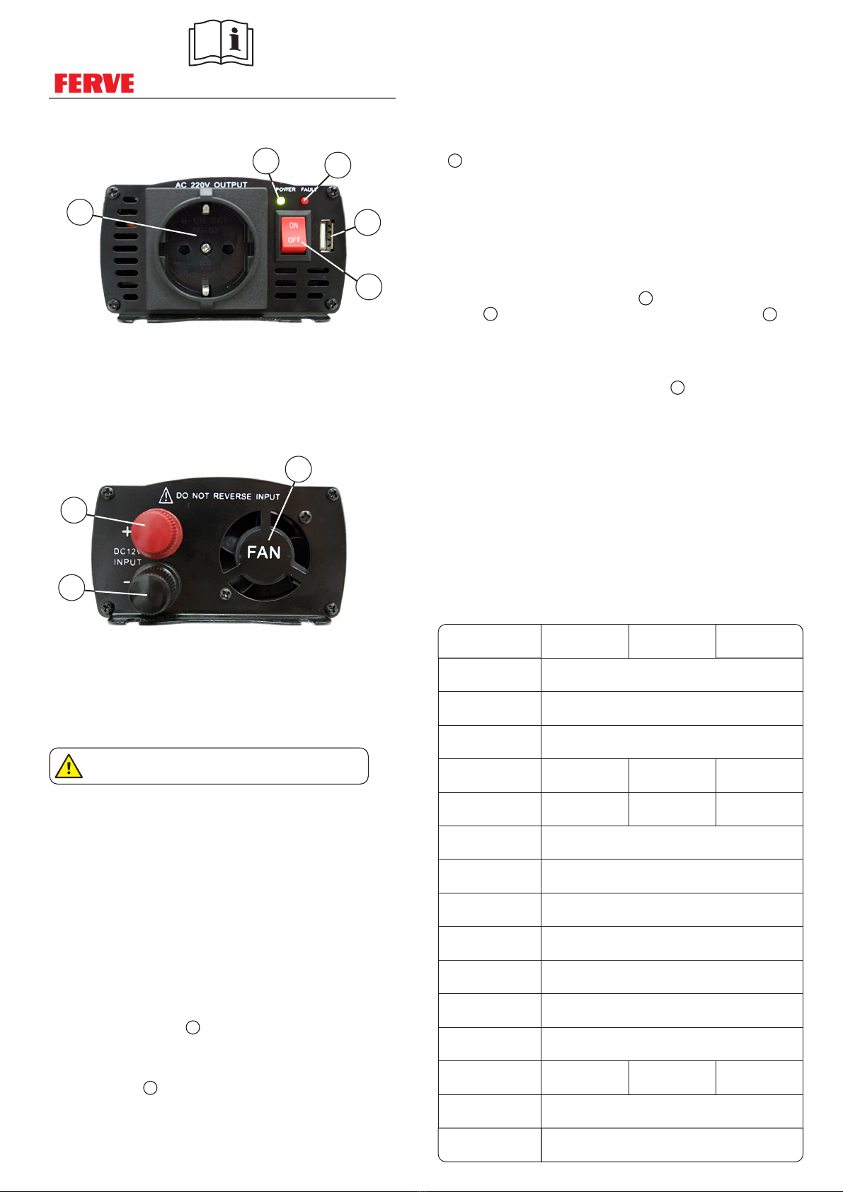
LED de encendido / verde: Se ilumina cuando el inversor tiene salida de
red.
LED de error / rojo: Se ilumina en caso de error.
Salida USB: 5 V DC, 500 mA.
Interruptor de encendido: Para poner en funcionamiento y detener el
inversor.
Salida de corriente alterna (CA) de 220-240V, 50Hz.
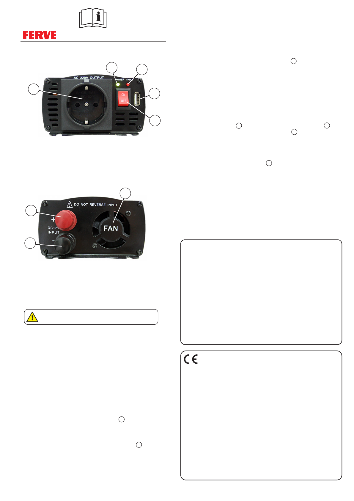
Ventilador de disipación de calor: Control inteligente, empieza a
funcionar cuando la potencia llega al 30% o la temperatura interna
alcanza los 60 ºC.
Terminal "+" / rojo: Conecte este terminal al polo positivo de la batería
(cable rojo).
Terminal "-" / negro: Conecte este terminal al polo negativo de la
batería (cable negro).
PRECAUCIONES:
•
•
•
•
•
•
•
No utilice el inversor con las manos mojadas.
Tras un largo funcionamiento, el envolvente puede alcanzar
altas temperaturas.
No introduzca piezas de metal en el inversor, puede provocar
una descarga eléctrica.
No exponga el inversor a la lluvia, la niebla o el hielo y evite el
contacto con agua o aceite.
Cuando inserte el enchufe del aparato a la salida de corriente
alterna (CA) del inversor 5 , no toque la parte metálica del
enchufe para evitar descargas eléctricas.
No conecte corriente alterna a la salida de corriente alterna
(CA) del inversor 5 . Esto destruiría el inversor y podría causar
una descarga eléctrica.
No desmonte ni abra el inversor, solo lo debe hacer un
profesional cualificado.
INSTRUCCIONES:
IMPORTANTE: Para evitar sobrecargar el inversor,
manténgalo trabajando al 85% de su potencia nominal.
1. CONEXIÓN:
Advertencia: Mantenga la conexión fija y firme en la batería
y el inversor, en caso contrario puede ser muy peligroso.
2. DESCONEXIÓN:
(
3. SALIDA USB (5V, 500mA):
•
•
•
•
•
•
•
•
Compruebe que el inversor se encuentra apagado (interruptor
4 en posición OFF).
Asegúrese de que la tensión de la batería es de 12 V.
Conecte el terminal positivo (rojo) al polo positivo de la batería
(+) y el terminal negativo (negro) al polo negativo (-) de la
batería.
Pulse el interruptor de encendido 4 (posición ON), y el LED
verde 1 se iluminará. Si suena la alarma o el LED rojo 2
se ilumina, apague el inversor y compruebe las conexiones.
Primero apague el inversor interruptor 4 en posición OFF).
Desconecte en primer lugar el terminal negativo del polo
negativo (-) de la batería y después el terminal positivo del
polo positivo (+) de la batería.
La salida USB es exclusivamente para la carga ( ,
, mp3...), no tiene la función de intercambio de datos.
Antes de cargar asegúrese de que la corriente de carga del
aparato se encuentra por debajo de la corriente del inversor.
smartphones
tablets
Si invierte la conexión, destruirá el inversor.
12
3
4
5
6
7
8
F F F-706 -708 -715• •
DESCRIPCIÓN:
Panel frontal:
Panel posterior:
Inversores de potencia de onda senoidal pura
IMPORTANTE: NO INVIERTA LA POLARIDAD,
DESTRUIRÍA EL INVERSOR.
F-706 F-708 F-715
Tensión de entrada
Input voltage
Tensión de salida
Output voltage
Salida USB
USB output
Potencia contínua
Continuous power
Pico de potencia
Peak power
Salida de onda
Output wave
Tasa de distorsión
Distortion rate
Eficiencia
Efficiency
Corriente sin carga
No load current
Alarma por tensión baja
Input under voltage alarm
Parada por tensión baja
Input under voltage
shut down
Parada por tensión alta
Input over voltage
shut down
Desconexión por
sobrecarga
Over load shut down
Temperatura de trabajo
Working temperature
Método de disipación
de calor
Heat dissipation method
DC 12V (DC 11 - 15V)
AC 220 - 240V ~ • 50 Hz
DC 5V, 500mA
600W 800W 1500W
1200W 1600W 3000W
Onda senoidal pura
Pure sine wave
< 3%
> 85%
< 0,8A
DC 10,2 - 10,8V
DC 9,2 - 9,8V
DC 15 - 16V
680 - 720W 950 - 1050W 1650 - 1700W
0 - 45 ºC
Ventilador
Fan
CARACTERÍSTICAS TÉCNICAS / TECHNICAL FEATURES
F F F-706 -708 -715• •
Pure sine wave power inverter
INSTRUCTIONS:
IMPORTANT: Keep the inverter working at 85% the nominal
power to prevent an overload.
1. CONNECTION:
Warning: Keep the connection fixed and firm in the battery
and the inverter; otherwise, it may be very dangerous.
2. DISCONNECTION:
3. USB OUTPUT (5V, 500mA):
•
•
•
•
•
•
•
•
Check that the inverter is turned off (switch 4 in the OFF
position).
Make sure the battery voltage is 12 V.
Connect the positive (red) terminal to the positive battery pole
(+) and the negative (black) terminal to the negative battery
pole (-).
Press the on switch 4 (ON position), and the green LED 1 will
light up. If the alarm sounds or the red LED 2 lights up, turn off
the inverter and check the connections.
First, turn off the inverter (switch 4 in the OFF position).
First disconnect the negative terminal from the negative battery
pole (-) and then the positive terminal from the positive battery
pole (+).
The USB output is exclusively for charging (smartphones,
tablets, mp3...). There is no data exchange function.
Before charging, make sure the device charging current is
below the inverter current.
Reversing the connection may destroy the device.
FERVE, S.A • Ctra. de Calafell, 15-25 - Apartado (P.O. Box) 7 • 43700 El Vendrell (España)
2070006-0116
DECLARACIÓN DE CONFORMIDAD
Inversores de potencia
F-706, F-708 & F-715
EN 60335-1:2012 EN 60335-2-29:2006
2006/95/CE
DECLARATION OF CONFORMITY
Power inverters
Nosotros, We, FERVE, S.A.
declaramos, bajo nuestra única responsabilidad, que los productos
a los que esta declaración se refiere,
son conformes a la siguiente norma:
según las disposiciones de la Directiva:
declare, under our sole responsibility, that the products
to which this declaration relates,
are in conformity with the following standard:
following the provisions of Directive:
El Vendrell, 2016
FERVE warrants this device against all-
defective or faulty manufacturing or parts
for a period of 24 months as of the purchase
date.This warranty excludes damages
caused by mishandling, dirt and filth,
improper connection or power, accidents
and, in general, any damages arising from
causes that are external to the device. Any
other warranty performance agreed to by
the distributor shall be the exclusive liability
of this party. Furthermore, this document
does not cover wear or damage caused to
other goods or assets as a result of a fault in
the device under warranty.This warranty is
only valid when accompanied by the
original invoice or sales receipt. This
warranty shall lose validity if the device is
handled by personnel or shops not related
to our technical service.
FERVE garantiza este aparato contra todo
defecto de fabricación o de las piezas
durante un período de 24 meses a partir de
la fecha de compra. Quedan excluidos los
daños provocados por errores de manejo,
suciedad, conexión o energía inadecuada,
accidentes y en general aquellos que
provengan de causas externas al aparato.
Cualquier otra prestación comprometida
por el distribuidor será de la exclusiva
responsabilidad del mismo. El presente
documento tampoco cubre los deterioros
ocasionados a otros bienes como
consecuencia de un defecto del aparato
garantizado. Esta garantía solamente
tendrá validez acompañada de la factura de
co m pr a o ri g in a l o el r e ci b o de l
establecimiento. Esta garantía perderá su
vigencia cuando el aparato sea manipulado
por personal o talleres ajenos a nuestros
servicios técnicos.
GARANTÍA WARRANTY
1.
2.
3.
4.
5.
6.
7.
8.
On /green LED: Lights up when the inverter is connected to the
power supply.
Error / red LED: Lights up to indicate an error.
USB Output: 5 V DC, 500 mA.
On/off switch: To turn the inverter on and off.
220-240V, 50Hz alternating current (AC) output.
Heat dissipation fan: Smart control, begins working when the power
reaches 30% or the internal temperature reaches 60º C.
"+" / red terminal: Connect this terminal to the positive battery pole
(red wire).
"-" / black terminal: Connect this terminal to the negative battery
pole (black wire).
PRECAUTIONS:
•
•
•
•
•
•
•
Do not use the inverter with wet hands.
After extended operation, the outside may become very hot.
Do not insert metal parts into the inverter; doing so could
cause electric shock.
Do not expose the inverter to rain, fog or ice and avoid contact
with water or oil.
When you insert the plug into the inverter 5 alternating
current (AC) output, do not touch the metal part of the plug.
Doing so may cause electric shock.
Do not connect alternating current to the inverter 5 alternating
current (AC) output. This would destroy the inverter and could
cause electric shock.
Do not dismantle or open the inverter; this may only be done
by a qualified professional.
6
7
8
Back panel:
IMPORTANT: DO NOT INVERT THE POLARITY;
DOING SO WILL DESTROY THE INVERTER.
12
3
4
5
DESCRIPTION:
Front panel:
This manual suits for next models
2


