GDC AE-6703 User manual

USER MANUAL FOR AE-6703
AES67/AES3 32x32 CHANNEL BIDIRECTIONAL CONVERTER
February 16th, 2023

- 1 -
February 16th, 2023
GDC AE-6703 AES67 CONVERTER USER MANUAL
TABLE OF CONTENTS
TABLE OF CONTENTS
1FUNCTIONAL OVERVIEW......................................................................................3
2DIMENSIONS ..........................................................................................................4
3PRODUCT SPECIFICATIONS.................................................................................5
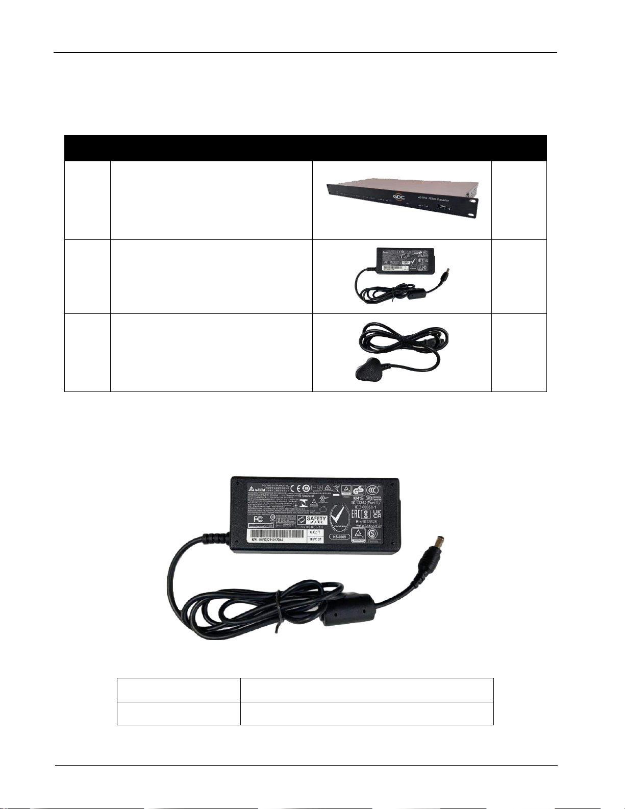
4PACKING LIST........................................................................................................6
4.1 Power Adapter Specifications .......................................................................... 6
5AE-6703 FRONT AND REAR PANEL DESCRIPTION............................................7
5.1 Front Panel ......................................................................................................... 7
5.2 Back Panel.......................................................................................................... 8
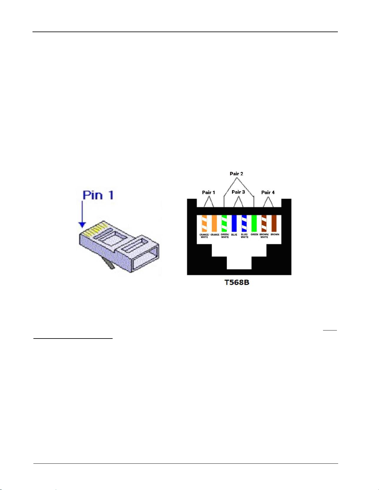
6ETHERNET/ AES3 WIRE CONNECTION................................................................9
7SAFETY INSTRUCTIONS .....................................................................................10
8REGULATORY INFORMATION ............................................................................12
9ROUTING DIAGRAM AND TYPICAL APPLICATION ...........................................13
10 INSTALLATION AND CONFIGURATION .............................................................14
10.1 Device List........................................................................................................ 14
10.2 Network Connection........................................................................................ 15
10.3 Software required for AE-6703 Configuration .............................................. 16
10.4 Configuring the IP Address for AE-6703 ....................................................... 16
11 CONFIGURING THE AES67 SEND STREAM.......................................................19
11.1 Create AES67 Output Stream (AE-6703) ....................................................... 19
11.2 Delete AES67 Output Stream (AE-6703)........................................................ 21
11.3 Create AES67 Output Stream (Q-SYS Core) ................................................. 21
12 CONFIGURING THE AES67 RECEIVE STREAM .................................................22
12.1 AE-6703 receives AES67 Multicast Stream................................................... 22
12.2 Q-SYS Core receives Multicast Stream created by AE-6703 ...................... 23
13 APPENDIX.............................................................................................................25
13.1 AE-6703 Firmware Version Upgrade Procedure........................................... 25
13.2 AE-6703 Input/Output LED Indicator Switch................................................. 29
13.3 AE-6703 Dante®Mode ..................................................................................... 30

- 3 -
February 16th, 2023
GDC AE-6703 AES67 CONVERTER USER MANUAL
1. FUNCTIONAL OVERVIEW
1 FUNCTIONAL OVERVIEW
The GDC AE-6703 is a bidirectional converter capable of converting 32 channels of audio in each direction
concurrently (total of 64 channel processing). It allows 32 channels of AES3 audio input to be transmitted as
AES67 network audio while at the same time allowing another 32 channels of AES67 network audio input to be
output as AES3 audio.
The AE-6703 AES67 Converter operates in the multicast mode based on the AES67 standard which is
compatible with Dante®, so it can communicate with related devices. The AE-6703 can be configured according
to the user’s requirements via the supplied software application. The external interface of the device is AES3,
which is used to connect AES3 input and output devices.

- 4 -
February 16th, 2023
GDC AE-6703 AES67 CONVERTER USER MANUAL
2. DIMENSIONS
2 DIMENSIONS
Figure 1: Dimensions of AE-6703 Unit

- 5 -
February 16th, 2023
GDC AE-6703 AES67 CONVERTER USER MANUAL
3. PRODUCT SPECIFICATIONS
3 PRODUCT SPECIFICATIONS
AES3 Input Voltage
2-7Vp-p
AES3 Impedance
110 Ohm balanced
Number of Audio Channels
32 x 32
AES67 Sample Rate
48K
Maximum Input/Output
0 dBFS
AES3 Input Sample Rate
44.1K, 48K, 88.2K, 96K
AES3 Output Sample Rate
48K
AES3 Output Voltage
3.3V p-p
AES3 Input Port
4 x RJ-45
AES3 Output Port
4 x RJ-45
AES67 In/Out Port
2 x RJ-45
Mains Plug
C14
Main Input Voltage
DC 12V, 1.0A, Max. 50 - 60Hz
Maximum Power Consumption
12W
Dimensions (WxHxD)
483 x 44 x 195 mm (1U)
Shipping Dimensions (WxHxD)
545 x 140 x 275 mm
Net Weight
3.2 KG
Shipping Weight
3.5 KG
Table 1

- 6 -
February 16th, 2023
GDC AE-6703 AES67 CONVERTER USER MANUAL
4. PACKING LIST
4 PACKING LIST
The AE-6703 AES67 Converter package consists of the components listed under Table 2.
Sr. No.
Part Description
Photo
Quantity
①
AE-6703 AES67 Converter unit
1 PCS.
②
Power Adapter#
1 PCS.
③
Power Cable
1 PCS.
# Refer to Section 4.1 for power adapter specifications
Table 2
4.1 Power Adapter Specifications
Figure 2: AE-6703 Power Adapter
Adapter Input
AC 100V –240V, 1.0A, Max. 50 –60Hz
Adapter Output
DC 12V, 5.417A, Max 65W
Table 3

- 7 -
February 16th, 2023
GDC AE-6703 AES67 CONVERTER USER MANUAL
5. AE-6703 FRONT AND REAR PANEL DESCRIPTION
5 AE-6703 FRONT AND REAR PANEL DESCRIPTION
5.1 Front Panel
Figure 3: AE-6703 Front Panel Indicators
①→ 32-Channel Audio Signal Indicator
From left to right are the 1 to 32 channel audio signal indications, indicating whether the channel
has audio signal input or output. By default, the factory setting is output indication. For more details
on modifying the audio signal indicators, please refer to Section 13.2.
②→Operating Status Indicator (Power)
After the device self-test is normal, the light keeps flashing, indicating that the device is running
normally.
③→Audio Data Reception Indicator (AES67)
After the receive route is configured, this indicator lights up, indicating that the received audio data
from AES67 is normal.
④→ Error Indicator (!)
When the device is operating normally, this indicator is not lit. It is lit whenever an error occurs.
⑤→Input Status Indicator (IN)
This indicator is lit when the audio signal light is configured for AES3 input indication.
⑥→Output Status Indicator (OUT)
This indicator is lit when the audio signal light is configured for AES3 output indication.
⑦→Debug Serial Port
It is only used for engineering debugging and not used during normal operation.

- 8 -
February 16th, 2023
GDC AE-6703 AES67 CONVERTER USER MANUAL
5. AE-6703 FRONT AND REAR PANEL DESCRIPTION
5.2 Back Panel
Figure 4: AE-6703 Back Panel Connectors
①→DC 12V Power Interface (positive inside and negative outside)
For safety, use only the supplied power adapter.
②→Network Interface AES67(A)and AES67(B)
When connecting a switch, users can only use one of the interfaces and cannot connect two interfaces to
the same switch.
③→Four sets of AES3 Input Interfaces (Input)
The interface is in the form of RJ-45 and each interface corresponds to eight input channels. There is an
indicator light on each side of the interface. The left light indicates whether the first four channels have
input signals and the right light indicates whether the last four channels have input signals. As long as any
one of them has a signal, the corresponding indicator light will light up.
④→Four sets of AES3 Output Interfaces (Output)
The form and indicator light distribution of the output interface are the same as those of the input
interface. When the indicator at the corresponding position is lit, it means that the corresponding four
channels have output signals.

- 9 -
February 16th, 2023
GDC AE-6703 AES67 CONVERTER USER MANUAL
6. ETHERNET/ AES3 WIRE CONNECTION
6 ETHERNET/ AES3 WIRE CONNECTION
▪Network Connection: AES6703 uses a standard gigabit network interface. Please use a Gigabit Switch and
a network cable to connect the equipment, please refer to T568B for the interface standard.
▪AES3 Digital Connection: When AE-6703 is connected to AES3 input/output device, use a good quality
shielded Category 6 network cable. The interface standard is T568B and the corresponding relationship
between the four pairs and the channel is as follows:
▪Pair 1 corresponds to channel 1-2
▪Pair 2 corresponds to channel 3-4
▪Pair 3 corresponds to channel 5-6
▪Pair 4 corresponds to channel 7-8
NOTE: For details regarding the AES3 connections on the SR-1000 Extreme -24 IMB; please refer to the ‘GDC
SR-1000 Installation Manual’.

- 10 -
February 16th, 2023
GDC AE-6703 AES67 CONVERTER USER MANUAL
7. SAFETY INSTRUCTIONS
7 SAFETY INSTRUCTIONS
Explanation of Graphical Symbols:
The triangle with the lightning bolt is used to alert the user to the risk of electric shock.
The triangle with the exclamation point is used to alert the user to important operating or
maintenance instructions.
The CE-mark indicates compliance with low voltage and electromagnetic compatibility.
Symbol for earth/ground connection.
Symbol indicating that the equipment is for indoor use only.
Symbol for conformity with Directive 2002/96/EC and Directive 2003/108/EC of the European
Parliament on waste electrical and electronic equipment (WEEE).
WARNING: TO REDUCE THE RISK OF ELECTRIC SHOCK, DO NOT ATTEMPT TO OPEN
ANY PART OF THE UNIT. NO USER-SERVICEABLE PARTS INSIDE. REFER SERVICING
TO QUALIFIED SERVICE PERSONNEL.
TO COMPLETELY DISCONNECT THIS APPARATUS FROM THE AC MAINS,
DISCONNECT THE POWER SUPPLY CORD PLUG FROM THE AC RECEPTACLE.
THE MAINS PLUG OF THE POWER SUPPLY CORD MUST REMAIN READILY
ACCESSIBLE.
DO NOT EXPOSE THIS EQUIPMENT TO RAIN OR MOISTURE, DRIPPING OR
SPLASHING LIQUIDS. OBJECTS FILLED WITH LIQUIDS, SUCH AS VASES, SHOULD
NOT BE PLACED ON THIS APPARATUS.
WHEN THE UNIT IS INSTALLED IN RACK CABINET OR A SHEFL, MAKE SURE THAT IT
HAS SUFFICIENT SPACE ON ALL SIDES TO ALLOW FOR PROPER VENTILATION (50
CM FROM THE FRONT AND REAR VENTILATION OPENINGS).
CONNECTIONS TO THE MAINS SHALL BE DONE ONLY BY AN ELECTROTECHNICALLY
SKILLED PERSON ACCORDING TO THE NATIONAL REQUIREMENTS OF THE
COUNTRIES WHERE THE UNIT IS SOLD.

- 11 -
February 16th, 2023
GDC AE-6703 AES67 CONVERTER USER MANUAL
7. SAFETY INSTRUCTIONS
IMPORTANT SAFETY INSTRUCTIONS
1. Read these instructions carefully.
2. Do not use this equipment near water.
3. Clean only with a dry cloth.
4. Do not block any ventilation openings. Install in accordance with the manufacturer’s instructions.
5. Do not use near heat sources such as stoves, heat registers, radiators or other
equipment (including amplifiers) that produces heat.
6. Do not use the unit near open fire sources.
7. Connect the unit only to the electric network with grounding. Use only electric plugs
that provide grounding.
8. Protect the power cord from being walked on, pinched or otherwise damaged.
9. Use only accessories specified by the manufacturer.
10. Unplug this unit during lightning storms or when unused for long periods.
11. Refer all servicing to qualified service personnel. Servicing is required when the system has
been damaged in any way, such as power supply cord or plug is damaged, liquid has been
spilled or objects have fallen into the unit, the unit has been exposed to rain or moisture, does
not operate normally or has been dropped.
12. WARNING - TO REDUCE THE RISK OF FIRE OR ELECTRIC SHOCK, DO NOT EXPOSE THIS
SYSTEM UNIT TO RAIN OR MOISTURE.
THIS UNIT CONTAINS POTENTIALLY LETHAL VOLTAGES. TO PREVENT ELECTRIC
SHOCK OR HAZARD, DO NOT REMOVE THE COVER. NO USER-SERVICEABLE PARTS
INSIDE. REFER SERVICING TO QUALIFIED SERVICE PERSONNEL.
INSTALLING OF THIS UNIT MUST BE PERFORMED ONLY BY QUALIFIED TRAINED PERSONNEL
FOLLOWING APPLICABLE SAFETY RULES. DO NOT ALLOW INSTALLING OF THIS UNIT IF
INSTALLATION HARDWARE IS BROKEN, BENT, PARTS ARE MISSING OR IS OTHERWISE
DAMAGED.

- 12 -
February 16th, 2023
GDC AE-6703 AES67 CONVERTER USER MANUAL
8. REGULATORY INFORMATION
8 REGULATORY INFORMATION
FCC COMPLIANCE STATEMENT
This device complies with Part 15 of the FCC rules. Operation is subject to the following two conditions:
(1) This device may not cause harmful interference and (2) this device must accept any interference received,
including interference that may cause undesired operation.
CAUTION: Changes or modifications not expressly approved by the party responsible for compliance could
void the user’s authority to operate the equipment.
NOTE: This equipment has been tested and found to comply with the limits for a Class B digital device, pursuant
to Part 15 of the FCC Rules. These limits are designed to provide reasonable protection against harmful
interference in a residential installation. This equipment generates, uses and can radiate radio frequency energy
and, if not installed and used in accordance with the instruction manual, may cause harmful interference to radio
communications. However, there is no guarantee that interference will not occur in a particular installation. If this
equipment does cause harmful interference to radio or television reception, which can be determined by turning
the equipment off and on, the user is encouraged to try to correct the interference by one or more of the following
measures:
▪Reorient or relocate the receiving antenna.
▪Increase the separation between the equipment and receiver.
▪Connect the equipment into an outlet on a circuit different from that to which the receiver is connected.
▪Consult the dealer or an experienced radio/TV technician for help.

- 13 -
February 16th, 2023
GDC AE-6703 AES67 CONVERTER USER MANUAL
9. ROUTING DIAGRAM AND TYPICAL APPLICATION
9 ROUTING DIAGRAM AND TYPICAL APPLICATION
The below example consists of an SR-1000 Extreme -24 IMB, AE-6703, Q-SYS Core, DAC-2824 and network
or analog amplifiers. In this example; the 24 channels of AES3 audio from the SR-1000 Extreme -24 are
transmitted to the Q-SYS Core for audio processing via the AE-6703. The processed audio from the Q-SYS
Core is then transmitted back via the AE-6703 to a Digital-to-Analog Converter (DAC-2824) and then to analog
Amplifiers OR directly from the Q-SYS Core to the network amplifiers that accept AES67 inputs.
Figure 5 illustrates the routing diagram for the AE-6703. The AES3 output device (SR-1000 Extreme -24) is
connected to the AES3 input interface of the AE-6703 and it can transmit its own audio signal to other AES67
devices on the network through the network.
The DAC or other AES3 receiving device is connected to the AES3 output interface of the AE-6703, which can
receive digital audio signals transmitted by the network.
Figure 5: Routing Diagram for AE-6703
Figure 6 depicts the typical connection method for the AE-6703 with the SR-1000 Extreme -24 IMB.
Figure 6: AE-6703 Typical Application

- 14 -
February 16th, 2023
GDC AE-6703 AES67 CONVERTER USER MANUAL
10. INSTALLATION AND CONFIGURATION
10 INSTALLATION AND CONFIGURATION
10.1 Device List
Sr. No.
Device Name
Photo
Quantity
①
GDC SR-1000 Extreme -24
1 PCS.
②
GDC AE-6703
1 PCS.
③
Q-SYS Core
1 PCS.
④
Gigabit Network Switch
1 PCS.
⑤
GDC DAC-2824
1 PCS.
⑥
RJ-45 AES Audio Cable
6 PCS.
⑦
Network Cable
3 PCS.
Table 4

- 15 -
February 16th, 2023
GDC AE-6703 AES67 CONVERTER USER MANUAL
10. INSTALLATION AND CONFIGURATION
10.2 Network Connection
Figure 7: Network Connection Diagram for AE-6703

- 16 -
February 16th, 2023
GDC AE-6703 AES67 CONVERTER USER MANUAL
10. INSTALLATION AND CONFIGURATION
10.3 Software required for AE-6703 Configuration
The AE-6703 device can be configured using the AudioGridController software. The provided
AudioGridController file needs to be renamed as “AudioGridController.exe” (please contact GDC for the
AudioGridController software file). Once renamed, double-click on this file in order to open the
AudioGridController interface on your laptop/PC.
NOTE: The AudioGridController.exe file can be opened on a laptop or PC running Microsoft Windows 7/
Windows 10/ Windows 11 Operating System.
Figure 8: AudioGridController Software
10.4 Configuring the IP Address for AE-6703
WARNING: Since this step requires the device to be rebooted; please complete this step before powering-up
the DAC or Amplifier in order to avoid hearing the reboot shock from the speakers.
In order to modify the IP Address of the AE-6703 device, make sure the network interface IPs of your
laptop/PC are set as follows:
▪Change the ‘IP Address’ to “169.254. xx. xx”.
▪Change the ‘Subnet mask’to “255.255.0.0”.
Run the AudioGridController software. When the software is run for the first time, the network settings window will
automatically be shown (as shown in Figure 9). Select the network interface card which is connected to the audio
network. You also can re-select the network interface card using the Options →choose netcard interface option.
Once done, restart the AudioGridController software.

- 17 -
February 16th, 2023
GDC AE-6703 AES67 CONVERTER USER MANUAL
10. INSTALLATION AND CONFIGURATION
Figure 9: Select Network Interface
As shown in Figure 10, click on the Device Config sub-tab. Select the device ‘GDC-a203-662d’from the
Select device drop-down list.
Figure 10: Modify IP Address
NOTE: In case you are unable to select any device in this drop-down list; click on the Device info sub-tab
and check if any ‘Unknown Device’is listed (refer to Figure 11). Confirm that the IP Address of your
laptop/PC and the IP Address of this ‘Unknown Device’belong to the same subnet (For example; as shown
in Figure 11, it should be 169.254.xx.xx).
If you can’t see any ‘Unknown Device’either, please make sure you select the correct network interface
card and check the connection with AE-6703.)

- 18 -
February 16th, 2023
GDC AE-6703 AES67 CONVERTER USER MANUAL
10. INSTALLATION AND CONFIGURATION
Figure 11: Check Device info sub-tab
Under the Network Config section, select the ‘Manually configure an IP address’ option and update the IP
Address and Subnet Mask values as per the cinema network. Click the Apply button and then click the
Reboot button. The AE-6703 device will automatically restart to complete the IP modification process.
Once the IP Address of the AE-6703 device has been modified, ensure that the network interfaces for the
Q-SYS Core, AE-6703 and SR-1000 Extreme -24 IMB are configured such that they belong to the same subnet
(in this example, 192.168.0.xx) as your laptop/PC.
Figure 12: Configure Network Interfaces for other devices

- 19 -
February 16th, 2023
GDC AE-6703 AES67 CONVERTER USER MANUAL
11. CONFIGURING THE AES67 SEND STREAM
11 CONFIGURING THE AES67 SEND STREAM
AES67 is a standard protocol. When a multicast stream is created by a device that is compatible with this
protocol, it periodically sends an SAP/SDP bulletin informing it of the information about the created multicast
stream, such as the multicast address, port, protocol type, sampling frequency, code bits, included channels,
and packaging time.
The parameters used by AE-6703 have 48KHz sampling rate, 24-bit encoding, 1ms packetization time and a
single multicast stream contains up to 8 channels.
The ‘AudioGridController’software is required to operate the AE-6703 device. This section provides a brief
description of the main content of the operation.
11.1 Create AES67 Output Stream (AE-6703)
As shown in Figure 13, open the AudioGridController software and select the device that needs to create a
multicast stream in the Select device drop-down box under the Device Config tab. Then, click the
Create/Delete button within the Multicast flow section to open the multicast flow operation interface.
Figure 13: Create AES67 Output Stream on AE-6703
Table of contents