GDD Instrumentation TxIII User manual

IP Transmitter
Model TxIII
1800W-2400V-10A
Instruction Manual
1963 rue Frank-Carrel, suite 203
Québec (Qc) Canada G1N 2E6
Tel.: (418) 478-5469
E-Mail: [email protected]
Web site: www.gddinstruments.com

Instrumentation GDD 2023-07-17 Page 3
TABLE OF CONTENTS
1. INTRODUCTION....................................................................................................................................... 17
2. SAFETY .................................................................................................................................................... 17
3. TRANSMITTER DESCRIPTION .......................................................................................................... 17
3.1 EQUIPMENT LIST................................................................................................................................................17
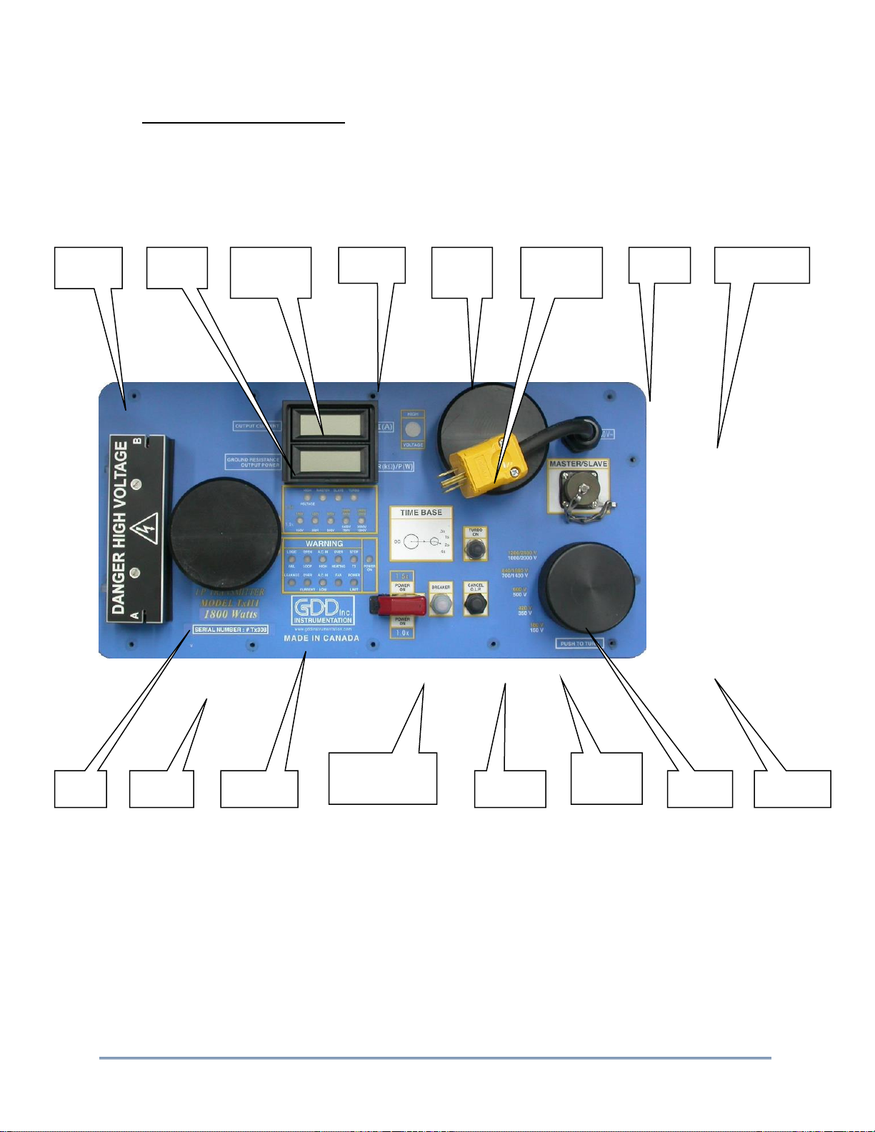
3.2 TRANSMITTER COMPONENTS................................................................................................................................17
3.2.1. Output Terminals................................................................................................................................. 17
3.2.2. Status LEDs.......................................................................................................................................... 17
3.2.3. Ohmmeter and Wattmeter Display ..................................................................................................... 17
3.2.4. Current Display.................................................................................................................................... 17
3.2.5. High Voltage Indicator......................................................................................................................... 17
3.2.6. Time Base / DC Selector (optional)...................................................................................................... 17
3.2.7. Power Cable......................................................................................................................................... 17
3.2.8. Master-Slave Interface ........................................................................................................................ 17
3.2.9. Vent Pipe ............................................................................................................................................. 17
3.2.10. Serial Number................................................................................................................................. 17
3.2.11. Warning LEDs.................................................................................................................................. 17
3.2.12. Power switch: ON (1.5x) / OFF / ON (1.0x) ..................................................................................... 17
3.2.13. Circuit Breaker ................................................................................................................................ 17
3.2.14. Cancel O.L.P. Switch (open loop protection) ................................................................................... 17
3.2.15. Turbo Switch ................................................................................................................................... 17
3.2.16. Voltage Selector.............................................................................................................................. 17
4. TRANSMITTER OPERATION ...................................................................................................................... 17
4.1 STEPS TO FOLLOW ..............................................................................................................................................17
4.2 OUTPUT POWER................................................................................................................................................ 17
5. MASTER / SLAVE MODE ........................................................................................................................... 17
6. TROUBLESHOOTING.......................................................................................................................... 17
7. TECHNICAL HELP...................................................................................................................................... 17
8. SPECIFICATIONS....................................................................................................................................... 17
9. GLOSSARY ................................................................................................................................................ 17

Instrumentation GDD 2023-07-17 Page 4
1. INTRODUCTION
The GDD TxIII transmitter is used for time-domain induced polarization survey. Its transmission
cycle is 2 seconds ON, 2 seconds OFF. Other timings are available upon request. It is sturdy and
can operate in extreme climatic conditions (40oC to 65oC).
The GDD Tx III transmitter can be powered directly from a 120 VAC power source (240 VAC
optional), such as a portable regulated generator. The TxIII transmits up to 10 A in a highly
conductive ground or sends up to 2400V in a resistive ground for a total power of 1800W.
Because of its power and light weight, the TxIII increases the average daily productivity of an IP
crew doing a dipole-dipole survey. For example, Géosig Inc., a Québec contractor, averages a
productivity of over 4 km a day for n=6, a=25 m, and a crew of 5 persons.
The GDD TxIII is easy to use and automatically stops within microseconds if a short circuit occurs
or if the circuit opens. There is also an emergency stop button that shuts down quickly all power
inside the transmitter. However and for user safety, we strongly recommend always wearing
electrically insulated shoes and gloves while operating the transmitter.
Safety Hints:
Wear electrically insulated shoes. They should be approved by certified
organization (CSA, ANSI) i.e. marked with the logo:
Wear electrically insulated gloves rated class 1 (7,5 kV).
2. SAFETY

Instrumentation GDD 2023-07-17 Page 5
3. TRANSMITTER DESCRIPTION
3.1 Equipment list
When receiving a GDD 1800W-2400V-10A IP Transmitter, model TXIII, ensure that it contains the
following elements:
One (1) TxIII transmitter built in a transportation box from Pelican
One (1) instruction manual
One (1) GDD Safe operating procedures (SOP)
One (1) GDD blue carrying case.
Optional
2, 25 or 50 meter electrical extension cord
GDD Master-Slave yellow cable
Do not hesitate to communicate with Instrumentation GDD if needed.

Instrumentation GDD 2023-07-17 Page 6
3.2 Transmitter components
Figure 1: Control panel
1-
Output
Termin
als
2-
Status
LEDs
3-
Ohmmete
r /
Wattmete
r
Display
4-
Current
Display
5-
High
Voltag
e
Indica
tor
6- Time
Base / DC
Selector
Optional
7-
Power
Cable
8-
Master/Slav
e interface
9-
Vent
Pipe
10-
Serial
Numb
er
11-
Warning
LEDs
12- Power
switch: ON
(1.5x) / OFF /
ON (1.0x)
13-
Circuit
Breaker
14-
Cancel
Open
Loop
Switch
15-
Turbo
Switch
16-
Voltage
Selector
Switch

Instrumentation GDD 2023-07-17 Page 7
3.2.1. Output Terminals
This is where the electrodes are connected. Press the button over each terminal to insert wires.
Be careful, the terminals can reach up to 2400 V.
3.2.2. Status LEDs
The red lights indicate the following elements:
HIGH VOLTAGE: This LED turns ON and OFF to indicate the presence of high voltage on the output
terminals, allowing the operator to follow the TxIII transmission cycle.
MASTER: This LED lights up for two reasons: when the transmitter is in stand-alone or in MASTER
configuration.
SLAVE: This LED lights up when the transmitter is in SLAVE configuration.
TURBO: This LED turns on when the turbo mode is activated, that is to say when the output
voltage changes from 700 V/840 V to 1400 V/1680 V or from 1000 V/1200 V to 2000 V/2400 V.
The lighted 150, 350, 500, 700/1400 or 1000/2000 red LEDs indicate the rated voltage present at
the output while transmitting. These values increase 120 % when the selector is on the 1.5X
mode.
3.2.3. Ohmmeter and Wattmeter Display
GROUND RESISTANCE: It displays the ground resistance when the generator is plugged and the
transmitter is powered OFF. The value shown is the contact resistance in kilo-ohms (x1000 Ω).
OUTPUT POWER: When the transmitter is transmitting (power switch in mode 1.0x or 1.5x), the
output power expressed in Watt is indicated instead of the contact resistance.
3.2.4. Current Display
Displays the output current (in A) and refreshes this value four times per second. The first and
the last reading may overlap the off cycle and have to be rejected.
3.2.5. High Voltage Indicator
3.2.6. Time Base / DC Selector (optional)
There is one possible time base selector. This optional time base selector allows the following
modes: 1s, 2s, 4s, 8s. The DC option is also available, allowing the transmitter to work as a DC
voltage source. To do so, place the DC switch to the left and the transmitter will work in DC mode.
To select a different time base, place the DC switch to the right and select the desired time base by

Instrumentation GDD 2023-07-17 Page 8
turning the rotary.
3.2.7. Power Cable
The termination of the power cable can be plugged into any 120 VAC /60 Hz voltage source. The
rated input voltage can be modified upon request to 220-240 VAC / 50-60 Hz. Please check
transmitter’s nameplate for specificity.
3.2.8. Master-Slave Interface
The Maser-Slave interface allows to link two transmitters with a synchronization cable to
increase the total output power and the output voltage of the system.
3.2.9. Vent Pipe
There are two vent pipes on the control panel. The FAN warning light indicates if the fan is
running. Make sure that the airflow is not being obstructed by any object (e.g.: leaves, snow, etc.).
3.2.10. Serial Number
Each instrument has its own serial number to identify it.
3.2.11. Warning LEDs
The red lights indicate the following problems:
LOGIC FAIL: Caused by an internal electronic failure.
LEAKAGE: A synchronization trouble caused a leakage current.
OPEN LOOP: This alarm is triggered when there is infinite resistance between the two output
terminals (the circuit is open) or when the output current is less than 30 mA (highly resistive
ground).
OVER CURRENT: This alarm is triggered when the current limit is exceeded. The current limit is
set to 10 A in normal mode and 5 A in DC mode.
A.C. IN HIGH: High (≥ 290 VAC) or irregular voltage from the generator. An unregulated generator
can trigger this alarm. The power transformer may overheat.
A.C. IN LOW: Low (≤ 170 VAC) or irregular voltage from the generator. An unregulated generator
can trigger this alarm.
OVERHEATING: The internal temperature of the transmitter is too high (≥ 85°C). Leave the
transmitter in this state until the LED turns off to let it cool off.
FAN: The FAN indicator lights up when the fan is running. The fan starts automatically to cool

Instrumentation GDD 2023-07-17 Page 9
down the transmitter when the temperature inside the transmitter is higher than 65°C.
STOP TX: Indicates that the transmitter stopped transmitting. This LED lights up with the warning
LEDs.
POWER LIMIT: Indicates that the power limit has been exceeded. This limit is set to 1800W.
POWER ON: Indicates that the transmitter is powered on.
3.2.12. Power switch: ON (1.5x) / OFF / ON (1.0x)
There are two Power modes: 1.0x and 1.5x. When the 1.5x mode is selected, the output voltage
will be 120 % higher and the power 150% higher compared to the 1.0x mode.
3.2.13. Circuit Breaker
There is a built in circuit breaker to protect the instrument from overload.
3.2.14. Cancel O.L.P. Switch (open loop protection)
The GDD TxIII has an internal open loop protection circuit to prevent direct electric shock to the
operator. This protection is triggered when the electrodes are not connected to the output
terminals or when the current is less than 30 mA.
NOTE: If the ground has a very high resistivity, the open loop protection could disrupt the
transmission of signal. To temporarily cancel the O.L.P. turn the TxIII OFF, press and hold the
Cancel O.L.P. button and turn the TxIII ON.
3.2.15. Turbo Switch
All voltage scales above 1200 V can be set with the Turbo switch. This switch allows to reach the
1400 V/1680 V or 2000 V/2400 V scales while the voltage selector is on the 700 V/840 V or
1000 V/1200 V position.
NOTE: It may take up to 4 seconds before the Turbo turns ON or OFF.
3.2.16. Voltage Selector
To set the output voltage, press and turn this selector to the right position. Pressing down this
knob will stop the current transmission. The available output voltages are:
1.0x mode: 150 V, 350 V, 500 V, 700 V, 1000 V, 1400 V and 2000 V.
1.5x mode: 180 V, 420 V, 600 V, 840 V, 1200 V, 1680 V and 2400 V.

Instrumentation GDD 2023-07-17 Page 10
4. TRANSMITTER OPERATION
4.1 Steps to follow
Here are the basic steps for a stand-alone operation of the TxIII:
1. Make sure that the TxIII is turned OFF.
2. Drive the electrodes into the ground and connect them to the output terminals with
insulated wires.
3. Start the generator.
4. Put the voltage selector to the lowest voltage scale (150 V) and turn the transmitter
ON (1.0x).
5. Increase the output voltage to increase the output power. It is not necessary to turn off
the transmitter to change the voltage scale or select a different time base (optional).
The 1.5x ON mode allows reaching an intermediate output power. Note that the
transmitter will automatically stop if you try to transmit more than 1800W. In this case,
select a lower voltage scale and turn the transmitter OFF and ON again to reset the
STOP TX alarm.
IMPORTANT:
Turn the transmitter OFF only when the “HIGH VOLTAGE” LED is off, which occurs in the OFF
time of the cycle or when the STOP TX light is triggered.
Turn the transmitter OFF before shutting down the generator.
4.2 Output Power
If a generator more powerful than 1800W is used, the output power will be limited to 1800W
by the TxIII. If the generator used cannot deliver up to 1800W, such as a 700W generator, the
output power will be limited by the generator.

Instrumentation GDD 2023-07-17 Page 11
5. MASTER / SLAVE MODE
Here are the basic steps for a Master/Salve operation of the TxIII:
1. Connect the yellow synchronization cable (Master/Slave) to the transmitters. The
Master/Slave cable terminations are different: one is labeled MASTER and the other one
SLAVE. The transmitter is MASTER or SLAVE according to the termination of the cable
connected on his interface. The MASTER and SLAVE LEDs indicate the mode of each
transmitter. (see figure 2, yellow line)
2. Connect an insulated wire between the terminal (A) of one transmitter and the terminal
(B) of the other one. (see figure 2, pink lines)
3. Connect the two power cables from the transmitters to the generator. (see figure 2, black
lines)
4. Drive the electrodes into the ground and connect them to the unused terminals (A) and (B)
by using insulated wires. (see figure 2, pink lines).
Figure 2 –Master/Slave system diagram

Instrumentation GDD 2023-07-17 Page 12
5. Make sure that the voltage selector is at the minimum scale (150V) on both transmitters.
6. Put the 1.0X / 1.5X switch to the 1.0x mode.
7. Gradually increase the output voltages from one transmitter to the other until the
transmitters stop.
Note: The selected voltage scale on both transmitters should not be more than one step
different, in order to have power that is as close as possible transmitted by both transmitters.
8. Reduce the output voltage of one transmitter by one step with the voltage selector.
9. Turn the Master transmitter OFF and ON.
NOTES
If the Master/Slave cable is not connected, the transmitter will work in stand-alone mode.
Both transmitters can be master or slave.
It is possible to reach 4800V with two transmitters in a Master/Slave system.
The current displayed on both transmitters should be the same (± 0.1 A).
The selected voltage scale on both transmitters should not be more than one step different,
in order to have power transmitted by both transmitters closer as possible.

Instrumentation GDD 2023-07-17 Page 13
6. TROUBLESHOOTING
With a good understanding of the transmitting circuit and a little logic, most of the problems that
will happen with the Tx III can often be solved.
1- Nothing seems to work
The ON LED doesn’t light up and the display remains blank: check if the power source
(generator) is working properly. Check also the power cable and the extension cord. The
breaker might also be trigged.
2- The ON LED lights up but the Tx-III does not transmit
First, check if the voltage selector is not pressed down. Then check which warning LEDs also
light up:
LOGIC FAIL: Indicates that an internal electronic failure occurred. Turn OFF and ON the Tx III.
If it doesn’t work, move the Tx III away from the current electrodes.
LEAKAGE: Turn OFF and ON the Tx III. If it doesn’t work, move the Tx III away from the current
electrodes.
OPEN LOOP: Can be caused by a cut wire or by highly resistive ground. In such a case, you
can bypass the open loop protection with the Cancel O.L.P. switch.
OVER CURRENT: The output current is too high. Reduce the output voltage or pull out a bit
the electrodes from the ground.
A.C. IN (HIGH or LOW): Indicates that the power source (generator) is defective. The supply
voltage must be stable and between 90 VAC and 140 VAC. Try to transmit less power with the
Tx III or change for another kind of generator.
WARNING: Always use a regulated generator. An unregulated generator could damage the
instrument which could not be covered by the warranty.
OVERHEATING: Indicates that the internal temperature of the Tx III is too high. Don’t turn
OFF the Tx III but leave it in this state to let the fan running and cool off the instrument.
POWER LIMIT: Reduce the output voltage.
STOP TX: This LED lights up when one of the previous problems is detected.

Instrumentation GDD 2023-07-17 Page 14
7. TECHNICAL HELP
3- The TxIII works well but the output power is very low
First, check if it is possible to increase the voltage. Every time you increase the voltage scale by
one step, the output power is approximately doubled. It is therefore possible to send 1000 W at
a given scale (e.g.: 2000 mA at 500 V) but the Tx III will stop transmitting on the next higher
scale (e.g.: 2800 mA at 700 V) since it would try to transmit around 2000 W. In such a case, try
the 1.5x mode at the 500 V scale in order to have an intermediate output power, e.g. around
1400 W (2400 mA at 600 V). You can also raise or lower the electrodes in the ground in order to
alter the overall resistivity of the circuit. This could allow you to transmit 1800 W at 700 V.
4- Ground with very high resistivity
If the ground is highly resistive, it is possible that the output current is too low even at the
maximum voltage. In such a case, you have to improve the electrode contact with the ground.
Here are a few suggestions:
Move the electrodes to get a better contact;
Double (or more) the number of electrodes;
Water the electrodes (with salt water if available).
5- Noise, Bad signal (Receiver)
The noise is an undesired interference or a disturbance that affects the signal.
The source of noise may be a second IP or EM transmitter operating in the area; the
interference zone may be as large as 10 kilometers, depending on the power of the instrument
and the system used. If a recurrent signal is received while the transmitter is powered off, this is
certainly due to a second transmitter. The receiver could even synchronize with the signal if
compatible.
Telluric currents may also cause the noise: they occur naturally near the surface of the earth
and concentrate in conductive zones such as overburdens, shale or graphite formation, etc. To
continue the survey in spite of telluric currents, one should improve the electrode contacts and
increase the output current of the transmitter in order to increase the signal-to-noise ratio.
Finally, the noise may originate from a defective transmitter or receiver. First, check the
electrodes, decrease the contact resistance and make sure there is no loose contact. The signal
timings of the receiver and the transmitter must be the same. If necessary, take a reading at a
precedent station or repeat tests with another receiver or transmitter.

Instrumentation GDD 2023-07-17 Page 15
If you encounter a problem that can’t be fixed or that is not described in the troubleshooting
section, or for any particular information, don’t hesitate to contact Instrumentation GDD :
Phone:(418) 478-5469
e-mail:info@gddinstruments.com
Any GDD Tx III transmitter that breaks down while under warranty or service will be replaced
free of charge upon request for the duration of repairs, subject to instruments availability,
except for shipping charges. Although this service is subject to instrument availability, we have
been able to honour this commitment until now.

Instrumentation GDD 2023-07-17 Page 16
8. SPECIFICATIONS
Size: Packing case: 56 x 35.5 x 56 cm (22.00" x 14.00" x 22.00")
Transmitter only: 50 x 30.5 x 45.7 cm (19.70" x 12.00" x 18.00")
Weight: Packing case: 12 kg (26.5 pounds)
Transmitter only: 26.5 kg (58.5 pounds)
Operating temperature: -40 oC to 65 oC (-40 oF to 150 oF)
Time Base: 2 s ON, 2 s OFF
Optional: - 1s, 2s, 4s, 8s
- DC
Rated output current: 0.030 A to 10 A (normal operation)
0.0 A to 10 A (cancel open loop)
Maximum of 5 A in DC mode
Rated output voltage: 150 V to 2400 V
LCD Displays:
Output current, 0,001 A resolution
Output power
Ground resistance (when the transmitter is turned off)
Power source: 120 V / 60 Hz
240 V / 50 Hz (Optional)

Instrumentation GDD 2023-07-17 Page 17
9. GLOSSARY
Induced polarisation (IP) is a geophysical technique: an electric current is induced into the ground
and the voltage decay is monitored trough electrodes to measure
its conductivity and chargeability. The GDD Tx III is one of the
principal components for an I.P. survey system.
Short circuit: Very low resistance connection between two nodes resulting in a fault current.
Transmitting circuit: The whole system associated with the Tx III: wires, electrodes, ground and
transmitter.
Open circuit: Infinite resistance between two nodes. It is the electrical opposite of a short circuit.
Conductive ground: Ground with a low electrical resistivity. Such grounds are usually associated
with thick overburden and waters presence (e.g.: swamp).
Resistive ground: Ground with a high electrical resistivity. Such grounds are usually associated
with bare rock or sand, with little overburden.
Table of contents