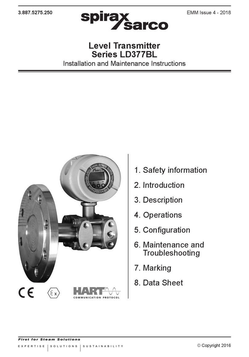
Spirax Sarco LD377B Series User manual

EXPERTISE SOLUTIONS SUSTAINABILITY
3.887.5275.230 EMM Issue 4 - 2018
© Copyright 2016
Dierential Pressure Transmitter
Series LD377B
Installation and Maintenance Instructions
1. Safety information
2. Introduction
3. Description
4. Operations
5.Conguration
6. Maintenance and
Troubleshooting
7.Marking
8. Data Sheet

23.887.5275.230

3
3.887.5275.230
1. Safety information
Safeoperationoftheseproductscanonlybeguaranteediftheyareproperlyinstalled,commissioned,
usedandmaintainedbyqualiedpersonnel(seeSection1.11 on this document) in compliance
withtheoperatinginstructions.Generalinstallationandsafetyinstructionsforpipeline andplant
construction,aswellastheproperuseoftoolsandsafetyequipmentmustalsobecompliedwith.
1.1 Intended use
The trasmitters object of the present instructions comply with the directive ATEX 2014/34/UE and
arecharacterizedbythefollowingmotodhdsofprotection:
II1/2GExdIICT6Ga/Gb
TheyaresuitableforinstallationinZone1,Zone2.
For connections and installation refer to this manual.
1.2 Access
Ensuresafeaccessandifnecessaryasafeworkingplatform(suitablyguarded)beforeattempting
toworkontheproduct.Arrangesuitableliftinggearifrequired.
1.3 Lighting
Ensureadequatelighting,particularlywheredetailedorintricateworkisrequired.
1.4 Hazardous liquids or gases in the pipeline
Consider what is in the pipeline or what may have been in the pipeline at some previous time.
Consider:ammablematerials,substanceshazardoustohealth,extremesoftemperature.
1.5 Hazardous environment around the product
Consider:explosion risk areas,lack of oxygen(e.g. tanks, pits),dangerous gases, extremesof
temperature,hotsurfaces,rehazard(e.g.duringwelding),excessivenoise,movingmachinery.
1.6 The system
Considertheeectonthecompletesystemoftheworkproposed.Willanyproposedaction(e.g.
closingisolationvalves,electricalisolation)putanyotherpartofthesystemoranypersonnelatrisk?
Dangersmightincludeisolationofventsorprotectivedevicesortherenderingineectiveofcontrols
oralarms.Ensureisolationvalvesareturnedonandoinagradualwaytoavoidsystemshocks.
1.7 Pressure systems
Ensure that any pressure is isolated and safely vented to atmospheric pressure. Consider double
isolation(doubleblockandbleed)andthelockingorlabellingofclosedvalves.Donotassumethat
thesystemhasdepressurisedevenwhenthepressuregaugeindicateszero.
1.8 Temperature
Allowtimefortemperaturetonormaliseafterisolationtoavoiddangerofburns.
1.9 Tools and consumables
Beforestartingworkensurethatyouhavesuitabletoolsand/orconsumablesavailable.Useonly
genuineSpiraxSarcoreplacementparts.

43.887.5275.230
1.10 Protective clothing
Considerwhetheryouand/orothersinthevicinityrequireanyprotectiveclothingtoprotectagainst
thehazardsof,forexample,chemicals,high/lowtemperature,radiation,noise,fallingobjects,and
dangerstoeyesandface.
1.11 Permits to work
All work must be carried out or be supervised by a suitably competent person. Installation and
operatingpersonnelshouldbetrainedinthecorrectuseoftheproductaccordingtotheInstallation
and Maintenance Instructions.
Whereaformal‘permittowork’systemisinforceitmustbecompliedwith.Wherethereisnosuch
system,itisrecommendedthataresponsiblepersonshouldknowwhatworkisgoingonand,where
necessary,arrangetohaveanassistantwhoseprimaryresponsibilityissafety.
Post‘warningnotices’ifnecessary.
1.12 Electrical work
Beforestartingworkstudythewiringdiagramandwiringinstructionsandnoteanyspecialrequirements.
Considerparticulary:mainssupplyvoltageandphase,local mains isolation, fuse requirements,
earthing,specialcables,cableentries/cableglands,electricalscreening.
1.13 Commissioning
Afterinstallationormaintenanceensurethatthesystemisfullyfuctioning.
Carry out test on many alarms or protective devices
1.14 Disposal
Unwanted equipment should be disposed of in a safe manner.
1.15 Returning products
CustomersandstockistsareremindedthatunderECHealth,SafetyandEnvironmentLaw,when
returningproductstoSpiraxSarcotheymustprovideinformationonanyhazardsandtheprecautions
tobetakenduetocontaminationresiduesormechanicaldamagewhichmaypresentahealth,safety
orenvironmentalrisk.ThisinformationmustbeprovidedinwritingincludingHealthandSafetydata
sheetsrelatingtoanysubstancesidentiedashazardousorpotentiallyhazardous.
Warning!
Exclusivelyfollowtheinstructionsindicatedinthisdocument.Failuretocomply
withthisdocumentmaycauseinjurytohealthormaydamagetheequipment.
SPIRAX SARCO®donottakesanykindofresponsibilityfordamagesduetofailure
to comply with this document.

5
3.887.5275.230
2. Introduction
2.1 Product Overview
TheSpiraxSarcoLDSerieselectronictransmittersaredevicesthatuseasensortomeasurepressure,
levelandtemperature,andtransmitacurrentsignal(4÷20mA)proportionaltothemeasuredvariable.
TheLDSeriesconsistsofthefollowingmodels:
TT372 Electronic temperature transmitter
LD276 Electronic pressure transmitter
LD377B Electronicdierentialpressuretransmitter
LD377BL Electronic level transmitter
2.2 Attention!
ThismanualdoesnotcontaininformationconcerningalltypeofTransmitteroralldierentinstallation
and/orworkingandmountingsolutions.
Formoreinformationorforparticularproblemsnotconsideredinthismanual,pleaseaddressto
ourtechnicaloce.
Thewarrantyperiodistheonecontemplatedinourgeneralservicingconditions.
This warranty is neither increased nor restricted by the contents of this manual.
ThisTransmitterhastobeinstalledandusedonlybyqualiedpersonswhohaverstcheckedthe
correctnessofsupplyvoltagesothatbothinstandardworkingconditionsandinpresenceofdamages
oftheplantorofanypartofit,nodangerousvoltagecanreachtheTransmitter.
AstheTransmittercanbeutilizedbothwithhighpressurevaluesandwithaggressivemediaitmust
beconsideredthatanincorrectuseofitcouldbringevenseriousdamagestopeopleandthings.
Acorrectandsafeworkingneedsanadequatetransport,stockandmountingotherthananappropriate
maintenance service.
SoitisnecessaryforthepeoplehandlingtheseTransmittertohaveknowledgeandexperiencein
mounting,servicingandworkingandtohavetitletodotheirjobwithreferenceto“SafetyStandards“.

63.887.5275.230
2.3 Denitions and Symbols
Inthismanualareusedthefollowingsymbolsandlabels:
Equipmentforuseinpotentiallyexplosiveatmospheres
II 1/2G
EquipmentGroupIICategory1/2G,suitableforpotentiallyexplosivearea(gases,
vapoursormists)tobeinstalledinaseparationwallbetweenZone0(process
side)andZone1(externalside)
Ex d DevicewithExplosionProofEnclosure
IIC GroupIICapparatus,tforsubstancesofgroupIIC,IIBandIIA(onlywhenused
intheambienttemperaturerange-40°Cto60°C)
IIB GroupIIB apparatus, t for substancesofgroupIIBandIIA(when used inthe
ambienttemperaturerange-40°Cto80°C)
TemperatureClassofthetransmitter(maximumsurfacetemperature)
T6, onlywhenusedintheambienttemperaturerange-40°C÷60°C
T5, onlywhenusedintheambienttemperaturerange-40°C÷80°C
Ga/Gb EquipmenttobeinstalledintheboundarywallbetweenanarearequiringEPLGa
and the less hazardous area
Warning!
Warning label, used to warn about hazardous materials, locations, or objects,
includingelectriccurrents,poisons,andotherthings.
Prohibition!
Prohibitionlabel,usedtoindicatesomethingisnotpermitted.
Mandatory!
Mandatorylabel,usedtosetobligationtaskstobeperformedbytheuser.
Information!
Informationlabel,usedtosetgeneralinformationfortheuserorwarnabouthazards
for the equipment.

7
3.887.5275.230
3. Description
TheLD357BseriesSMARTdierentialpressuretransmittersaremicroprocessorbasedinstruments
that combine the analog signal advantages (4-20mA) together with the exibility of digital
communicationusingHART®protocol.Theycanberemotelyconguredbyauniversalhandheld
terminal(HHT)orbyaPCwithadedicatedinterface.
Moreover,itispossibletolocallyconguretheinstruments(zeroandspan)bymeansofpush
buttonsandtodisplaythedataonthewideLCDdisplay.
ThetransmitterseriesLD357B,measuredierentialpressurewithspansfrom1.2to20000mbar
withastaticpressureupto200bar.Thepressuremeasuringelementisapiezoresitivesensor.It
is possible to choose a variety of sensors to satisfy all process conditions.
TheSpiraxSarcomeasuringcellcontainsthesensorandtransmitsthepressuretotheelectronics.
ThermaldriftiscompensatedusingthetemperaturesignalgeneratedbyaPTCthermistorintegrated
inthesensoritself.Basedonthesereadingsthemicroprocessorgeneratesthe4-20mAanalog
output"twowiressystem"anddisplaysthepressuremeasurementontheLCD.Someofthemain
characteristicsofthismicroprocessor-basedtransmitter,are:
- WideRangeability;
- Automatictemperaturecompensation;
- DigitalcommunicationusingHART®protocol.
Cable gland
Sensitive element
Enclosure
Fig. 1 - Dierential pressure transmitter LD357B
Process connection
Nom
Range
(mbar)
Span
min/max
(mbar)
Range Limits
min/max
(mbar)
0/18 1.2/18 -18/+18
0/50 3.3/50 -50/+50
0/350 23/350 -350/+350
0/1000 67/1000 -1000/+1000
0/2500 167/2500 -2500/+2500
0/5000 333/5000 -5000/+5000
0/10000 667/10000 -10000/+10000

83.887.5275.230
4. Installation
4.1 Transmitter Identication
Transmitterdatacanbefoundonthenameplatexedonthetopoftransmitterenclosure(seeMarking).
TheSerialNumbermustbequotedattheoccurrenceofaspecicrequesttothemanufacturer.
4.2 General mounting requirements
Priorinstallationshallbeobservedfollowingconsiderations:
- CheckwhetherTransmitter’soperatingconditionsarewithinthelimitsasreportedinthenameplate,
technicalspecicationssheetsand/orlabel.
- Make sure that the operating conditions are compatible with the specication given to the
manufacturer.
Mandatory!
- Formeasurementinthepresenceofparticularlyhotliquids(e.g.steam)make
surethattheTransmitterissuppliedwithasuitablennedarm.
- Forviscousliquidsorthosecontainingsolidparticlesinsuspensionmakesure
thattheconnectiontotheprocessisasuitableoneinordertoavoidclogs.
Warning!
Directsunlightmaycauseseriousdamagestotheinstrument.
Never install standard Transmitter under the sun or in any other location which
couldcausedirectoverheatingthroughradiation.
Fig. 2 - Mounting requirements
Zone 0
Direct
Sunlight
Zone 1

9
3.887.5275.230
4.3 Mechanical Installation
TheTransmittershouldbelocated,ifpossible,atsomeeasilyaccessible,welllightedplaceonthe
vessel,inordertoallowputtinginoperationsandmaintenancework.Locationshouldalsobesuch
thatambienttemperatureattheTransmitterenclosurebenotexcessive(seeMARKING).
Information!
- Plantoverpressure/over-temperature:observeratingplate.
- Installationonseismicareas:informtechnicaldepartment.
- Incaseofunstableuids:informtechnicaldepartment.
- Incaseofdamages:informtechnicaldepartment.
- Inspection frequency: consideration should be given to applicable national
legislation.
Warning!
- Theprocessconnectionmustberealizedin suchawaythatguaranteesthe
holdatthemaximumworkingpressureandtemperature.
- Do not overcome the maximum pressure and temperatures indicated in the
technical data sheet of the selected model.
- Whenthedeviceisconnectedtotheprocessitcanbesubmittedtohighpressures
and temperatures. To avoid accidents subsequent to sudden discharge of
pressureand/ortocontactwithdangerousorammableuidsitisnecessary
totakethemaximumattentionwhentheTransmitteristakeno,heatedor
repaired,verifyingthatitisisolatedfromtheprocessandisnotsubmittedto
pressure and/or temperature.

10 3.887.5275.230
4.4 Installation for relative pressure measurement
ThetransmittersLD357Bmaybeusedforrelativepressuremeasurementsorlevelmeasurements
intanksorpiping.InFig. 3thesimplestmounting,directonpiping,isillustrated.
Warning!
- Remembertointroducealwaysasecurityvalveinordertoputinmaintenance
operations when necessary.
- Whentheconnectionsarelocatedonaverticalprocessline,theowshouldbe
upward.
Information!
Fig. 3, Fig. 4, Fig. 5 e Fig. 6 show some of the installations recommended by ISO
2186Standards.RefertothisStandardformoreinformation.
+ side
- side (ATM)
Shut o valve
FLOW
Fig. 3 - Relative pressure measurements in piping lines

11
3.887.5275.230
- side
Fig. 4 - Level measurement in open vessels
Fig. 5 - Level measurements in closed vessels with corrosive vapors
Tank pressure
+ side
- side
+ side
Liquid lled

12 3.887.5275.230
Tank pressure
Information!
- ReferringtoFig. 5:thedescendingpipescanbelledwithcondensatevapors
oftheprocessuidorwithsuitableinertliquidtopreventdirectcontactwiththe
transmitterdiaphragm.
- ReferringtoFig. 6:thetransmittercanbemountedabovetheprocessconnections
onlywheninservicewithdryandcleangasvaporswithoutsealliquid.
Mandatory!
- PressureconnectionsonmodelLD377Baremarkedwith"H"("+")and"L"("-");
thehigherpressurewillbeappliedto"+"side.
- Alwayscheckcarefullyallmanifolds,reducersifany,ventsanddrainplugsfor
leaks.
Fig. 6 - Level measurements in closed vessels with dry and clean vapors

13
3.887.5275.230
4.5 Installation for dierential pressure measurement
5 ways manifold
LD377B
FLOW
Oriceange
Flowhorice
Fig. 7 - Dierential pressure measurements in piping
Mandatory!
- Alwayscheckcarefullyallmanifolds,reducersifany,ventsanddrainplugsfor
leaks.

14 3.887.5275.230
4.6 Electronic head orientation
Inordertorotatetheelectronicheadinthedesiredpositionyoumustfollowthesepassages(Fig. 8):
• unscrewthenut(A)withkeyCH.24;
• byhandgentlyrotatetheenclosure(B)inthedesiredposition;
• oncethedesiredpositionisreachedxthenut(A)againwiththesamekey.
Fig. 8 - Rotating the transmitter head
Information!
Itisnotnecessarytoturnothesupply.

15
3.887.5275.230
Loop4-20mA
For remote indicator
(OPTIONAL)
4.7 Electrical connection
Undertherearcapisplacedtheterminalblockreportingtheelectricpolarity(Fig. 9).
Insert the power supply cable into the enclosure through one of the two threaded openings.
Transmitter is protected from accidental inversion of polarity. For a better use is recommended
atwistedpair cable (22AWGmin).Avoidplacing Transmitternear devicespoweredinACor
Switching.Connectground-tapoftheTransmittertothelocalcommonearth(PE)asindicatedin
paragraphEarthing.
Warning!
Thethreadedopeningthatisnotusedmustbesealedusingasuitablecap.
Thecapsincludedinthedeliveryareonlyforprotectionduringtransport.
Fig. 9 - Electrical connection of the power cable to the terminal block
Information!
Impedance of the cables denes the possible maximum length for digital
communication.It'srecommendedusingcablewithalowimpedance.Themaximum
lengthofthepointtopointconnection,withaloadof250ohmandsingletwisted
cable22AWG-207pF/mit'sabout1000meters.
Themaximumconnectionlengthfortheanalogsignalonlyislimitedbytheloads
(connecteddevicesandcable)presentinthecurrentloop.
Toobtainoutputsignalof4-20mA,youhavetodeterminetheminimumsupplyvoltageasafunction
oftheloadrelation:seeFig. 10.Fromthefollowingformulayoucanachievetherightminimum
valueofsupplyvoltage:
Vdc = 0.0215xRL + 12
Where:RL= output load [Ohm].
The power supply source to assure a minimum current value of 24 mA.
Earthing
Loop
4-20mA

16 3.887.5275.230
Mandatory!
Inordertoobtaina4÷20mA+Hart®output a minimum load of 250 Ohm is required.
TAG -1 2 3 4
Vdc 12.5 17.4 24 25.2 30
Ohm 23 250 558 615 837
Fig. 10 - Operating area for Ex d protection
TheelectronictransmitterstotallycomplywiththeHART®protocolspecicationRevision6.0,sothey
includeremoteprocessvariableinterrogation,parametersettinganddiagnostics.
Thedeviceisa4÷20mA2-wiretransmitter,withFSKcommunication.
ItispossibletoreadviaHART®thefollowingvariables:
PV:transmittermainmeasure;
SV:%ofthespan;
TV:analogoutput;
QV: electronic board temperature.
Please refer to Fig. 11 for the Hart®modemconnectionontransmitter's4÷20mAloop.
In Fig. 12 the multidrop connection type is shown.
Operating area
Vdc

17
3.887.5275.230
Information!
Atmaximum15transmitterscouldbeconnectedinparallelonthesameline.
Attention: when more transmitters are connected on the same line the current
standingontheresistor(250-ohm)isequalto
4mA x N of connected instruments.
Thiscouldcauseahighelectricpotential.Besurepowersupplyissucient.
Fig. 11 - 4÷20 mA + Hart® modem connection
Fig. 12 - Only Hart® multidrop connection

18 3.887.5275.230
Fig. 13 - DCS connection
Mandatory!
Transmitter response time is <256ms.
DCS POLLING time must be set approximately at 800 ms in order to avoid
updatingproblemsbothinanaloganddigitalmeasurement.
OnrequestthetransmittercanbesuppliedinordertosupportaPollingtimeof
500 ms but with a minimal consumption of 5 mA.
4.8 Explosion Proof Protection
In case of use in areas with danger of explosion, it must be veried that the identied type of
transmittertsfortheclassicationofthezoneandforthepresenceofammablesubstancesin
theplant(seeMarking).
Thesafetyessentialrequisiteagainsttheriskofexplosionintheclassiedareasarexedfromthe
EuropeanDirectives2014/34/EUof26February2014(asfarasitconcernsthe'Equipment')and
1999/92/ECofDecember16th1999(asfarasitconcernsthe'WorkingEnvironment').
Warning!
Fortheelectricalconnectionspleasefollowtheinstructionsbroughtinthisoperator
manualstakingcarethatfortheuseinclassiedareasitisnecessarytoforesee
thestandardEN60079-14.
The accessories for cable entry (which must be threaded ½" NPT) must be
certied following the Standards EN 60079-Series (for Tamb >70°C must be
certiedforT>90°C).
Prohibition!
Donotopenthecoversoranypartofthedeviceindangerousareawhencircuitalive.
Forexplosionproofsafetyinstallation,itismandatorytodisconnecttheelectric
supplybeforeopeningthedevice.

19
3.887.5275.230
4.9 Earthing
Warning!
Theearthconnectionisrequiredtopreventdamagetopeopleandmalfunction
of the instrument.
- Case 1: Installing the instrument in a plant devoid of earthing systems
Inthecasewheretheplantdevoidofearthing,itisnecessarytoconnecttheearthwiretothe
terminalblockthroughthecablethatcarriesthesignalandthepowersupply(Fig. 9).
- Case 2: Installing the instrument in a plant provided with earthing systems
Makesuretheearthing(GND)ofthesystemhastheleastresistancepossible.
Fig. 14 - 4 ÷ 20 mA loop connection with plant provided with earthing systems
Warning!
In the case represented in Fig. 15,withintheearthwiremayalsoscrollthrough
thecurrentprotectionofotherinstrumentswheretheearthingofthesystem(GND)
had not been carried out in an optimal manner.
You can add an additional earth wire with section not less than 4 mm2to ensure such connection.

20 3.887.5275.230
Fig. 15 - Earthing in the housing
Warning!
Thehosemustnotbeconsideredasaprotectionagainstelectricshockforthe
protectionof security,butas protection against electromagnetic interferenceof
theinstrument.Therefore,inthecaseoflongdistancecable(L>20m),bothends
of the braid must be connected to the chassis or to the connectors. In the case
ofcablesL<20meters,willbesucienttoconnectthebraidonlyfromtheside
"Power Supply".
Fig 16 - Earthing of the sock for cables longer than 20 meters
This manual suits for next models
3
Table of contents
Other Spirax Sarco Transmitter manuals