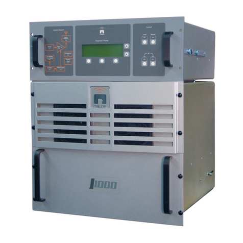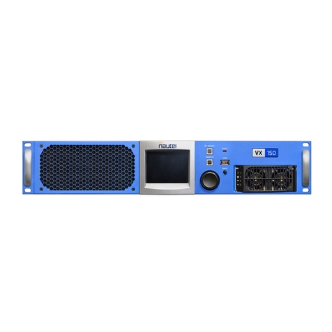
12 000 WATT AM BROADCAST TRANSMITTER
XL12
Contents (Page 1)
01 January 2002
TABLE OF CONTENTS
Section Page
1GENERAL INFORMATION
1.1 INTRODUCTION ...................................................................................................... 1-1
1.2 FACTORY SUPPORT............................................................................................... 1-1
1.3 PURPOSE AND SCOPE OF MANUAL ...................................................................... 1-1
1.3.1 FAMILY TREE .........................................................................................................1-1
1.4 PURPOSE OF EQUIPMENT ..................................................................................... 1-1
1.5 MECHANICAL DESCRIPTION .................................................................................. 1-1
1.6 TECHNICAL SUMMARY .......................................................................................... 1-1
1.7 SPECIAL TOOLS AND TEST EQUIPMENT ............................................................... 1-1
1.8 GLOSSARY OF TERMS .......................................................................................... 1-1
2INSTALLATION
2.1 PLANNING AND SITE PREPARATION...................................................................... 2-1
2.1.1 TRANSMITTER ROOM REQUIREMENTS...................................................................2-1
2.1.1.1 Transmitter Dimensions ......................................................................................2-1
2.1.1.2 Transmitter Clearances .......................................................................................2-1
2.1.1.3 Air Flushing .......................................................................................................2-1
2.1.1.4 Cooling..............................................................................................................2-1
2.1.1.5 Heating..............................................................................................................2-1
2.1.1.6 Work Area.........................................................................................................2-1
2.1.2 LIGHTNING PROTECTION ........................................................................................2-1
2.1.2.1 Station Reference Ground ...................................................................................2-2
2.1.2.2 AC Power Source...............................................................................................2-2
2.1.2.3 Antenna Feed Cable...........................................................................................2-2
2.1.2.4 Antenna/RF Output Disconnect ...........................................................................2-2
2.1.2.5 Antenna Tower...................................................................................................2-2
2.1.2.6 External Control/Monitor Wiring ...........................................................................2-2
2.1.3 ELECTRICAL POWER..............................................................................................2-2
2.1.3.1 Nominal Voltage.................................................................................................2-2
2.1.3.2 Voltage Stability.................................................................................................2-2
2.1.3.3 Power Consumption............................................................................................2-3
2.1.3.4 External AC Switching........................................................................................2-3
2.1.4 ANTENNA SYSTEM.................................................................................................2-3
2.1.4.1 RF Feed Cable...................................................................................................2-3
2.1.5 EXTERNAL RF DRIVE SOURCE ...............................................................................2-3
2.1.6 MODULATING AUDIO...............................................................................................2-3
2.1.6.1 Both Exciters Monaural (Internal or External RF Drive)...........................................2-3
2.1.6.2 Both Exciters AM Stereo (External RF Drive)........................................................2-4
2.1.6.3 One Exciter AM Stereo (External RF Drive)/One Exciter Monaural..........................2-4
2.1.6.4 Exciter 'A' AM Stereo (Optional C-QUAM AM Stereo Exciter as RF Drive Source.....2-4
2.1.7 SAFETY INTERLOCKS.............................................................................................2-4
2.1.7.1 External Electrical Interlock.................................................................................2-4
2.1.7.2 Internal Electrical Interlock ..................................................................................2-5
2.1.7.3 Mechanical Safety Interlock.................................................................................2-5
2.1.8 REMOTE CONTROL CIRCUITS .................................................................................2-5
2.1.8.1 On/Off Control....................................................................................................2-6
2.1.8.2 Main Exciter Selection........................................................................................2-6
2.1.8.3 Preset Power Level Selection ..............................................................................2-6
