GDS DuraRoll User manual

DuraRoll Roller Garage Door
Installation Instructions
For residential single and double size doors
ThermaRoll
Aluminium Roller Garage Door
DuraPass
Side-Hinged Personnel Door
DuraRoll
Steel Roller Garage Door
DuraTherm
Insulated Sectional Garage Door
!
!
HEAVY -
LIFT WITH
CAUTION!
!
!
YOUR SAFETY
FIRST!
Read this booklet
carefully before
installing your door
DuraRoll & DuraRoll Mini
2016 V1
www.samsondoors.co.uk
0800 328 6250
www.samsondoors.co.uk
0800 328 6250
www.samsondoors.co.uk

2
Both one and two-car doors are installed in
the same manner.
Be sure all warning labels and tags are
properly affixed to the door and that the home
owner information is left with the purchaser.
GENERAL NOTES
WHO SHOULD
INSTALL THIS DOOR?
A minimum of two people must be
available for fitting. However due to the
weight and spring tension of larger doors,
we insist that three people or suitable
lifting gear be available for installation on
doors over 10ft wide or 9ft high.
PRE-INSTALLATION CARE AND HANDLING
• The door curtain must be handled with care at
all times
• The doors length must be supported in its
entirety during transport and handling
• The door must be stored on a flat DRY surface
• Packaging must not be removed until
instructed (at the correct step in the
installation)
Ensure that the area around the opening is
strong enough to support the door.
!
!
!
!
WARNING!
FRAGILE!
WARNING!
KEYPOINTS: ELECTRICALLY
OPERATED DOORS
Please read the instructions relating to the
installation of an electric motor prior to
commencing. Key guidance is summarised
here and repeated at the relevant step in the
installation.
• The installed door must operate efficiently when
used manually. Ensure sufficient clearance
between door and bracket to facilitate fitting of
motor (See Side Clearance, page 4).
• Turn off the power before making any
adjustments.
• Make sure the anti-coning collar is adjusted
and secure on the drum shaft to eliminate
sideways movement on the opposite side to
which motor is to be fitted.
• When installing the door, ensure the motor is
disengaged and the drum turns freely.
• Never engage the manual release with motor
running.
• The upper limit on the operator should be set
to stop the roller door, 30-40mm below the
guide stop, to avoid damaging the drive gears.
• Weight bar must be attached to bottom bar
with rivets/bolts.
This new GDS door has been designed for ease of operation, security and attractive
appearance with minimal maintenance. Performance of the door will be impaired if it
is installed incorrectly. Read these instructions carefully before commencing the
installation. Warranty is void if the door is not installed correctly according to
these instructions.
!
!
Goggles
Safety Shoes
Gloves
SAFETY EQUIPMENT
www.samsondoors.co.uk
0800 328 6250
www.samsondoors.co.uk
0800 328 6250
www.samsondoors.co.uk

3
Tape measure
Stanley knife
Pencil
Spirit level
8,13 & 17mm sockets
8mm spanner
Masonry drill
Electric drill
‘A’ rated steps x2
Drill bit 10mm masonry
13mm steel bit
Square file
Two 18” pipe wrenches
Hammer
Screw drivers
Hacksaw
TOOLS REQUIRED FOR INSTALLATION
THE PACKED DOOR
!
!DO NOT REMOVE
ANY WRAPPING
UNTIL INSTRUCTED*
!
!CHECK FOR OBVIOUS
SIGNS OF DAMAGE AND
REFER TO WARNING LABEL
Curtain
Guides
Brackets
Fixings
*STEEL OUTER
WRAPPING CAN BE
REMOVED IF PRESENT
www.samsondoors.co.uk
0800 328 6250
www.samsondoors.co.uk
0800 328 6250
www.samsondoors.co.uk

4
BEFORE YOU START: OPENING SIZE
BEFORE YOU START: SIDE CLEARANCE
Opening
height
Opening width + overlap
Opening width
Garage opening
viewed from the inside
Door curtain roll
Curtain
overlap
Curtain
overlap
Door curtain size
Up to 2896mm (9’6”) wide &
2438mm (8’0”) high
Over 2896mm (9’6”) wide &
2438mm (8’0”) high
Guide size
30mmª
50mm
Overlap
each side
25mmª
50mm
OPENING WIDTH:
DuraRoll garage doors fit behind the garage opening.
Check that the door curtain supplied overlaps the opening
width at each side by the minimum requirements:
ªIn Ireland all door sizes are supplied with 50mm guides
OPENING HEIGHT:
The door will fit any opening height up to that
stated on the packaging, e.g. a 2134mm high door
can be fitted to a 2000mm high opening
Lintel
Opening
Width
Opening
Height
Side
Clearance
Side
Clearance
Headroom Backroom
Side clearance
Garage opening
viewed from the inside
Door curtain size
Up to 2896mm (9’6”) wide &
2438mm (8’0”) high
Up to 2896mm (9’6”) wide
Over 2896mm (9’6”) wide &
2438mm (8’0”) high
Over 2896mm (9’6”) wide
Guide
size
30mmª
30mmª
50mm
50mm
Side clearance
for manual doors
95mmª
each side
95mmª
each side
120mm
each side
120mm
each side
Side clearance for
doors with a motor
135mmª motor side
95mm non-motor side
165mmª motor side
95mm non-motor side
160mm motor side
120mm non-motor side
190mm motor side
120mm non-motor side
How much room do I need at the side of the garage opening?
The door is mounted onto brackets and the brackets must be set
in from the side of the garage opening by the minimum distance
to the outside edge of the bracket as shown in the table below.
Doors with a motor require extra clearance on the side the motor
is fitted - see table below.
To achieve the minimum side clearance you will need to cut the
ends of the door axle.
STANDARD DOORS
MINI DOORS
STRUCTURAL CONDITIONS OF OPENING:
The surface where the door is to be fitted must be flush and reasonably smooth. Small irregularities in
brick work will be acceptable. The lintel must not protrude backwards or forwards from the brick piers.
!
!
ªIn Ireland all door sizes are supplied with 50mm guides
www.samsondoors.co.uk
0800 328 6250
www.samsondoors.co.uk
0800 328 6250
www.samsondoors.co.uk

5
BEFORE YOU START: BACKROOM
BEFORE YOU START: HEADROOM
BEFORE YOU START: FITTING NOTES
BR
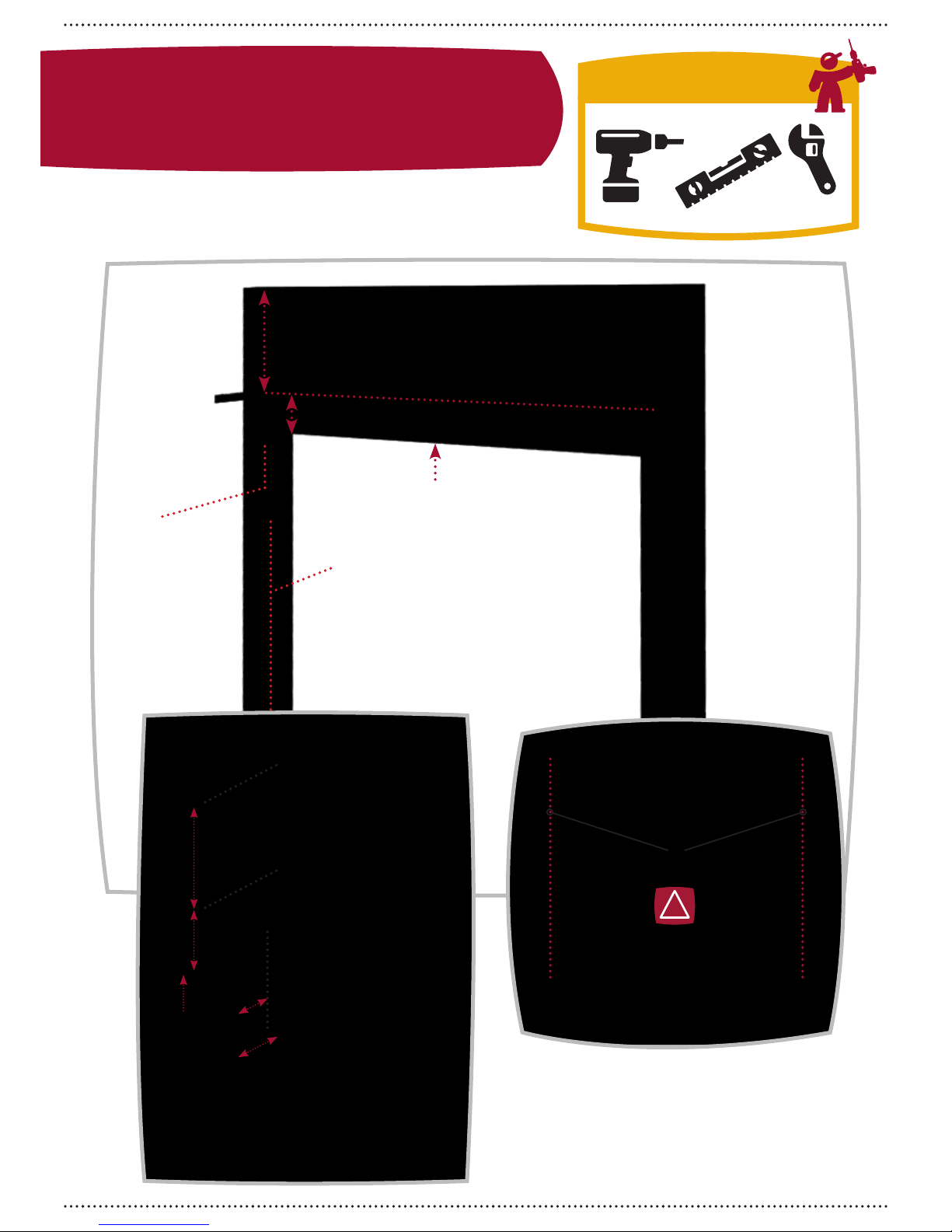
How much room do I need behind the garage opening?
The door curtain is mounted on brackets above the garage opening and projects back
into the garage. The door will require the minimum backroom as shown:
Door curtain size Door curtain size
All door sizes All door sizes
Guide size Guide size
30mm or
50mm
30mm or
50mm
Minimum backroom Minimum backroom
495mm 390mm
STANDARD DOORS MINI DOORS
How much room do I need above the garage opening?
The door curtain is mounted on brackets above the garage opening and to
allow maximum drive through height, the minimum headroom required is
shown in the table below.
If insufficient headroom is available to allow the door roll to be fitted fully
above the opening, the door may be fitted projecting down into the opening
up to a maximum of 100mm without the need for a fascia. If the door
projects down by more than 100mm a fascia (not supplied) will be required -
see figure 1.
Note: 10mm more headroom is required to install the door than is needed
to operate the door once installed. If the available headroom is right at the
minimum, the bracket can be fixed 10mm lower whilst the door roll is fitted
and tensioned and then tapped up by 10mm once the door is installed to
give full clearance with no hangdown.
*The minimum headroom but will require bracket position adjustment
during installation to achieve full opening height. (see page 9)
**The minimum headroom that requires no bracket position adjustment
during installation to achieve full opening height. (see page 9)
Garage opening
viewed from the inside
Door curtain size
Up to
2438mm (8’0”) high
Up to
2134mm (7’0”) high
Over 2438mm (8’0”) high &
up to 3048mm (10’0”) high
Minimum headroom
431mm* / 441mm**
343mm* / 353mm**
483mm / 493mm**
Up to 100mm hangdown
without the need for a fascia
Hangdown No Hangdown
100mm
FIGURE 1
STANDARD DOORS
MINI DOORS
Do not remove any wrapping, or steel protective outer
wrapping if fitted to your door, until instructed.
(a) Door package and its contents
should be checked for obvious damage before removal of
protective outer wrapping (If on your door).
(b) The door should only be fitted after any plastering of the area
has been completed. Plaster splashes will damage the pre-finish
on the curtain and cause premature wear of the nyloflex within
the guides.
(
c) The door must be fitted square and level irrespective
of the shape of the opening. On no account should any
compensation be made to suit an irregular opening
!
!EVEN IF THE
OPENING IS NOT
SQUARE OR LEVEL
THE DOOR MUST
ALWAYS BE FITTED
SQUARE & LEVEL
www.samsondoors.co.uk
0800 328 6250
www.samsondoors.co.uk
0800 328 6250
www.samsondoors.co.uk

6
UN
UN
UN
COMPONENTS
L
C 1x
E
F
H
1x
1x
1x
Left Guide
Curtain Stop, Nut & Bolt
Axle Saddle
Axle U-Bolt & 2x Flange Nuts
L
UN
G 1x
Lock Hole
Protective Cover
UN
D 4x
Guide Lug
L
1xB
Bracket
A
C
B
D
E
F
www.samsondoors.co.uk
0800 328 6250
www.samsondoors.co.uk
0800 328 6250
www.samsondoors.co.uk

7
UN
UN
UN
UN
R
R
C 1x
E
F
D
G
1x
1x
4x
1x
Universal (unhanded)
Right Guide
Guide Lug
Lock Hole
Protective Cover
Axle Saddle
Axle U-Bolt
& 2x Flange
Nuts
Handed - marked with
L (left) or R (Right)
Parts are handed (to fit on the left or right side
of the door) or unhanded (fitting to either left
or right side of the door). Any reference to
handing - left or right assumes you are viewing
the door from the inside. Items are not shown
to scale for clarity.
LR
UN
KEY
R
1xB
Bracket
1xA
Curtain
UN
H 1x
Curtain Stop, Nut & Bolt
FIXINGS LIST
2
1
M10 x 65mm
Sleeve anchor
Hex nut with
washer
M8 x 45mm
coach screws
22mm
washer
M10 x 50
Blue wall
plugs
OR
x14 x14
x14
x14
Your door will be supplied either with
sleeve anchors or coach screws and
plugs (both types are suitable for fitting
DuraRoll doors)
www.samsondoors.co.uk
0800 328 6250
www.samsondoors.co.uk
0800 328 6250
www.samsondoors.co.uk

8
Mark door position and
fix brackets
LINTEL
HEADROOM - DISTANCE ABOVE
BRACKET TO CEILING
BRACKET DISTANCE ABOVE LINTEL
DISTANCE THE CURTAIN
OVERLAPS THE OPENING
B
A
C
BRACKET
INSET
DISTANCE
FROM
OPENING
EDGE
D
LINTEL
B
A
D
C
!
!
C
Mark the door curtain overlaps on the
wall - ‘C’
Check that the door curtain supplied overlaps
the opening width at each side by the
minimum requirements:
C=25mm each side for 30mm guides
C=50mm each side for 50mm guides
TOOLS REQUIRED
www.samsondoors.co.uk
0800 328 6250
www.samsondoors.co.uk
0800 328 6250
www.samsondoors.co.uk

9
Mark the fixing position of the bracket
STANDARD DOOR
Distance from the bottom of the lintel to the top of the bracket:
A=200mm
Minimum headroom above the bracket
B=231mm* (doors up to 8’0”/2438mm high)
B=283mm* (doors over 8’0”/2438mm high)
For the full height of the opening to be available
A+B=431mm* (doors up to 8’0”/2438mm high)
A+B=483mm* (doors over 8’0”/2438mm high)
If the full headroom is not available (A+B=431mm/483mm),
the bracket can be fixed 241mm*/293mm* below the ceiling
with the door curtain projecting down into the opening by up to
a maximum of 100mm when fully open without the need for a
fascia - see page 5 for detail drawings.
The minimum distance from the edge of the opening to the
bracket is:
D= Curtain overlap (C) + 10mm min
D= Curtain overlap (C) + 185mm max
MINI DOOR
A=140mm from the bottom of the lintel to the top of the
bracket
B=203mm* minimum headroom above the bracket
A+B=343mm* for the full height of the opening to be available
with the door fully open
If the full headroom is not available (A+B=343mm), the bracket
can be fixed 213mm below the ceiling with the door curtain
projecting down into the opening by up to a maximum of
100mm when fully open without the need for a fascia.
The minimum distance from the edge of the opening to the
bracket is:
D=Curtain overlap (C) + 10mm min
D=Curtain overlap (C) + 185mm max
*Note: 10mm more headroom is required to install the
door than is needed to operate the door once installed.
If the available headroom is right at the minimum, the
bracket can be fixed 10mm lower whilst the door roll
is fitted and tensioned and then tapped up by 10mm
once the door is installed to give full clearance with no
hangdown. If this is the case, fix the brackets through
the slotted holes (step 1) to allow for tapping up once
the door roll is installed.
PARTS REQUIRED
2xB
E 2x
1xA
LR
UN
C 2x LR
UN
F 2x
FIXINGS REQUIRED
2 x6
OR
1
x6
1
2
!
!CHECK LEVELS
Fix the brackets in place at each
side of the opening.
www.samsondoors.co.uk
0800 328 6250
www.samsondoors.co.uk
0800 328 6250
www.samsondoors.co.uk

10
Prepare the guides
For automatic installations
the measurement from the
top of the horizontal leg of
the support bracket to the
bottom edge of the stop
bar is critical. It must never
be less than:
F=200mm Standard doors
F=140mm Mini doors
D=35mm Minimum on doors with 30mm guides
D=60mm Minimum on doors with 50mm guides
D=35mm Minimum on doors with 30mm guides
D=60mm Minimum on doors with 50mm guides
STANDARD DOOR FULL
HEADROOM AVAILABLE
MINI DOOR FULL
HEADROOM AVAILABLE
STANDARD DOOR RESTRICTED
HEADROOM AVAILABLE
MINI DOOR RESTRICTED
HEADROOM AVAILABLE
Cutting the guides to length:
Measure down from the top of the wall
bracket by:
F=200mm for Standard Doors
F=140mm for Mini Doors
Mark the wall. Measure from this point
to the finished floor level.
Transfer measurement (G) to the guide
measuring from the bottom of the stop
bar.
Shorten the guide to the required
length.
The distance shown from the top of the bracket to the
ceiling is the minimum required for the door to operate
once installed - 10mm additional space is required to
install the door - see the note at the foot of page 9.
*
FOR THE CORRECT OPERATION OF THE
DOOR, THE GUIDES MUST BE FITTED IN THE
POSITIONS ILLUSTRATED BELOW.
G
F
FLOOR LEVEL
E
200mm140mm
200mm140mm
D D
D D
F
E
E
100mm
Max
100mm
Max
231mm
Min**
203mm
Min
231mm
Min**
**283mm on
doors over
8’0/2438mm
high
**283mm on
doors over
8’0/2438mm
high
203mm
Min
STOP BAR
STANDARD
DOORS
F= 200mm
Mark the
wall here
MINI
DOORS
F= 140mm
!
!
!
!
* *
**
www.samsondoors.co.uk
0800 328 6250
www.samsondoors.co.uk
0800 328 6250
www.samsondoors.co.uk

11
Splay the guides creating a 3 sided funnel
effect, it is critical to (if not already done
so) to hammer flat the top 6” section that is
exposed by the top notch.
See step 1,
page 17
Position the fixing lugs: Hammer the second
from top (2) and bottom fixing (4) lugs into
place (figure 2) allowing a gap for the Lock
bar lug (see step 1 page 17).
(2)
(3)
(1)
(4)
Figure 2
1
1 2
2
PARTS REQUIRED
D 4x
www.samsondoors.co.uk
0800 328 6250
www.samsondoors.co.uk
0800 328 6250
www.samsondoors.co.uk

12
1
= =
Whilst the door is on the floor,
rotate the axle back and forwards
through the roll to centre it
Position the
door ready
for fitting with
the bottom
rail facing the
opening
The Axel will protrude 11” (280mm)
beyond the drum wheel at each side
Position and mount the door
3
2
2
3
Check axle length does not foul any
obstructions. Cut down if necessary
ensuring the axle is even and centred.
Lift the complete door curtain and axle
onto the brackets ensuring that the
roll is the correct way round with the
bottom rail as shown below.
Fit saddle and ‘U’ bolt, nut and
washers loosely at each support
bracket. See figure 1 for the location
of Standard (main slot) and figure 2
for Mini doors (small and main slot)
Bottom rail start
position
A minimum of two people must be
available for fitting. However due to the
weight and spring tension of larger doors,
we insist that three people be available for
installation on doors over 10ft wide
or 9ft high.
!
!
!
!
!
!
www.samsondoors.co.uk
0800 328 6250
www.samsondoors.co.uk
0800 328 6250
www.samsondoors.co.uk

13
5
5
4
4
MINI DOORS
STANDARD DOORS
Centre the door roll in the opening by
lifting the curtain and axle together
and moving either way using the
Curtain overlap marks on the wall as
a guide. Make sure the axle protrudes
evenly on both sides 11” (280mm)
from the drum wheel
Tighten the ‘U’ bolts with the bottom
rail at the start position as shown in
point 2.
IF AUTOMATION IS TO BE FITTED
SEE SEPARATE INSTRUCTIONS AT
THIS POINT (SUPPLIED WITH YOUR
AUTOMATION).
IF AUTOMATION IS REQUIRED –
TIGHTEN ONE END ONLY.
!
!
!
!
Figure 1 Figure 2
= =
www.samsondoors.co.uk
0800 328 6250
www.samsondoors.co.uk
0800 328 6250
www.samsondoors.co.uk

14
Up to 2 turns standard doors
Up to 3 turns mini doors
!
!
!
!
!
!
!
!
!
!
!
!
WARNING DANGER!
HIGH SPRING TENSION CAN CAUSE
SEVERE INJURY OR DEATH. REPAIRS
OR ADJUSTMENTS MUST BE MADE
BY 2 PEOPLE.
IMPORTANT NOTE: Pre-tension should
now be applied to the springs by
turning the curtain roll approx 2 turns
forward for standard door and 3 turns
for mini doors
The amount of pre-tension required
may vary with individual doors and
applications - See adjustments section
on page 16 and 17.
PRE-TENSION:- Do not cut the
CARDBOARD bands that hold the
door curtain in a roll. However, ,
if the door has a protective steel
wrapping, cut the bands and remove
this before you pre-tension.
Carefully cut the wrapping to expose a
small portion of the bottom rail. Hold
the door by the bottom rail before
removing all wrapping. DO NOT
RELEASE THE BOTTOM RAIL. The door
will have a strong tendency to rise,
WHICH IF UNCONTROLLED COULD
CAUSE SERIOUS DAMAGE OR INJURY
DUE TO SPRING TENSION. The door
must be held until both guides are
securely fixed in place.
NOTE: Knife marks or cutting of the
bottom seal or the nyloflex webbing
voids the door warranty
ENSURE THE DOOR CURTAIN IS
CENTRED. IF ADJUSTMENT IS REQUIRED,
CENTRE THE DOOR ROLL BY LIFTING
THE CURTAIN AND AXLE TOGETHER
A person must hold and control
the door curtain at all times
!
1
1
2
2
3
Overlap Mark
Curtain edge
CENTRE CURTAIN!
!
!
FIXINGS REQUIRED
2 x8
OR
1
x8
Tension the door & fix the guides
PARTS REQUIRED
G 2x
www.samsondoors.co.uk
0800 328 6250
www.samsondoors.co.uk
0800 328 6250
www.samsondoors.co.uk

15
4
Slide
Top Lug
Slide each guide onto the door
curtain allowing approx 3-5mm
clearance between edges of
curtain and inside edge of guide
to ensure door travels smoothly.
Drill wall and fix the top lug of
each guide with a 10mm x 65mm
sleeve anchor or coach screw.
4 5
5
CHECK GUIDES ARE VERTICAL
AND PARALLEL!
Fix the remaining lugs.
!
!
Fitting the stop bar catchers
THE BOTTOM EDGE OF THE GUIDE STOP
BARS MUST NOT BE CLOSER TO THE
HORIZONTAL PART OF THE SUPPORT
BRACKETS THAN DISTANCE ‘F’.
F=220MM STANDARD DOORS
F=140MM MINI DOORS
IF THIS IS NOT OBSERVED THE DOOR WILL
BE DIFFICULT TO CLOSE
IF THE BRACKETS
WERE FIXED 10MM
LOWER TO ALLOW
FOR FITTING ON THE
LIMIT OF HEADROOM
CLEARANCE, THESE CAN
NOW BE TAPPED UP
TO ACHIEVE THE FINAL
POSITION. BRACKET
LEVEL MUST BE CHECKED
ON COMPLETION OF
TAPPING UP.
!
!
!
!
1Stop bar
pre-drilled
hole
F
STOP BAR
To access the
pre-drilled hole
for the stop bar,
pull away the
bottom rubber
seal, fit and
reposition the seal
www.samsondoors.co.uk
0800 328 6250
www.samsondoors.co.uk
0800 328 6250
www.samsondoors.co.uk

16
IF THE DOOR IS NOT SET PROPERLY
COMPLETE THE FINAL ADJUSTMENT
SECTION (P18) BEFORE CUTTING
THE LOCK BAR HOLES.
!
!
Check door settings
GUIDES: Now that you have both guides
firmly fixed, pull the curtain down slowly.
Continue to pull the curtain down to the
floor ensuring that it runs freely. If it does
not, reposition guides for clearance 3-5mm
as necessary (fixing lugs are slotted for
adjustment - figure 3).
CONING: Check that the door rolls up
evenly and squarely with the ends of the roll,
if it rolls out unevenly (cones out at one end)
repeat FINAL adjustment section on page 16.
DOOR TENSION: The door is now
installed. Lower the door curtain to the half
open position to check that the spring tension
is in balance. From this position the door
curtain does not rise or lower of its own accord
when released.
The door should be slightly over tensioned
during this running in period. i.e. when put
to the ground it should want to rise 25mm -
40mm unless locked down.
Coning
Coning
effect on
curtain
Figure 3
PARTS REQUIRED
D
G
2x
2x
www.samsondoors.co.uk
0800 328 6250
www.samsondoors.co.uk
0800 328 6250
www.samsondoors.co.uk

17
TO MARK THE GUIDES FOR
THE LOCK BAR HOLES,
THE DOOR MUST BE FULLY
CLOSED WARNING: DO NOT RAISE DOOR
WITH THE KEY IN LOCK!
Position the final guide lug aligned
with the lock bar slots, fit the finger
protection lock bar covers and fix in
place.
!
!
!
!
Cut lock bar holes & fit finger protection
Engage the lock bar to mark the point of entry
within the guides. Mark position of lock bar on
the back of the guide.
Floor level
3
3
12
Note: To ensure maximum efficiency of the
weather seal it will be necessary to ensure
a very neat fit between the locking bar and
the slot in the guide. When the lock bars
are engaged the weather seal should be
compressed against the floor.
!
!
SECURITY NOTE FOR AUTOMATIC
DOORS
To stop attempts to prise the bottom of the door up,
the curtain can be secured to the drum wheel.
Fully close the
door, mark the
corrugation just
before the curtain
leaves the top
roll. Open the
door partially,
approximately
400mm, so you
are able to see
the mark.
Drill through the
curtain and drum
wheel rim and fix with
a self tapping screw.
18mm high x
13mm wide
MARK DRILL
Then drill a series of holes and file
out a guide slot, just large enough
to accept each lock bar.
www.samsondoors.co.uk
0800 328 6250
www.samsondoors.co.uk
0800 328 6250
www.samsondoors.co.uk

18
Final adjustments & troubleshooting
DIFFICULT TO OPERATE IN EITHER
DIRECTION
(a) Check that the curtain is not jamming in the
guides.
(b) Check running clearance in the guides (3-
5mm per side).
DIFFICULT TO CLOSE
Decrease the spring tension (See spring tension
adjustments page 19).
GUIDE/AXLE RELATIONSHIP (SEE FIGURE 3)
If the door is very difficult to close during the
last 600mm of travel, check that the guides are
fitted in the correct relationship to the brackets
and that the axle is the correct distance from
the wall. (see step 3, page 10, 11). One or
both will be incorrect, thereby increasing lead
angle into the mouth of the guides, making the
door difficult to close.
CONING (SEE FIGURE 4)
If the curtain rolls up unevenly (cones out at
one end) and the bottom rail appears out of
parallel with the door roll and guides, check
for the following:
(a) Brackets not level.
(b) The axle is not the same distance back from
the wall at each side.
(c) Axle not correctly centralised in roll.
If the brackets are level and the axle distance
from the wall is equal at both sides, remove
the coning by moving the axle through the roll
in the opposite direction to the coning.
This operation should be done by minimum of
two people and ensure the door is fully rolled
up to minimise spring tension before starting.
CONING ADJUSTMENTS
Follow the steps in final spring tension
adjustments, (see next section) up to (e) where
it states “to increase tension”. Do not rotate the
axle unless spring tension is to be changed.
While still retaining a firm hold on the axle to
prevent axle rotation using a pipe wrench, the
axle should be lightly tapped in the direction of
the coning (See figure 4). Move no more than
20mm at a time. Then follow the steps and
secure axle. After adjustment the door needs
to be opened and closed 2-3 times to settle
the new alignment. You may need to repeat
this step a number of times.
If coning persists, fitting of an anti coning
collar/exhaust clamp (1 3/8”/35mm) may be
necessary. Note the side to which the door is
coned and, with the door closed, fit an anti
coning collar onto the axle tight against the
boss of the drum wheel to prevent movement
to the left or right as the door opens or closes.
(Figure 5)
Figure 4:
Coning
Figure 5:
Coning Clamp
220-
250mm
Figure 3
!
!
LIGHT
TAPS!
www.samsondoors.co.uk
0800 328 6250
www.samsondoors.co.uk
0800 328 6250
www.samsondoors.co.uk

19
MAINTENANCE
The following suggestions will keep the
door working efficiently.
1. Do not grease or oil the guides.
2. Periodically clean the inside of the
guides with white methylated spirits or
similar and spray with silicone spray or
car/furniture polish.
3. It may be necessary to lubricate the
locking mechanism via the key hole
using graphite dust lubricant if operation
becomes difficult.
4. Your door should be washed with a
quality car shampoo at least every 2
months to prevent the build up of dirt,
salt and other corrosive substances. If
your door is installed within 2 miles of
the sea, your door should be cleaned in
this way at least monthly.
WARNING! DANGER! HIGH
SPRING TENSION CAN CAUSE
SEVERE INJURY OR DEATH. REPAIRS
OR ADJUSTMENTS MUST BE MADE
BY TWO PEOPLE USING PROPER
TOOLS AND INSTRUCTIONS.
!
!
FINAL SPRING TENSION ADJUSTMENTS
(SEE FIGURE 6)
AS A PRECAUTION, ATTACH A PIPE
WRENCH AT THE OPPOSITE END TO
BE WORKED ON AND ENSURE IT IS HELD
TIGHTLY BY ANOTHER PERSON.
(a) One ‘U’ bolt clamp should be selected to
loosen first and the other side should remain
fully tightened. The remaining tight ‘U’ bolt
clamp will retain the existing tension when
the door is fully open (rolled up). However,
as a precaution a pipe wrench must be also
be attached to the axle at the opposite side to
be worked on and held tightly by one of the
installers.
THIS OPERATION SHOULD NOT BE
ATTEMPTED WITH THE DOOR IN THE
CLOSED POSITION AS THE TENSION IS
VERY MUCH GREATER AND COULD LEAD
TO DAMAGE OR SERIOUS INJURY.
(b) Loosen but do not fully remove the selected
‘U’ bolt clamp.
(c) One person should then grip the axle on
that side firmly with an 18” pipe wrench.
(d) The other person should then move to the
other end of the door roll and with an 18”
pipe wrench, grip the axle firmly. Loosen but
do not fully remove the other ‘U’ bolt clamp
until the axle is free.
(e) To increase tension pull down on the pipe
wrench and to decrease tension allow the pipe
wrench to move up (see figure 6).
(f) Fully tighten adjacent ‘U’ bolt clamp while
holding tension with a pipe wrench. Do not
release pipe wrench until ‘U’ bolts are tight.
(Ensure that it never slips as this would cause
loss of tension and possible injury or damage
to door).
Decrease
tension
Loosen U-bolt
Increase
tension
Figure 6:
Tensioning
!
!
!
!
www.samsondoors.co.uk
0800 328 6250
www.samsondoors.co.uk
0800 328 6250
www.samsondoors.co.uk

20
Garage Door
Systems Limited,
Wakehurst Ind.
Est., Ballymena,
BT42 3AZ
Call:
Northern Ireland: 028 2565 5555
UK 0870 242 3 242
Republic of Ireland 1850 510 510
Email: info@gdsdoors.eu
Web: www.gdsdoors.eu
Garage Door Systems reserves the right to alter specifications to design and manufacture without notification.All specifications are correct at time of publication,errors and omissions excepted. February 2015 Issue 1
!
!
HEAVY -
LIFT WITH
CAUTION!
!
!
YOUR SAFETY
FIRST!
Read this booklet
carefully before
installing your door
www.samsondoors.co.uk
0800 328 6250
www.samsondoors.co.uk
0800 328 6250
www.samsondoors.co.uk
This manual suits for next models
1
Table of contents
Other GDS Garage Door Opener manuals
Popular Garage Door Opener manuals by other brands

King gates
King gates JET XL Series Installation and use instructions and warnings

Chamberlain
Chamberlain B970 owner's manual

Anaheim Automation
Anaheim Automation 3255ADM 1/2 HP owner's manual

FAAC
FAAC 740 D manual

Chamberlain
Chamberlain LiftMaster Security+ 3265CM-267 owner's manual

CAME
CAME C Series STANDARD INSTALLATION