8 9
Due to constant improvements to and further developments of our designs, the information and illustrations in this brochure are non-binding.
The specifications and mounted lengths provided by the machine manufacturer must be observed. All specifications are in mm.
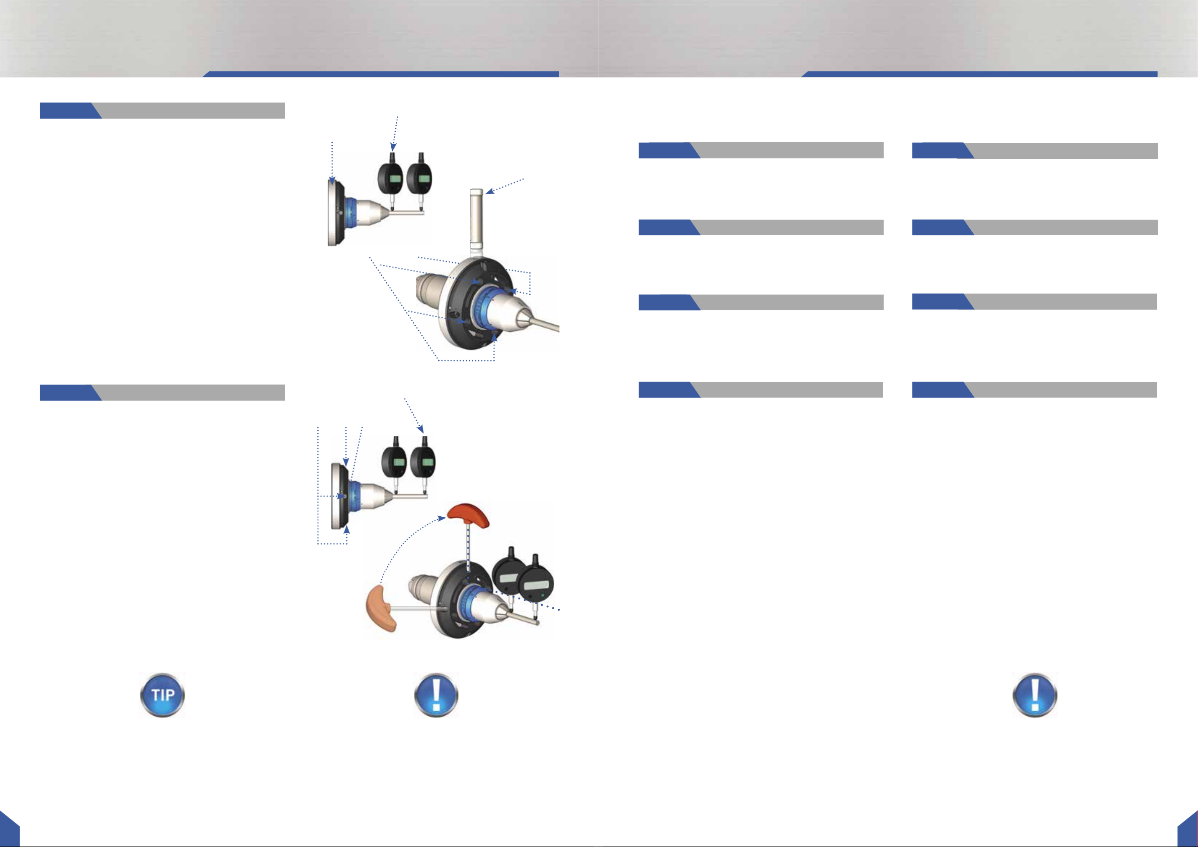
Adjustment Run-out and Repeatability
Focus on first dial gauge.
Run-out is adjusted by tapping on the adjustment area
with the adjustment hammer (3).
1. Constantly turn A-axis until the dial gauge reaches
the peak. Reduce this value by half in lightly tapping
the adjustment area with the adjustment hammer.
2. Repeat this procedure until you adjusted run-out to
0,001 mm. Now tighten the four mounting screws
crosswise with 12Nm.
3. Unclamp and clamp the test pin three to five times, so
the µGrind chuck can settle and tensions disappear.
4. Check the run-out again and readjust, if necessary.
Focus on second dial gauge.
1. Lightly tighten the 4 adjustment screws.
2. Constantly turn A-axis and stop, when the dial gauge
reaches the peak.
3. Tighten the adjustment screw closest to the peak point
using the wrench (4), so the dial gauge result is halved.
4. Turn the chuck for two to three rounds. If wobble is
still detectable repeat step 2 and 3 until run-out and
wobble are below 0,001mm.
5. Mount the swarf guard again.
6. Now you can start grinding.
Step 2:
Step 3:
Run-Out
Wobble
Depending on the application, regular run-out checks
are recommended.
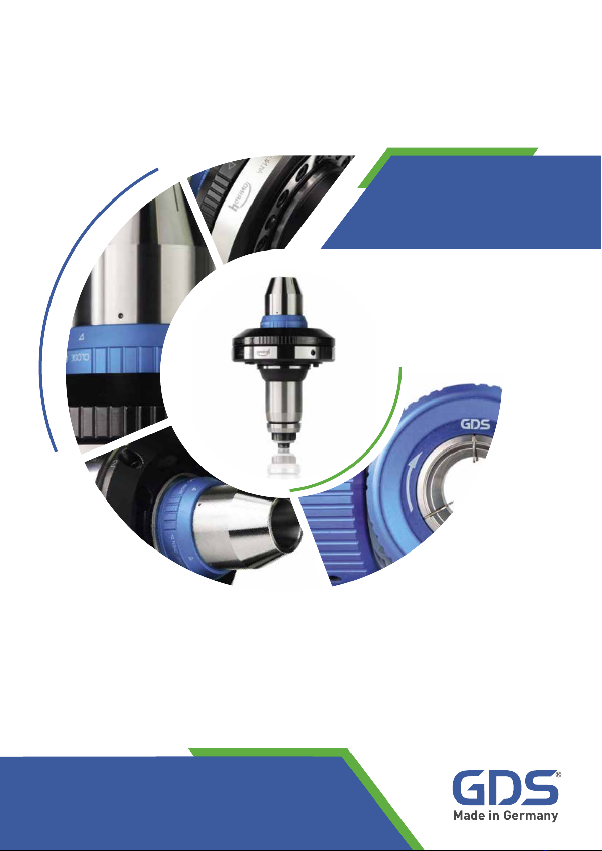
first dial gauge
second dial gauge
adjustment area
4 adjustment screws
4 mounting screws
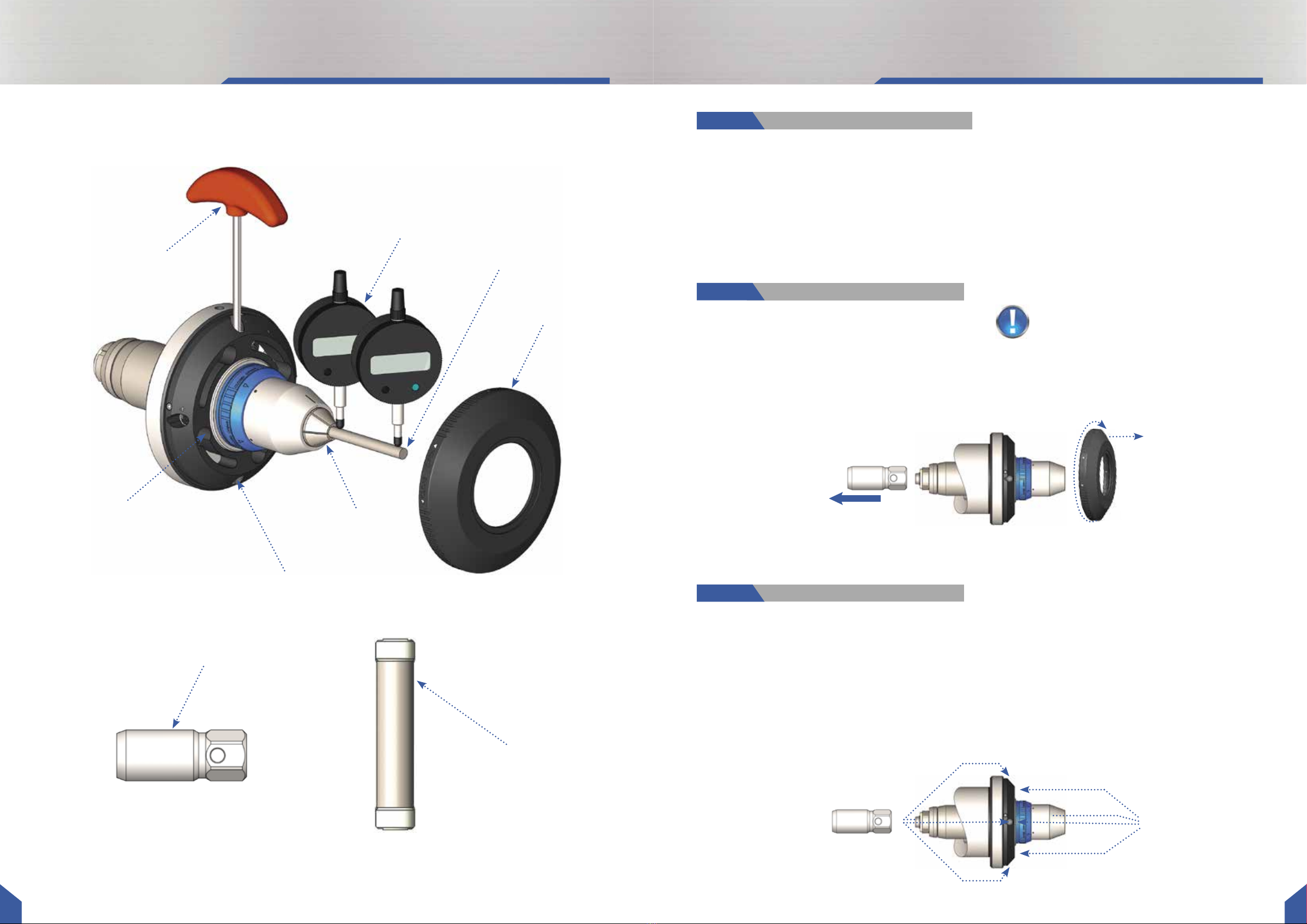
Change clamping sleeve // Remove chuck
Change clamping sleeve Remove chuck
adjustment hammer
Important:
make sure that the µGrind does not contact coolant
hoses etc. during your grinding process.
Always clean the µGrind chuck after use. Store chuck
in anticorrosive environment.
• Move push rod into forward position to unclamp
the chuck. Remove the test pin/ blank/ tool.
• Screw the new clamping sleeve into the chuck, fol-
lowing the descriptions on page 6.
• Turn the blue locking ring from CLOSE to OPEN and
unscrew the clamping sleeve.
• clamp a new test pin to check the run-out and
wobble using two dial gauges.
Step 1:
Step 3:
Step 2:
Step 4:
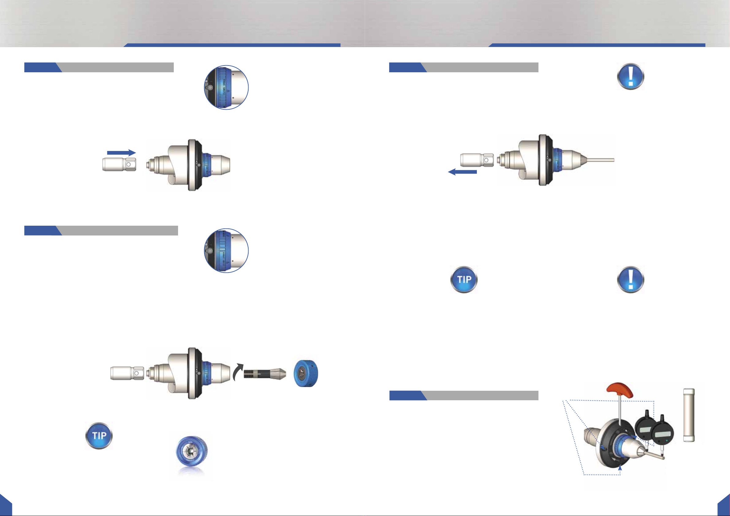
• Move push rod into forward position to open the
chuck. Remove the test pin/ blank/ tool.
• Remove the swarf guard and loosen the four adjust-
ment screws with the wrench (4).
• Turn the blue locking ring from CLOSE to OPEN and
unscrew the clamping sleeve.
• Move push rod backwards.
• Loosen the four mounting screws.
• Remove the µGrind chuck from the machine
spindle and store in the original bag.
Pay attention to store the chuck in an anticorrosive
environment.
• Remove push rod from the machine spindle.
• Keep the µGrind chuck and accessories in the
µGrind case.
Step 1:
Step 3:
Step 2:
Step 4:
Important:
if you wish to remove the µGrind chuck with an HPS
clamping sleeve mounted, a test pin/ blank/ tool
must remain clamped in the clamping sleeve to assure
chuck
and clamping sleeve not to be damaged.