4 5
As a result of continuous improvement and further development of our designs, the information and illustrations in this brochure are not binding.
The specifications and installation lengths of the machine manufacturer must be observed. All specifications are in mm. Errors and omissions excepted.
(ISO 2768 -f)
Winkelmaße
- 6
>6-30
>30-120
>120-400
>400-1000
>1000
0,05
0,1
0,15
0,2
0,3
0,5
- 10
>10-50
>50-120
>120-400
>400
1°
30`
20`
10`
5`
Längenmaße
12
20
46 46
100
1
F
8
7
6
5
4
3
2
1
8
7
6
5
4
3
2
A
B
C
D
E
F
A
B
C
D
E
Weitergabe sowie Vervielfältigung dieses Dokuments, Verwertung und Mitteilung seines Inhalts sind verboten, soweit nicht ausdrücklich gestattet.
Zuwiderhandlungen verpflichten zu Schadenersatz. Alle Rechte für den Fall der Patent-, Gebrauchsmuster- oder Geschmacksmustereintragung vorbehalten
Einstelldorn D20d12 komplett
Schutzvermerk
DIN 34 beachten
GDS
Präzisionszerspanungs GmbH
11
A3
1:1
Material <nicht festgelegt>
0.17
Gewicht (kg):
/
Status
Material:
Blatt / von
Benennung:
Artikelnummer:
Format
Maßstab
Rohabmessung:
DIN 6 T1 -
Proj.methode 1
AR
Name
10.05.2019
Datum
Gepr.
Erstellt
Name
Datum
Änderung
Rev
Allgemein-
toleranzen
DIN ISO 2768-mK
Zeichnungsnummer:
020.172.009Z
Oberflächenbehandlung:
250002825
100
46
ø 20
ø 12
46
1
F
8
7
6
5
4
3
2
1
8
7
6
5
4
3
2
A
B
C
D
E
F
A
B
C
D
E
Weitergabe sowie Vervielfältigung dieses Dokuments, Verwertung und Mitteilung seines Inhalts sind verboten, soweit nicht ausdrücklich gestattet.
Zuwiderhandlungen verpflichten zu Schadenersatz. Alle Rechte für den Fall der Patent-, Gebrauchsmuster- oder Geschmacksmustereintragung vorbehalten
Backenfutter SHARK
Schutzvermerk
DIN 34 beachten
GDS
Präzisionszerspanungs GmbH
Basisfutter
11
A3
1:1.5
Material <nicht festgelegt>
5.90
Gewicht (kg):
/
Status
Material:
Blatt / von
Benennung:
Artikelnummer:
Format
Maßstab
Rohabmessung:
in Arbeit
DIN 6 T1 -
Proj.methode 1
AR
Name
14.04.2021
Datum
Gepr.
Erstellt
NameDatum
Änderung
Rev
Allgemein-
toleranzen
DIN ISO 2768-mK
Zeichnungsnummer:
020.172.000Z001
Oberflächenbehandlung:
250002905
1
F
8
7
6
5
4
3
2
1
8
7
6
5
4
3
2
A
B
C
D
E
F
A
B
C
D
E
Weitergabe sowie Vervielfältigung dieses Dokuments, Verwertung und Mitteilung seines Inhalts sind verboten, soweit nicht ausdrücklich gestattet.
Zuwiderhandlungen verpflichten zu Schadenersatz. Alle Rechte für den Fall der Patent-, Gebrauchsmuster- oder Geschmacksmustereintragung vorbehalten
Backenfutter SHARK
Schutzvermerk
DIN 34 beachten
GDS
Präzisionszerspanungs GmbH
Basisfutter
11
A3
1:1.5
Material <nicht festgelegt>
5.90
Gewicht (kg):
/
Status
Material:
Blatt / von
Benennung:
Artikelnummer:
Format
Maßstab
Rohabmessung:
in Arbeit
DIN 6 T1 -
Proj.methode 1
AR
Name
14.04.2021
Datum
Gepr.
Erstellt
NameDatum
Änderung
Rev
Allgemein-
toleranzen
DIN ISO 2768-mK
Zeichnungsnummer:
020.172.000Z001
Oberflächenbehandlung:
250002905
Adjusting screw
(ISO 2768 -f)
Winkelmaße
- 6
>6-30
>30-120
>120-400
>400-1000
>1000
0,05
0,1
0,15
0,2
0,3
0,5
- 10
>10-50
>50-120
>120-400
>400
1°
30`
20`
10`
5`
Längenmaße
1
F
8
7
6
5
4
3
2
1
8
7
6
5
4
3
2
A
B
C
D
E
F
A
B
C
D
E
Weitergabe sowie Vervielfältigung dieses Dokuments, Verwertung und Mitteilung seines Inhalts sind verboten, soweit nicht ausdrücklich gestattet.
Zuwiderhandlungen verpflichten zu Schadenersatz. Alle Rechte für den Fall der Patent-, Gebrauchsmuster- oder Geschmacksmustereintragung vorbehalten
Schutzvermerk
DIN 34 beachten
GDS
Präzisionszerspanungs GmbH
11
A3
1:2
Material <nicht festgelegt>
16.16
Gewicht (kg):
/
Status
Material:
Blatt / von
Benennung:
Artikelnummer:
Format
Maßstab
Rohabmessung:
DIN 6 T1 -
Proj.methode 1
AR
Name
10.05.2019
Datum
Gepr.
Erstellt
NameDatum
Änderung
Rev
Allgemein-
toleranzen
DIN ISO 2768-mK
Zeichnungsnummer:
Oberflächenbehandlung:
1
F
8
7
6
5
4
3
2
1
8
7
6
5
4
3
2
A
B
C
D
E
F
A
B
C
D
E
Weitergabe sowie Vervielfältigung dieses Dokuments, Verwertung und Mitteilung seines Inhalts sind verboten, soweit nicht ausdrücklich gestattet.
Zuwiderhandlungen verpflichten zu Schadenersatz. Alle Rechte für den Fall der Patent-, Gebrauchsmuster- oder Geschmacksmustereintragung vorbehalten
Backenfutter SHARK
Schutzvermerk
DIN 34 beachten
GDS
Präzisionszerspanungs GmbH
Basisfutter
11
A3
1:1.5
Material <nicht festgelegt>
5.90
Gewicht (kg):
/
Status
Material:
Blatt / von
Benennung:
Artikelnummer:
Format
Maßstab
Rohabmessung:
in Arbeit
DIN 6 T1 -
Proj.methode 1
AR
Name
14.04.2021
Datum
Gepr.
Erstellt
NameDatum
Änderung
Rev
Allgemein-
toleranzen
DIN ISO 2768-mK
Zeichnungsnummer:
020.172.000Z001
Oberflächenbehandlung:
250002905
Spring
1
F
8
7
6
5
4
3
2
1
8
7
6
5
4
3
2
A
B
C
D
E
F
A
B
C
D
E
Weitergabe sowie Vervielfältigung dieses Dokuments, Verwertung und Mitteilung seines Inhalts sind verboten, soweit nicht ausdrücklich gestattet.
Zuwiderhandlungen verpflichten zu Schadenersatz. Alle Rechte für den Fall der Patent-, Gebrauchsmuster- oder Geschmacksmustereintragung vorbehalten
Backenfutter SHARK
Schutzvermerk
DIN 34 beachten
GDS
Präzisionszerspanungs GmbH
Basisfutter
11
A3
1:1.5
Material <nicht festgelegt>
5.90
Gewicht (kg):
/
Status
Material:
Blatt / von
Benennung:
Artikelnummer:
Format
Maßstab
Rohabmessung:
in Arbeit
DIN 6 T1 -
Proj.methode 1
AR
Name
14.04.2021
Datum
Gepr.
Erstellt
NameDatum
Änderung
Rev
Allgemein-
toleranzen
DIN ISO 2768-mK
Zeichnungsnummer:
020.172.000Z001
Oberflächenbehandlung:
250002905
Tension rod
Mounting screw
Machine
spindle
1
F
8
7
6
5
4
3
2
1
8
7
6
5
4
3
2
A
B
C
D
E
F
A
B
C
D
E
Weitergabe sowie Vervielfältigung dieses Dokuments, Verwertung und Mitteilung seines Inhalts sind verboten, soweit nicht ausdrücklich gestattet.
Zuwiderhandlungen verpflichten zu Schadenersatz. Alle Rechte für den Fall der Patent-, Gebrauchsmuster- oder Geschmacksmustereintragung vorbehalten
Backenfutter SHARK
Schutzvermerk
DIN 34 beachten
GDS
Präzisionszerspanungs GmbH
Basisfutter
11
A3
1:1.5
Material <nicht festgelegt>
5.90
Gewicht (kg):
/
Status
Material:
Blatt / von
Benennung:
Artikelnummer:
Format
Maßstab
Rohabmessung:
in Arbeit
DIN 6 T1 -
Proj.methode 1
AR
Name
14.04.2021
Datum
Gepr.
Erstellt
NameDatum
Änderung
Rev
Allgemein-
toleranzen
DIN ISO 2768-mK
Zeichnungsnummer:
020.172.000Z001
Oberflächenbehandlung:
250002905
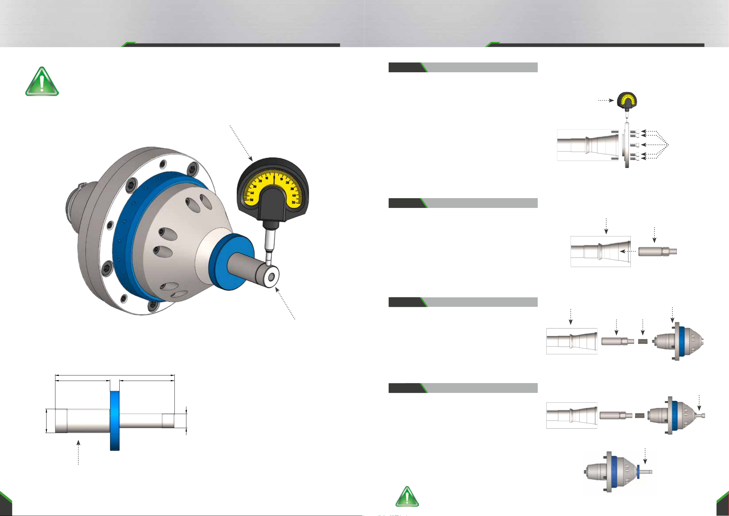
Step 3:
1. Insert the supplied spring into the rear of the chuck.
2. Screw the chuck onto the face contact of the adapter
flange using the supplied mounting screws. When
doing so, please apply the mounting screws only
lightly. (The mounting screws are tightened after the
concentricity adjustment).
Mount chuck
CAUTION: Risk of injury!
Adjusting mandrel
(ISO 2768 -f)
Winkelmaße
- 6
>6-30
>30-120
>120-400
>400-1000
>1000
0,05
0,1
0,15
0,2
0,3
0,5
- 10
>10-50
>50-120
>120-400
>400
1°
30`
20`
10`
5`
Längenmaße
1
F
8
7
6
5
4
3
2
1
8
7
6
5
4
3
2
A
B
C
D
E
F
A
B
C
D
E
Weitergabe sowie Vervielfältigung dieses Dokuments, Verwertung und Mitteilung seines Inhalts sind verboten, soweit nicht ausdrücklich gestattet.
Zuwiderhandlungen verpflichten zu Schadenersatz. Alle Rechte für den Fall der Patent-, Gebrauchsmuster- oder Geschmacksmustereintragung vorbehalten
Schutzvermerk
DIN 34 beachten
GDS
Präzisionszerspanungs GmbH
11
A3
1:2
Material <nicht festgelegt>
16.16
Gewicht (kg):
/
Status
Material:
Blatt / von
Benennung:
Artikelnummer:
Format
Maßstab
Rohabmessung:
DIN 6 T1 -
Proj.methode 1
AR
Name
10.05.2019
Datum
Gepr.
Erstellt
NameDatum
Änderung
Rev
Allgemein-
toleranzen
DIN ISO 2768-mK
Zeichnungsnummer:
Oberflächenbehandlung:
1
F
8
7
6
5
4
3
2
1
8
7
6
5
4
3
2
A
B
C
D
E
F
A
B
C
D
E
Weitergabe sowie Vervielfältigung dieses Dokuments, Verwertung und Mitteilung seines Inhalts sind verboten, soweit nicht ausdrücklich gestattet.
Zuwiderhandlungen verpflichten zu Schadenersatz. Alle Rechte für den Fall der Patent-, Gebrauchsmuster- oder Geschmacksmustereintragung vorbehalten
Backenfutter SHARK
Schutzvermerk
DIN 34 beachten
GDS
Präzisionszerspanungs GmbH
Basisfutter
11
A3
1:1.5
Material <nicht festgelegt>
5.90
Gewicht (kg):
/
Status
Material:
Blatt / von
Benennung:
Artikelnummer:
Format
Maßstab
Rohabmessung:
in Arbeit
DIN 6 T1 -
Proj.methode 1
AR
Name
14.04.2021
Datum
Gepr.
Erstellt
NameDatum
Änderung
Rev
Allgemein-
toleranzen
DIN ISO 2768-mK
Zeichnungsnummer:
020.172.000Z001
Oberflächenbehandlung:
250002905
Machine
spindle
Tension rod
1
2
134
F
E
D
C
B
A
D
C
B
A
Weitergabe sowie Vervielfältigung dieses Dokuments, Verwertung und Mitteilung seines Inhalts sind verboten, soweit nicht ausdrücklich gestattet.
Zuwiderhandlungen verpflichten zu Schadenersatz. Alle Rechte für den Fall der Patent-, Gebrauchsmuster- oder Geschmacksmustereintragung vorbehalten
E
F
4
3
2
Oberflächenbehandlung:
Zeichnungsnummer:
Allgemein-
toleranzen
DIN ISO 2768-mK
Rev
Änderung
Datum Name
Erstellt
Gepr.
Datum
13.04.2021
Name
AR
DIN 6 T1 -
Proj.methode 1
in Arbeit
Rohabmessung:
Maßstab
Format
Artikelnummer:
Benennung:
Blatt / von
Material:
Status
/
Gewicht:
2.97 kg
Material <nicht festgelegt>
1:2
A4
1 1
GDS
Präzisionszerspanungs GmbH
Schutzvermerk
DIN 34 beachten
Shark-Adapter mit Messuhr
Mounting
screws
Dial gauge
(ISO 2768 -f)
Winkelmaße
- 6
>6-30
>30-120
>120-400
>400-1000
>1000
0,05
0,1
0,15
0,2
0,3
0,5
- 10
>10-50
>50-120
>120-400
>400
1°
30`
20`
10`
5`
Längenmaße
1
F
8
7
6
5
4
3
2
1
8
7
6
5
4
3
2
A
B
C
D
E
F
A
B
C
D
E
Weitergabe sowie Vervielfältigung dieses Dokuments, Verwertung und Mitteilung seines Inhalts sind verboten, soweit nicht ausdrücklich gestattet.
Zuwiderhandlungen verpflichten zu Schadenersatz. Alle Rechte für den Fall der Patent-, Gebrauchsmuster- oder Geschmacksmustereintragung vorbehalten
Schutzvermerk
DIN 34 beachten
GDS
Präzisionszerspanungs GmbH
11
A3
1:1
Material <nicht festgelegt>
10.24
Gewicht (kg):
/
Status
Material:
Blatt / von
Benennung:
Artikelnummer:
Format
Maßstab
Rohabmessung:
DIN 6 T1 -
Proj.methode 1
AR
Name
10.05.2019
Datum
Gepr.
Erstellt
NameDatum
Änderung
Rev
Allgemein-
toleranzen
DIN ISO 2768-mK
Zeichnungsnummer:
Oberflächenbehandlung:
Step 1:
1. Make sure that the face of the machine interface is
level and clean.
2. Clean all contact surfaces of the adapter flange.
3. Mount the adapter flange on the machine interface
using the supplied mounting screws.
4. Align the runout of the adapter flange to 0.001mm
by tapping lightly on the alignment surface with the
alignment hammer provided.
5. After achieving the optimum runout, tighten the
mounting screws crosswise to 15 Nm.
Preparation of the adapter flange
Step 2:
1. Screw the tension rod into the machine spindle using
the supplied double socket wrench (11) and tighten it
firmly with the supplied counter screw.
2. Move the tension rod with the machine control to the
rear.
3. Clean all contact surfaces of the adapter flange and
the chuck.
Screw in tension rod
Step 4:
1. Move the tension rod forward with the machine con-
trol.
2. Screw the supplied adjusting screw into the chuck
from the front until a slight resistance is felt.
3. Insert the Ø 12 or Ø 20 adjusting mandrel into the
chuck and adjust the clamping jaws to Ø 12 or Ø 20
with the adjusting screw so that the clearance is the
smallest (see page 6 step 6).
Preparation for adjustment
Commissioning SHARK 5-Jaw Chuck Commissioning SHARK 5-Jaw Chuck
ATTENTION:
The SHARK 5-Jaw Chuck is only
suitable for automatic operation.
Adjustment mandrel
Adjusting mandrel
Dial gauge