8
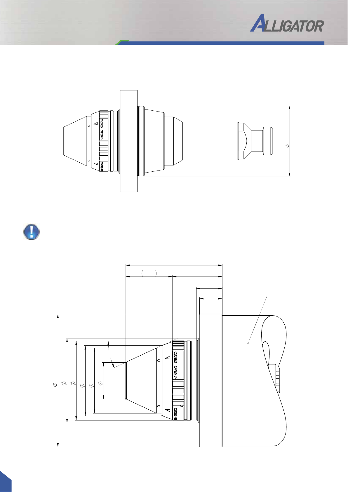
As a result of continuous improvement and further development of our designs, the information and illustrations in this brochure are not binding.
The specifications and installation lengths of the machine manufacturer must be observed. All specifications are in mm. Errors and omissions excepted.
GDS ALLIGATOR
The new ALLIGATOR hydraulic expansion precision clamping system can be used
in the following tool grinding machines:
Accessories for ALLIGATOR:
Intermediate bushings with bayonet locking
for automatic bushing exchange
Item No. Name d
350112403 Intermediate sleeve BJ ø20 x 64 3
350112404 Intermediate sleeve BJ ø20 x 64 4
350112405 Intermediate sleeve BJ ø20 x 64 5
350112406 Intermediate sleeve BJ ø20 x 64 6
350112407 Intermediate sleeve BJ ø20 x 64 7
350112408 Intermediate sleeve BJ ø20 x 64 8
350112409 Intermediate sleeve BJ ø20 x 64 9
350112410 Intermediate sleeve BJ ø20 x 64 10
350112411 Intermediate sleeve BJ ø20 x 64 11
350112412 Intermediate sleeve BJ ø20 x 64 12
350112413 Intermediate sleeve BJ ø20 x 64 13
350112414 Intermediate sleeve BJ ø20 x 64 14
350112415 Intermediate sleeve BJ ø20 x 64 15
350112416 Intermediate sleeve BJ ø20 x 64 16
350112417 Intermediate sleeve BJ ø20 x 64 17
250001590 Mounting wrench D20
250001638 Bayonet insert
Reinecker
Item No.
400002006
ANCA
Item No.
400002002
ISOG
Item No.
400002005
Walter
Item No.
400002001
Saacke
Item No. 400002003
Spindle with union nut
Item No. 400002004
Spindle with flat contact face
Item No. Name d
350111903 Intermediate sleeve RS ø20 3
350111904 Intermediate sleeve RS ø20 4
350111905 Intermediate sleeve RS ø20 5
350111906 Intermediate sleeve RS ø20 6
350111907 Intermediate sleeve RS ø20 7
350111908 Intermediate sleeve RS ø20 8
350111909 Intermediate sleeve RS ø20 9
350111910 Intermediate sleeve RS ø20 10
350111911 Intermediate sleeve RS ø20 11
350111912 Intermediate sleeve RS ø20 12
350111913 Intermediate sleeve RS ø20 13
350111914 Intermediate sleeve RS ø20 14
350111915 Intermediate sleeve RS ø20 15
350111916 Intermediate sleeve RS ø20 16
Intermediate sleeves with radial locking