GDS SHARK Installation guide

Assembly instructions // Instruction manual
grinding deserves SOLUTIONS
SHARK
5-Jaw Chuck
for ANCA machines

2 3
As a result of continuous improvement and further development of our designs, the information and illustrations in this brochure are not binding.
The specifications and installation lengths of the machine manufacturer must be observed. All specifications are in mm. Errors and omissions excepted.
GDS SHARK 5-Jaw Chuck ANCA GDS SHARK 5-Jaw Chuck ANCA interference contour
Case includes:
SHARK 5-Jaw Chuck
SHARK adapter flange
tension rod
Compression spring
Adjusting screw
Adjusting mandrel D20d12
Mounting screws
Clamping wrench SW6x350
Tension wrench SW6x150
Tapper D30x155 Alignment hammer
Double socket wrench SW24 x 27 with handle
SHARK 5-Jaw Chuck for a clamping range of 3-20 mm.
(ISO 2768 -f)
Winkelmaße
- 6
>6-30
>30-120
>120-400
>400-1000
>1000
0,05
0,1
0,15
0,2
0,3
0,5
- 10
>10-50
>50-120
>120-400
>400
1°
30`
20`
10`
5`
Längenmaße
9
32
110
115
148
34,9°
12,5
29,5
49,7
119,4
144
52
105
72,4
110,4
1
F
8
7
6
5
4
3
2
1
8
7
6
5
4
3
2
A
B
C
D
E
F
A
B
C
D
E
Weitergabe sowie Vervielfältigung dieses Dokuments, Verwertung und Mitteilung seines Inhalts sind verboten, soweit nicht ausdrücklich gestattet.
Zuwiderhandlungen verpflichten zu Schadenersatz. Alle Rechte für den Fall der Patent-, Gebrauchsmuster- oder Geschmacksmustereintragung vorbehalten
Backenfutter SHARK
Schutzvermerk
DIN 34 beachten
GDS
Präzisionszerspanungs GmbH
System Walter SK50
11
A3
1:1
Material <nicht festgelegt>
6.70
Gewicht (kg):
/
Status
Material:
Blatt / von
Benennung:
Artikelnummer:
Format
Maßstab
Rohabmessung:
DIN 6 T1 -
Proj.methode 1
LJ
Name
01.04.2021
Datum
Gepr.
Erstellt
NameDatum
Änderung
Rev
Allgemein-
toleranzen
DIN ISO 2768-mK
Zeichnungsnummer:
020.172.000Z100
Oberflächenbehandlung:
400008000
(ISO 2768 -f)
Winkelmaße
- 6
>6-30
>30-120
>120-400
>400-1000
>1000
0,05
0,1
0,15
0,2
0,3
0,5
- 10
>10-50
>50-120
>120-400
>400
1°
30`
20`
10`
5`
Längenmaße
9
12 110,4
70
1
F
8
7
6
5
4
3
2
1
8
7
6
5
4
3
2
A
B
C
D
E
F
A
B
C
D
E
Weitergabe sowie Vervielfältigung dieses Dokuments, Verwertung und Mitteilung seines Inhalts sind verboten, soweit nicht ausdrücklich gestattet.
Zuwiderhandlungen verpflichten zu Schadenersatz. Alle Rechte für den Fall der Patent-, Gebrauchsmuster- oder Geschmacksmustereintragung vorbehalten
Backenfutter SHARK
Schutzvermerk
DIN 34 beachten
GDS
Präzisionszerspanungs GmbH
System Walter SK50
11
A3
1:1
Material <nicht festgelegt>
6.70
Gewicht (kg):
/
Status
Material:
Blatt / von
Benennung:
Artikelnummer:
Format
Maßstab
Rohabmessung:
DIN 6 T1 -
Proj.methode 1
AR
Name
10.05.2019
Datum
Gepr.
Erstellt
NameDatum
Änderung
Rev
Allgemein-
toleranzen
DIN ISO 2768-mK
Zeichnungsnummer:
020.172.000Z100
Oberflächenbehandlung:
400008000
Available for the following machines:
ANCA
Walter
Available for these machines on request:
ISOG
JOERG S-techplus
Reinecker
Saacke
Schütte
Star
TGT
Vollmer
11
1
3
4
5
6
7
2
8
9
10
3
9
42
1
6
10
78
11
5
12
Scan QR codeor for this and other user guides.
Or visit our website at: gds-praezision.de/gebrauchsanleitungen/

4 5
As a result of continuous improvement and further development of our designs, the information and illustrations in this brochure are not binding.
The specifications and installation lengths of the machine manufacturer must be observed. All specifications are in mm. Errors and omissions excepted.
Commissioning SHARK 5-Jaw Chuck ANCA
ATTENTION:
The SHARK 5-Jaw Chuck is only
suitable for automatic operation.
Commissioning SHARK 5-Jaw Chuck ANCA
Adjusting mandrel
Dial gauge
Adjusting mandrel
1. Insert the supplied spring into the rear of the chuck.
2. Screw the chuck onto the face contact of the ad-
apter flange using the supplied mounting screws.
When doing so, please apply the mounting screws
only lightly. (The mounting screws are tightened
after the concentricity adjustment).
Mount chuck
Step 3:
1. Screw the tension rod into the machine spindle
using the supplied double-ended socket wrench
(11).
2. Move the tension rod forward with the machine
control.
3. Measure the control dimension length 55mm from
the plane surface of the machine spindle to the
plane surface of the tension rod.
4. If the dimension 55mm is not reached, remove the
tension rod, loosen the pressure screw and adjust
the determined difference until the dimension
55mm is reached, tighten the pressure screw again.
5. Screw the tension rod into the machine spindle
again and tighten it with the counter screw inside.
Check the control dimension 55mm.
6. Move the tension rod with the machine control to
the rear.
Screw in tension rod
Step 1:
1. Make sure that the face of the machine interface is
level and clean.
2. Clean all contact surfaces of the adapter flange.
3. Mount the adapter flange on the machine interface
using the supplied mounting screws.
4. Align the runout of the adapter flange to 0.001mm
by tapping lightly on the alignment surface with the
alignment hammer provided.
5. After achieving the optimum runout, tighten the
mounting screws crosswise to 15 Nm.
Preparation of the adapter flange
Step 2:
Mounting
screws
Dial gauge
1
2
134
F
E
D
C
B
A
D
C
B
A
Weitergabe sowie Vervielfältigung dieses Dokuments, Verwertung und Mitteilung seines Inhalts sind verboten, soweit nicht ausdrücklich gestattet.
Zuwiderhandlungen verpflichten zu Schadenersatz. Alle Rechte für den Fall der Patent-, Gebrauchsmuster- oder Geschmacksmustereintragung vorbehalten
E
F
4
3
2
Oberflächenbehandlung:
Zeichnungsnummer:
Allgemein-
toleranzen
DIN ISO 2768-mK
Rev
Änderung
Datum Name
Erstellt
Gepr.
Datum
13.04.2021
Name
AR
DIN 6 T1 -
Proj.methode 1
in Arbeit
Rohabmessung:
Maßstab
Format
Artikelnummer:
Benennung:
Blatt / von
Material:
Status
/
Gewicht:
2.97 kg
Material <nicht festgelegt>
1:2
A4
1 1
GDS
Präzisionszerspanungs GmbH
Schutzvermerk
DIN 34 beachten
Shark-Adapter mit Messuhr
(ISO 2768 -f)
Winkelmaße
- 6
>6-30
>30-120
>120-400
>400-1000
>1000
0,05
0,1
0,15
0,2
0,3
0,5
- 10
>10-50
>50-120
>120-400
>400
1°
30`
20`
10`
5`
Längenmaße
1
F
8
7
6
5
4
3
2
1
8
7
6
5
4
3
2
A
B
C
D
E
F
A
B
C
D
E
Weitergabe sowie Vervielfältigung dieses Dokuments, Verwertung und Mitteilung seines Inhalts sind verboten, soweit nicht ausdrücklich gestattet.
Zuwiderhandlungen verpflichten zu Schadenersatz. Alle Rechte für den Fall der Patent-, Gebrauchsmuster- oder Geschmacksmustereintragung vorbehalten
Schutzvermerk
DIN 34 beachten
GDS
Präzisionszerspanungs GmbH
11
A3
1:1
Material <nicht festgelegt>
10.24
Gewicht (kg):
/
Status
Material:
Blatt / von
Benennung:
Artikelnummer:
Format
Maßstab
Rohabmessung:
DIN 6 T1 -
Proj.methode 1
AR
Name
10.05.2019
Datum
Gepr.
Erstellt
NameDatum
Änderung
Rev
Allgemein-
toleranzen
DIN ISO 2768-mK
Zeichnungsnummer:
Oberflächenbehandlung:
(ISO 2768 -f)
Winkelmaße
- 6
>6-30
>30-120
>120-400
>400-1000
>1000
0,05
0,1
0,15
0,2
0,3
0,5
- 10
>10-50
>50-120
>120-400
>400
1°
30`
20`
10`
5`
Längenmaße
1
F
8
7
6
5
4
3
2
1
8
7
6
5
4
3
2
A
B
C
D
E
F
A
B
C
D
E
Weitergabe sowie Vervielfältigung dieses Dokuments, Verwertung und Mitteilung seines Inhalts sind verboten, soweit nicht ausdrücklich gestattet.
Zuwiderhandlungen verpflichten zu Schadenersatz. Alle Rechte für den Fall der Patent-, Gebrauchsmuster- oder Geschmacksmustereintragung vorbehalten
Schutzvermerk
DIN 34 beachten
GDS
Präzisionszerspanungs GmbH
11
A3
1:2
Material <nicht festgelegt>
16.16
Gewicht (kg):
/
Status
Material:
Blatt / von
Benennung:
Artikelnummer:
Format
Maßstab
Rohabmessung:
DIN 6 T1 -
Proj.methode 1
AR
Name
10.05.2019
Datum
Gepr.
Erstellt
NameDatum
Änderung
Rev
Allgemein-
toleranzen
DIN ISO 2768-mK
Zeichnungsnummer:
Oberflächenbehandlung:
Machine
spindle
Tension rod
(ISO 2768 -f)
Winkelmaße
- 6
>6-30
>30-120
>120-400
>400-1000
>1000
0,05
0,1
0,15
0,2
0,3
0,5
- 10
>10-50
>50-120
>120-400
>400
1°
30`
20`
10`
5`
Längenmaße
1
F
8
7
6
5
4
3
2
1
8
7
6
5
4
3
2
A
B
C
D
E
F
A
B
C
D
E
Weitergabe sowie Vervielfältigung dieses Dokuments, Verwertung und Mitteilung seines Inhalts sind verboten, soweit nicht ausdrücklich gestattet.
Zuwiderhandlungen verpflichten zu Schadenersatz. Alle Rechte für den Fall der Patent-, Gebrauchsmuster- oder Geschmacksmustereintragung vorbehalten
Schutzvermerk
DIN 34 beachten
GDS
Präzisionszerspanungs GmbH
11
A3
1:2
Material <nicht festgelegt>
16.16
Gewicht (kg):
/
Status
Material:
Blatt / von
Benennung:
Artikelnummer:
Format
Maßstab
Rohabmessung:
DIN 6 T1 -
Proj.methode 1
AR
Name
10.05.2019
Datum
Gepr.
Erstellt
NameDatum
Änderung
Rev
Allgemein-
toleranzen
DIN ISO 2768-mK
Zeichnungsnummer:
Oberflächenbehandlung:
1
F
8
7
6
5
4
3
2
1
8
7
6
5
4
3
2
A
B
C
D
E
F
A
B
C
D
E
Weitergabe sowie Vervielfältigung dieses Dokuments, Verwertung und Mitteilung seines Inhalts sind verboten, soweit nicht ausdrücklich gestattet.
Zuwiderhandlungen verpflichten zu Schadenersatz. Alle Rechte für den Fall der Patent-, Gebrauchsmuster- oder Geschmacksmustereintragung vorbehalten
Backenfutter SHARK
Schutzvermerk
DIN 34 beachten
GDS
Präzisionszerspanungs GmbH
Basisfutter
11
A3
1:1.5
Material <nicht festgelegt>
5.90
Gewicht (kg):
/
Status
Material:
Blatt / von
Benennung:
Artikelnummer:
Format
Maßstab
Rohabmessung:
in Arbeit
DIN 6 T1 -
Proj.methode 1
AR
Name
14.04.2021
Datum
Gepr.
Erstellt
NameDatum
Änderung
Rev
Allgemein-
toleranzen
DIN ISO 2768-mK
Zeichnungsnummer:
020.172.000Z001
Oberflächenbehandlung:
250002905
SpringTension rod
Mounting screw
Machine
spindle
55
Präzisionszerspanungs GmbH
SHARK-Zugstange in ANCA-Spindel
Stand 07.2021

6 7
As a result of continuous improvement and further development of our designs, the information and illustrations in this brochure are not binding.
The specifications and installation lengths of the machine manufacturer must be observed. All specifications are in mm. Errors and omissions excepted.
Commissioning SHARK 5-Jaw Chuck ANCA GDS SHARK ANCA Safety // Sources of error
GDS SHARK error causes and solutions
Please note:
• The SHARK multi-range clamping system was designed for loading and changing rotationally
symmetrical blanks and tools in automatic mode.
• For shank tools, all shanks according to DIN 1835 Form A, B, E or DIN 6535 form HA, HB, HE
can be clamped.
• The SHARK multi-range clamping system may only be used within the scope of its technical
data. within the scope of its technical data.
• This product is intended for industrial use.
• Intended use includes compliance with all the information in these instructions.
• Faultless function and warranty claims can only be guaranteed with original GDS accessories.
• Inserting the blank by hand is prohibited.
GDS SHARK safety instructions
Check the following points:
• Check clamping pressure
• Check blank
• Contamination
• All mounting screws correctly tightened
• Chuck requires room temperature
• Open everything again, clean and start from the beginning step by step
Set clamping range
Step 6:
1. You can set the desired clamping range by adjusting
the adjusting screw.
Adjust concentricity
Step 5:
Align the concentricity by tapping on the alignment
surface with the alignment hammer (9) supplied.
1. Turn the A-axis evenly clockwise to the highest
clock deflection value. Now reduce this by half the
value by tapping.
2. Repeat this process until you have achieved a run-
out of 0.001mm. Then tighten the mounting screws
crosswise with 15Nm.
3. Unclamp and clamp the adjusting mandrel three to
five times so that the chuck settles and the assem-
bly tensions are released.
4. Check the concentricity again. Readjust if necessary.
ATTENTION:
To ensure proper functioning, disassemble
and clean the chuck at least once a month.
When adjusting, use precision dial gauges
as well as the adjusting mandrel supplied.
Setting concentricity and repeatability
Please take the time to adjust the runout. The more accurately the chuck is set during setup, the more accurately it
will behave.
Alignment surface
CAUTION: Risk of injury!
1. Move the tension rod forward with the machine
control.
2. Screw the supplied adjusting screw into the chuck
from the front until a slight resistance is felt.
3. Insert the Ø 12 or Ø 20 adjusting mandrel into the
chuck and adjust the clamping jaws to Ø 12 or Ø 20
with the adjusting screw so that the clearance is the
smallest (see page 7 step 6).
Step 4: Preparation for setting
Clamping range Blank
Ø3mm - Ø8mm Ø8mm
Ø8mm - Ø13mm Ø13mm
Ø13mm - Ø18mm Ø18mm
Ø18mm - Ø20mm Ø20mm
Adjusting mandrel
1
F
8
7
6
5
4
3
2
1
8
7
6
5
4
3
2
A
B
C
D
E
F
A
B
C
D
E
Weitergabe sowie Vervielfältigung dieses Dokuments, Verwertung und Mitteilung seines Inhalts sind verboten, soweit nicht ausdrücklich gestattet.
Zuwiderhandlungen verpflichten zu Schadenersatz. Alle Rechte für den Fall der Patent-, Gebrauchsmuster- oder Geschmacksmustereintragung vorbehalten
Backenfutter SHARK
Schutzvermerk
DIN 34 beachten
GDS
Präzisionszerspanungs GmbH
Basisfutter
11
A3
1:1.5
Material <nicht festgelegt>
5.90
Gewicht (kg):
/
Status
Material:
Blatt / von
Benennung:
Artikelnummer:
Format
Maßstab
Rohabmessung:
in Arbeit
DIN 6 T1 -
Proj.methode 1
AR
Name
14.04.2021
Datum
Gepr.
Erstellt
NameDatum
Änderung
Rev
Allgemein-
toleranzen
DIN ISO 2768-mK
Zeichnungsnummer:
020.172.000Z001
Oberflächenbehandlung:
250002905
Adjusting
screw
(ISO 2768 -f)
Winkelmaße
- 6
>6-30
>30-120
>120-400
>400-1000
>1000
0,05
0,1
0,15
0,2
0,3
0,5
- 10
>10-50
>50-120
>120-400
>400
1°
30`
20`
10`
5`
Längenmaße
1
F
8
7
6
5
4
3
2
1
8
7
6
5
4
3
2
A
B
C
D
E
F
A
B
C
D
E
Weitergabe sowie Vervielfältigung dieses Dokuments, Verwertung und Mitteilung seines Inhalts sind verboten, soweit nicht ausdrücklich gestattet.
Zuwiderhandlungen verpflichten zu Schadenersatz. Alle Rechte für den Fall der Patent-, Gebrauchsmuster- oder Geschmacksmustereintragung vorbehalten
Schutzvermerk
DIN 34 beachten
GDS
Präzisionszerspanungs GmbH
11
A3
1:2
Material <nicht festgelegt>
16.16
Gewicht (kg):
/
Status
Material:
Blatt / von
Benennung:
Artikelnummer:
Format
Maßstab
Rohabmessung:
DIN 6 T1 -
Proj.methode 1
AR
Name
10.05.2019
Datum
Gepr.
Erstellt
NameDatum
Änderung
Rev
Allgemein-
toleranzen
DIN ISO 2768-mK
Zeichnungsnummer:
Oberflächenbehandlung:

8 9
As a result of continuous improvement and further development of our designs, the information and illustrations in this brochure are not binding.
The specifications and installation lengths of the machine manufacturer must be observed. All specifications are in mm. Errors and omissions excepted.
GDS SHARK ANCA basic safety instructions
Basic safety instructions
Danger to persons and property may arise from this product due to incorrect handling, assembly
and maintenance if these operating instructions are not observed. Damage and defects must be
reported to the manufacturer immediately and repaired without delay in order to keep the extent of
damage to a minimum and to ensure that the safety of the product is not impaired.
Only original GDS spare parts may be used.
Notes on special hazards
Danger to persons (risk of injury) and damage to property can arise from the SHARK 5-Jaw Chuck
system if:
• it is not used as intended;
• it is improperly installed or maintained;
• the safety and assembly instructions, the safety and accident prevention regulations applicable
at the place of use and the EC Machinery Directive are not observed.
Use not in accordance with the intended purpose
The multi-range chuck must not be used for turning or milling. The precision grinding chuck is not
being used for the intended purpose, for example:
• if tools are not properly clamped.
• if, in disregard of the safety regulations, persons are working on the 5-jaw chuck without additi-
onal protective devices, e.g. in order to machine clamped tools.
• the technical data are exceeded when using the 5-jaw chuck.
• the 5-jaw chuck is used for machines not intended for this purpose.
Intended use
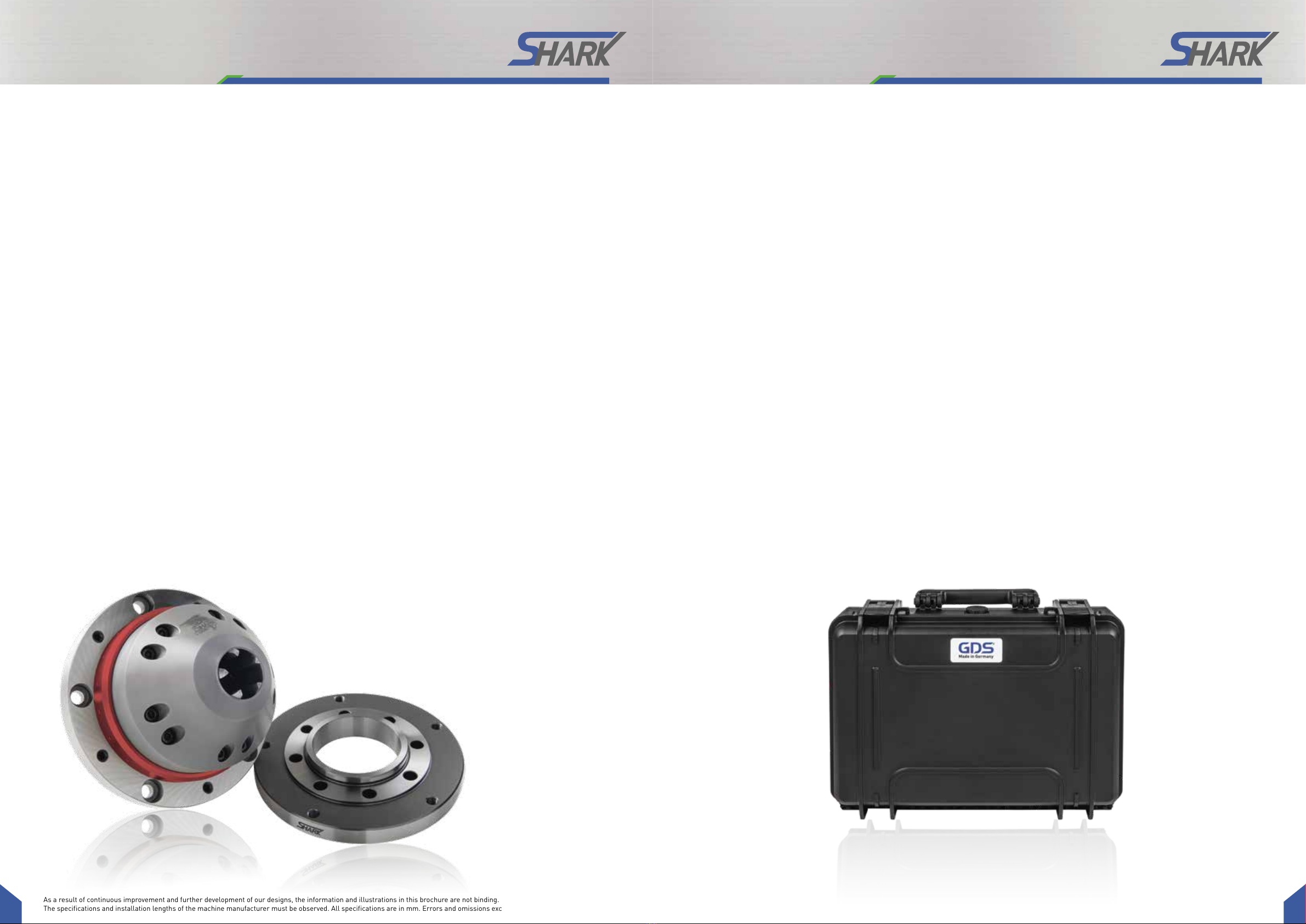
The SHARK 5-Jaw Chuck is used for clamping tools with cylindrical shanks for tool grinding on
grinding machines.
• The product may only be used within the scope of its technical data.
• The product is intended for installation in a machine. The applicable directives must be observed
and complied with.
• The product is intended for industrial use.
• Intended use also includes compliance with all the information in these instructions.
CAUTION:
Risk of injury to the operating personnel in case of jaw breakage or loss of work-
piece due to flying parts!
• When using the 5-jaw chuck, protective equipment must be used in accordance
with the EC Machinery Directive so that in the event of failure of the 5-jaw chuck or a
component of the chuck, parts flying away are caught by the protective equipment.
• The machine manufacturer must ensure sufficient wall thicknesses for his enclo-
sure/protective equipment (in compliance with the currently applicable regulati-
ons and standards).
GDS SHARK ANCA basic safety instructions
CAUTION:
Risk of injury to the operating personnel in case of improper use and exceeding the
technical data due to failure of the 5-jaw chuck! Improper use and exceeding the
technical data may cause failure of the 5-jaw chuck, resulting in danger to life and
limb of the operator and considerable damage to the equipment.
• Observe the values of the technical data
• Only use the 5-jaw chuck for its intended purpose.
• Comply with the applicable safety standards and safety regulations.
CAUTION:
Risk of injury due to falling down of the multigange clamping system during trans-
port, mounting and dismounting. Protect the 5-jaw chuck from falling down during
transport and installation or dismantling.
CAUTION:
During manual loading and unloading, there is a risk of crushing limbs due to ope-
ning and closing of the clamping jaws. Do not reach between the clamping jaws. For
hand-loaded machines, the tool feed must be carried out via a setting aid.
CAUTION:
Risk of injury during manual loading and unloading of the tools due to sharp cutting
edges. Remove the tools only when the machine is at a standstill. Prefer an automa-
tic loading and unloading of the tools.

10 11
As a result of continuous improvement and further development of our designs, the information and illustrations in this brochure are not binding.
The specifications and installation lengths of the machine manufacturer must be observed. All specifications are in mm. Errors and omissions excepted.
GDS SHARK ANCA basic safety instructions GDS SHARK ANCA Set up
Note for safe operation
• Cylindrical tools with an outer diameter of at least 3 mm can be clamped as the smallest tool. If
smaller tools are clamped, they cannot be clamped safely.
• With manual loading, there is a risk that limbs can be trapped and crushed. Therefore, an inser-
tion aid must be used for manual loading.
• Out-of-round tools damage the 5-jaw chuck or have an unfavorable effect on the grinding accuracy.
The concentricity of the tools must not exceed 0.006 mm.
• The chuck must not be used in EDM machines. Corrosion can cause the 5-jaw chuck to lose its
specification.
• Observe the maintenance and care instructions.
Function test
After the 5-jaw chuck has been set up, its function must be checked by commissioning. If the
clamping device is changed, it is necessary to adjust the 5-jaw chuck to the new situation with a
new stroke check.
Mounting the 5-jaw chuck
The 5-jaw chuck and the associated actuating device must be matched to each other. The stroke of
the chuck must be sufficient to safely accommodate the largest and smallest diameter to be clamped.
When mounting the chuck and the clamping cylinder on the grinding machines, the following safety
requirements must be observed:
• The machine spindle must not start until the clamping pressure is built up in the clamping cylinder
and the clamping takes place in the permissible working range and the machine door is closed.
• It must not be possible to release the tension until the machine spindle has come to a standstill.
• If the clamping energy fails, the tool must remain firmly clamped until the spindle comes to a
standstill.
• In the event of power failure and return, there must be no change in the current switching position.
• The axial movement of the drive cylinder must not exceed a speed of 10 mm/sec when loaded
manually.
Clamping depth
The clamping depth depends on the clamping diameter.
The minimum clamping depth for optimum concentricity is 2.5 x D clamping diameter.
Adjusting the clamping range
You can set the desired clamping range by adjusting the adjusting screw (see page 6 step 6).

GDS Präzisionszerspanungs GmbH
Endelbergstrasse 8
D - 72131 Ofterdingen
Telefon: + 49 (0) 74 73 - 27 26 72
Telefax: + 49 (0) 74 73 - 27 26 49
Email: [email protected]
Web: www.gds-praezision.de
Table of contents
Other GDS Industrial Equipment manuals
Popular Industrial Equipment manuals by other brands

Swisher
Swisher 22080 owner's manual

Guttermaster
Guttermaster Pro Curved Pole user guide

Grundfos
Grundfos CIM 200 Functional profile and user manual

Reliable
Reliable N2-Blast DDX Instructions for installation, operation care and maintenance

KLINGER
KLINGER KHD-SGF Installation, operation & maintenance manual

EWS
EWS TS Series operating instructions