4
Installation
The unit should be mounted in a position which is accessible and in the field of vision. Mains should
be from a fused supply (2A) and connected to the mains input terminals of the power supply unit.
The vent port should be piped to atmosphere without reduction. This will prevent possible back
pressure affecting the sensor reading.
A minimum of two intake modules should be located within the target area, their position will
be depedant upon the type of gas to be monitored and its density with respect to air.
Heavy gases (LPG, Propane, Butane, Refrigerant Gases) – locate at 15 to 20 cm from the floor.
Lighter gases (Methane, Natural Gas, Town Gas) – locate at 5 to 10 cm from the ceiling.
Carbon Monoxide – locate at 1.5 to 2 metres from floor level.
The control panel should be mounted away from direct heat.
Operation
On power up the green power indicator will flash for 60 seconds indicating that the system is
stabilising. During this period all alarms are held in the off position.
After the stabilisation period any gas detected by the sensor will be indicated on the display, with
any alarm level being exceeded resulting in the sounder and appropriate red alarm LED and relay
activating.
Pressing the reset pad will result in the sounder being silenced. Alarm indicators and relays may
only be reset when the indicated gas level has reduced to below that of the alarm trip points.
A reduced power mode feature is activated one hour after any operator activity. This state is
indicated by a screen power reduction of approximately 50%. Pressing any button will return the
screen to full display.
4-20
OV
Lo
Hi
24V
NO C
AL3
NC NO C
NCNO C
AL2
NCNO C
AL1
NC
W
+
Y
sig
P
-
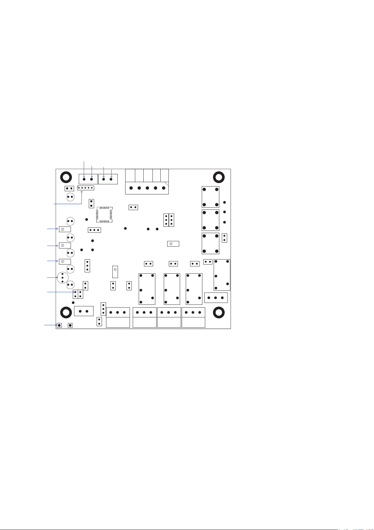
SENSOR FAULT
+ -
4-20mA
Output
PC comms via
hyperterminal
Sensor
Voltage
test pins
Zero LED
4mA
J28
20mA
Zero
Gain
J3
J29
J11
J18 J17 J16
J15
J19
J1
TP3
A B
A
B
A
B
TP11
TP12
TP6TP7
TP13
TP8 TP9 TP2
TP4
TP1
Contrast
J6
J20
J5
J4 J7
J12
J13 J14
J8
J8
x fault
Inhibit Ov 24v J1 CANbus – EOL – see Combi
J4/7 For Semiconductor sensors
J5/11 Sensor (B-catalytic A-4~20mA)
J6/20 Sink/Source 4~20mA output
J8 Gain – factory set
J9 Normally fitted 4~20mA out
J12 Bridge fault enable fit for catalytic sensor
J13 See J8
J14 Sensor supply selector
A for catalytic sensor
B for 4~20mA sensor
J15 Sounder mute
J16 N/E - A1 relay link on
J17 N/E - A2 relay link on
J18 N/E - A3 relay link on
J19 N/E - fault relay link on
J28 Reset processor
J29 Address change enable – see Combi
A
B
4~20mA In
Sensor
supply
adjust
4~20mA
Output
Fig 2