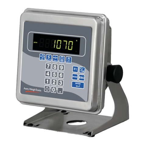
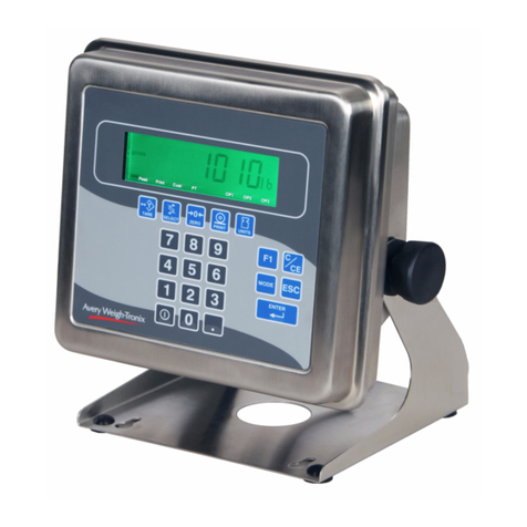
Avery Weigh-Tronix E1070 User manual

Model E1070
Indicator
Service Manual
NORTH AMERICA
AWT35-500106 Issue AF March 2010

© Avery Weigh-Tronix, LLC 2010. All rights reserved.
No part of this publication may be reproduced, stored in an electronic retrieval system, or transmitted in any form
or by any means, electronic, mechanical, photocopying, recording or otherwise without the prior written consent of
the copyright owner, or as permitted by law or under license. Full acknowledgment of the source must be given.
Avery Weigh-Tronix is a registered trade mark of the Avery Weigh-Tronix, LLC. This publication was correct at the
time of going to print however, Avery Weigh-Tronix, LLC reserves the right to alter without notice the specification,
design, price or conditions of supply of any product or service at any time.
All third party brands and product names used within this document are trademarks or registered trademarks of
their respective holders.
E1070_rev2006_s_en_500106.book

E1070 Indicator Service Manual 3
Table of Contents
page
Manual revision history ............................................................................................................................. 5
Chapter 1 General information and warnings ......................................................................................... 7
About this manual ..............................................................................................................7
Text conventions ......................................................................................................... 7
Special messages ....................................................................................................... 7
Installation .......................................................................................................................... 8
Electrical installation .......................................................................................................... 8
Pluggable equipment ................................................................................................... 8
Permanently wired equipment - Isolator requirements ................................................ 8
Safe handling of equipment with batteries .................................................................. 9
Wet conditions ............................................................................................................. 9
Routine maintenance ......................................................................................................... 9
Cleaning the machine ...................................................................................................... 10
Training ............................................................................................................................ 10
Sharp objects ................................................................................................................... 10
FCC and EMC declarations of compliance ...................................................................... 11
Chapter 2 Introduction ............................................................................................................................ 12
Front Panel ...................................................................................................................... 12
Keys .......................................................................................................................... 12
Annunciators ............................................................................................................. 15
Error Messages ................................................................................................................ 16
Chapter 3 Using the Menus .................................................................................................................... 18
Available Menus ............................................................................................................... 18
User menu (password is 111) ................................................................................... 18
Service menu (password is 0701) ............................................................................. 18
Supervisor menu (password is 1793) ........................................................................ 18
Accessing the Menus ....................................................................................................... 19
User Menu ....................................................................................................................... 20
Service Menu ...................................................................................................................23
CAL Submenu for Analog Scales .............................................................................. 24
SCALE submenu ....................................................................................................... 28
APP submenu ........................................................................................................... 41
Extra Info: Print Format Editing ................................................................................. 47
Thermal Labels Print Formats ................................................................................... 50
SERIAL submenu ...................................................................................................... 54
TEST submenu ......................................................................................................... 65
AUDIT submenu ........................................................................................................ 70
INPUT submenu ........................................................................................................ 71
OUTPUT submenu .................................................................................................... 72
OPTION submenu ..................................................................................................... 74
Supervisor Menu ............................................................................................................ 109
HOUR (Set time) ..................................................................................................... 111
SETUP (Setup menu) .............................................................................................. 111
TEST (Test menu) ................................................................................................... 127
AUDIT (Audit counters) menu ................................................................................ 131
Chapter 4 SensorComm Hardware Configuration and Calibration ................................................... 132
Introduction .................................................................................................................... 132
Enable SensorComm ..................................................................................................... 132

4 E1070 Indicator Service Manual
Enable/Configure Weigh-Bars ....................................................................................... 133
CAL submenu for SensorComm scales ......................................................................... 134
CORNER (SensorComm Cornering) ....................................................................... 134
GHOST (Ghost Calibration Factors) ....................................................................... 135
Chapter 5 SensorComm Error Messages ............................................................................................ 137
Chapter 6 Remote Display Functionality ............................................................................................. 138
Remote Display Modes: (Application Settings – Remote Indicator) .............................. 138
Mode 1: Remote weight display only ....................................................................... 138
Mode 2: Remote weight display with annunciators ................................................. 138
Mode 3: Remote weight display with keypad .......................................................... 138
Mode 4: Remote weight display with keypad and annunciators .............................. 139
Remote Display Modes: (Serial Port Settings – Host Indicator) .................................... 139
Mode 4100: Remote weight display only ................................................................. 139
Mode 1: Remote weight display only ....................................................................... 139
Mode 2: Remote weight display with annunciators ................................................. 139
Mode 3: Remote weight display with keypad. ......................................................... 140
Mode 4: Remote display with keypad and annunciators. ........................................ 140
Communications Timeout: ............................................................................................. 141
Chapter 7 Mainboard Network LED Diagnostics ................................................................................ 142
Chapter 8 Network Connections .......................................................................................................... 143
Default network settings feature .................................................................................... 144
General Description: ................................................................................................ 144
Fieldbus #1 default values: ...................................................................................... 144
Fieldbus #2 default values: ...................................................................................... 145
UPD indicator Discovery ................................................................................................ 145
General Description ................................................................................................. 145
Protocol: .................................................................................................................. 145
Chapter 9 Ethernet Industrial Protocols .............................................................................................. 147
Ethernet IP Explicit Messaging ...................................................................................... 147
AWTX Input Point Object (Data Out) ....................................................................... 147
AWTX Output Point Object (Data In) ....................................................................... 147
Ethernet IP Implicit Messaging ...................................................................................... 148
AWTX Assembly Instance for PLC Configuration ................................................... 148
ModBus/TCP .................................................................................................................. 148
Starting Register Locations for PLC Configuration .................................................. 148
Chapter 10 Complete Menu Structures ............................................................................................... 149
Complete Supervisor and User Menus .......................................................................... 149
Complete Service Menu ................................................................................................. 150
Chapter 11 E1070 Technical Illustrations ............................................................................................ 151
Enclosure Parts and Assembly ...................................................................................... 151
Enclosure Parts and Assembly ...................................................................................... 152
Wall Mount Application .................................................................................................. 153
System Block Diagram ................................................................................................... 154
Keypad & Schematic and Power Supply Bd. P/N 60071-0016 ...................................... 155
Main Board Assembly 57643-0011 ............................................................................... 156
Optional PC Boards ....................................................................................................... 157
I/O External Calbe Identification Pin-outs ...................................................................... 158
Trips Interface Unit (TIU3) (optional) & Assembly ......................................................... 159
Model E1070 Checkweigher (Low Capacity) ................................................................. 160
Model E1070 Checkweigher (Medium Capacity) ........................................................... 161
E1070 Service Manual 5
Manual revision history
Current
Issue Date Created Details of Changes
AC March 2008 Added checkweigher drawings in zfolds. Added information to the remote IO section of the
OPTION menu. Many other small changes. Added note to main board assy drawing about
Current Loop and jumpering P5. Reformatted to new AWT template.
AD July 2008 Added note stating that 56133-0010 may be substituted for 57042-0018 to p. 144 (ZFOLDS)
Changed PN 53984-0058 to AWT25-000674 on page 153. Changed note on page 150 about P-9
jumper. Added Explicit Message Chapter 9.
AE January 2010 Updates to SCALE menu. GTU added to print tokens. Other small changes.
AF March 2010 Added note at top of page 50 on default print format file. Also fixed a dimension on a label on the
same page. Per RFC-501164.

6 E1070 Service Manual

E1070 Service Manual 7
1.1 About this manual
1 General information and warnings
1.1 About this manual
This manual is divided into chapters by the chapter number and the large text at the top
of a page. Subsections are labeled as shown by the 1 and 1.1 headings shown above.
The names of the chapter and the next subsection level appear at the top of alternating
pages of the manual to remind you of where you are in the manual. The manual name
and page numbers appear at the bottom of the pages.
1.1.1 Text conventions
Key names are shown in bold and reflect the case of the key being described. This
applies to hard keys and onscreen or soft keys.
Displayed messages appear in bold italic type and reflect the case of the displayed
message.
1.1.2 Special messages
Examples of special messages you will see in this manual are defined below. The
signal words have specific meanings to alert you to additional information or the relative
level of hazard.
DANGER!
THIS IS A DANGER SYMBOL.
DANGER MEANS THAT FAILURE TO FOLLOW SPECIFIC PRACTICES
OR PROCEDURES WILL CAUSE INJURY OR DEATH.
ELECTRICAL WARNING!
THIS IS AN ELECTRICAL WARNING SYMBOL.
ELECTRICAL WARNINGS MEAN THAT FAILURE TO FOLLOW
SPECIFIC PRACTICES OR PROCEDURES MAY RESULT IN
ELECTROCUTION, ARC BURNS, EXPLOSIONS OR OTHER HAZARDS
THAT MAY CAUSE INJURY OR DEATH.
WARNING!
This is a Warning symbol.
Warnings mean that failure to follow specific practices and procedures may
have major consequences such as injury or death.
CAUTION!
This is a Caution symbol.
Cautions give information about procedures that, if not observed, could result
in damage to equipment or corruption to and loss of data.

8 E1070 Service Manual
1 General information and warnings
1.2 Installation
1.3 Electrical installation
1.3.1 Pluggable equipment
Pluggable equipment must be installed near an easily accessible socket outlet.
1.3.2 Permanently wired equipment - Isolator requirements
Permanently connected equipment must have a readily accessible disconnect device
incorporated in the fixed wiring such as an isolator or circuit breaker with at least 3mm
contact separation.
The isolator MUST NOT be installed into the flexible power cable supplied with the unit.
NOTE: This is a Note symbol. Notes give additional and important information, hints
and tips that help you to use your product.
DANGER: RISK OF ELECTRICAL SHOCK. NO USER SERVICEABLE
PARTS. REFER TO QUALIFIED SERVICE PERSONNEL FOR SERVICE.
CAUTION: The power cable must be connected to an earth-grounded electrical
outlet. The electrical supply must have a circuit breaker with an appropriate
rating to protect from over-current conditions.
For your protection, all electrical (110V or 230V) equipment used out of doors or
in wet or damp conditions should be supplied from a correctly fused power
source and protected by an approved ground fault protection device (RCD,
GFCI etc.)
IF IN DOUBT SEEK ADVICE FROM A QUALIFIED ELECTRICIAN.

E1070 Service Manual 9
1.4 Routine maintenance
1.3.3 Safe handling of equipment with batteries
1.3.4 Wet conditions
Under wet conditions, the plug must be connected to the final branch circuit via an
appropriate socket / receptacle designed for washdown use.
Installations within the USA should use a cover that meets NEMA 3R specifications
as required by the National Electrical Code under section 410-57. This allows the unit
to be plugged in with a rain tight cover fitted over the plug.
Installations within Europe must use a socket which provides a minimum of IP56
protection to the plug / cable assembly. Care must be taken to make sure that the
degree of protection provided by the socket is suitable for the environment.
1.4 Routine maintenance
Always turn off the machine and isolate from the power supply before starting any
routine maintenance to avoid the possibility of electric shock.
Make sure that it is placed securely on a flat and level surface.
CAUTION: Danger of explosion if battery is incorrectly replaced. Replace only
with the same or equivalent type recommended by the manufacturer. Dispose
of used batteries according to the manufacturer’s instructions.
ATTENTION: Il y a danger d'explosion s'il y a remplacement incorrect de la
batterie, remplacer uniquement avec une batterie du même type ou d'un type
équivalent recommandé par le constructeur. Mettre au rebut les batteries
usagées conformément aux instructions du fabricant.
IMPORTANT: This equipment must be routinely checked for proper operation
and calibration.
Application and usage will determine the frequency of calibration required for
safe operation.

10 E1070 Service Manual
1 General information and warnings
1.5 Cleaning the machine
1.6 Training
Do not attempt to operate or complete any procedure on a machine unless you have
received the appropriate training or read the instruction books.
To avoid the risk of RSI (Repetitive Strain Injury), place the machine on a surface which
is ergonomically satisfactory to the user. Take frequent breaks during prolonged usage.
1.7 Sharp objects
Do not use sharp objects such as screwdrivers or long fingernails to operate the keys.
Table 1.1 Cleaning DOs and DON’Ts
DO DO NOT
Wipe down the outside of standard products
with a clean cloth, moistened with water and
a small amount of mild detergent
Attempt to clean the inside of the machine
Use harsh abrasives, solvents, scouring cleaners or
alkaline cleaning solutions
Spray the cloth when using a proprietary
cleaning fluid
Spray any liquid directly on to the display windows

E1070 Service Manual 11
1.8 FCC and EMC declarations of compliance
United States
Canada
European Countries
This equipment has been tested and found to comply with the limits for a Class A digital device, pursuant to Part 15 of the FCC Rules.
These limits are designed to provide reasonable protection against harmful interference when the equipment is operated in a
commercial environment. This equipment generates, uses, and can radiate radio frequency energy and, if not installed and used in
accordance with the instruction manual, may cause harmful interference to radio communications. Operation of this equipment in a
residential area is likely to cause harmful interference in which case the user will be required to correct the interference at his own
expense.
This digital apparatus does not exceed the Class A limits for radio noise emissions from digital apparatus set out in the Radio
Interference Regulations of the Canadian Department of Communications.
Le présent appareil numérique n’émet pas de bruits radioélectriques dépassant les limites applicables aux appareils numériques de
la Classe A prescrites dans le Règlement sur le brouillage radioélectrique edicté par le ministère des Communications du Canada.
WARNING: This is a Class A product. In a domestic environment, this product may cause radio interference in which the user may be
required to take adequate measures.

12 E1070 Service Manual
2 Introduction
2 Introduction
This manual covers the information you need to configure and service your Model
E1070 Indicator.
2.1 Front Panel
The front panel, shown in Figure 2.1, consists of the keys and display.
Figure 2.1 E1070 front panel
2.1.1 Keys
The functions of the keys on the front panel are listed on the following pages.

E1070 Service Manual 13
2.1 Front Panel
IMPORTANT: Plug the Model E1070 into properly grounded socket-outlet of the
correct voltage, installed near the equipment and easily accessible. Never use the
unit without an appropriate earthground connection.
Any computer based system should have a separate, grounded power circuit. We
recommend one for the Model E1070.
See the System Block Diagram or Main Board Assembly pages in the technical
illustrations at the back of this manual for wiring instructions.
Never press a key with anything but your finger. Damage to the overlay may result if
sharp or rough objects are used.
Press the TARE key to perform a tare function. Also acts as a left arrow key when in the menu
structure.
Press the SELECT key to toggle between Gross, Tare, Net, Count, Gross Accumulator, Net
Accumulator, Transaction Counter, Piece Weight, and Peak. Dependent on the current application.
Press and hold to access the cutoffs (trips) menu. Also acts as an up arrow key when in the menu
structure.
Press the ZERO key to zero the display.
Press the PRINT key to send information to a peripheral device through one of the Comm ports.
Also acts as a down arrow key when in the menu structure.
Press the UNITS key to scroll through the available units of measure while in normal operating
mode. Also acts as a right arrow key when in the menu structure.
Press the F1 key to select application specific choices. Also used to access PLU memory channels.

14 E1070 Service Manual
2 Introduction
Press the C/CE key to clear entries.
Press the MODE key to scroll through the activated applications. Press and hold for 3-5 seconds to
see the name of the currently active application.
Press the ESC key to escape, or abort, a function or return to normal operation mode.
Press the ENTER key to accept displayed choices.
Press and release the ON/OFF key to turn the unit on. Press and hold the key until the unit turns off.
Use the numeric keypad to enter values.

E1070 Service Manual 15
2.1 Front Panel
2.1.2 Annunciators
There are several annunciators around the edge of the display. The illustration below
explains each one.
Center of Zero Lights when weight on the scale is within the zero range
Motion Lights during scale motion.
Gross Lights when gross weight is displayed
Net Lights when net weight is displayed
Tare Lights when tare weight is displayed
Print Lights when print format sent through serial port
OP 1 Lights when output one is activated
OP 2 Lights when output two is activated
OP 3 Lights when output three is activated
PT Lights when preset tare is active
Network & SensorComm
Status
This is a configurable light to show status of the Network 1, Network 2 or
SensorComm. See note at the bottom of this page.
Accumulator, Count Lights when an accumulation occurs and while in the count and peak
applications
Custom Unit Lights when a custom unit of measure is active
KG Lights when kilograms is the active unit of measure
LB Lights when pounds is the active unit of measure
Checkweigher Lights when checkweighing application is active
Bottom LED color when configured for:
SCOM (SensorComm):
Red – a cell has been ghosted. Check the ghost log.
Green – a sensorcomm error has occurred. Print the error log.
Off – Scale is functioning normally.
Network 1 or 2:
Red – A network error has occurred. Check the network settings on the indicator and
PLC, and reboot the indicator.
Green – The network connection has been established.
Amber – The network is ready for a connection, but no connection has been
established.

16 E1070 Service Manual
2 Introduction
2.2 Error Messages
The following are displayed messages you may see if problems occur or if invalid
operations are attempted with your indicator:
When you are in the Linearity menu item in the Service menu, you may see the
following errors:.
Display Description
Overrange weight. Scale is overloaded.
Underrange weight. Scale is underloaded.
The unit cannot perform a function. Displayed only while key is held down.
Displayed while a key is pressed when attempting to modify a sealed selection
without edit privileges.
Display Description
Out of ascending order.
Entered value is less than 1% of scale capacity.
Entered value causes resolution of greater than 100,000 divisions.
Linear points must be done in order from lightest weight to heaviestWhen you are in
the Span menu item in the Service menu, you may see the following errors:

E1070 Service Manual 17
2.2 Error Messages
:
Display Description
Entered value is greater than the configured scale capacity.
Entered value is less than 1% of scale capacity.
Entered value causes resolution of greater than 100,000 divisions.
No ADC counts OR
in Overload OR All these relate to mV/V input
in Underload

E1070 Service Manual 18
3 Using the Menus
3.1 Available Menus
There are several menus you use to setup or service the Model E1070. You access the
menus through the front panel. Each menu is briefly described here. For in depth
information about a menu, go to that menu's section in this manual.
3.1.1 User menu (password is 111)
The first menu covered in this manual is the User menu. This menu allows the user to:
lview software part numbers and revision level
lview mV/V output of the scale
ltest the display and buttons
ltest the serial ports
laudit the number of configurations and calibrations performed on the
indicator
3.1.2 Service menu (password is 0701)
The second menu covered is the Service menu. (See the note below.) In it you can:
lcalibrate the scale system
lconfigure the metrological functions of the indicator
lenable or disable available applications
lconfigure serial ports
ltest the display and buttons, test the serial ports, test the inputs and outputs
laudit the number of configurations and calibrations performed on the
indicator
lconfigure inputs and outputs and options
3.1.3 Supervisor menu (password is 1793)
The third menu is the Supervisor menu. This section lets you:
lset time and date
lclear and/or print data gathered by each application
lchoose special modes of operation for applications
ltest the display and buttons, test the serial ports, test the inputs and outputs,
analog output, pulse counter input and networks
laudit the number of configurations and calibrations performed on the
indicator
lconfigure recipes, ingredients, sample mode, over/under values
The indicator must be unsealed to change anything in the Service menu. Placing a
jumper on P3 in the enclosure unseals the indicator. See photos on next page.

E1070 Service Manual 19
3.2 Accessing the Menus
1. Access the menus by pressing and holding the ESC key for 3-5 seconds. See
note on upper left of this page.
PASS_ is displayed.
2. Key in the password of the menu you want to enter and press ENTER.
The first item in that menu is displayed.
3. Use the navigation keys shown in the box near each menu to move through
the menu.
Pin location
Sealed Unsealed
You must begin to key in the password within 10 seconds or the display returns to
normal operation mode.

20 E1070 Service Manual
3 Using the Menus
3.3 User Menu
The User menu lets you test various functions of the indicator. The User menu is shown
in Figure 3.1.
Figure 3.1 User menu flowchart
Following are specific instructions for the User menu.
1. Access the User menu by pressing and holding the ESC key for 3-5 seconds.
PASS_ is displayed.
2. Key in the User menu password (111) and press ENTER.
tESt is displayed.
3. Press the PRINT key.
About is displayed. Press the PRINT key then the UNITS key repeatedly
to view the part number and revision level for the software found in your
indicator.
Press SELECT key to return to About.
4. Press the UNITS key…
Adc is displayed. This is the calibrated mV/V output of the connected
analog scale.
5. Press the PRINT key…
The mV/V value coming into the indicator is displayed. This should
change as weight on the scale changes. Press the ZERO key to zero the
mV/V reading prior to diagnostics.
6. Press the SELECT…
Adc is displayed.
Other manuals for E1070
1
Table of contents
Other Avery Weigh-Tronix Measuring Instrument manuals

Avery Weigh-Tronix
Avery Weigh-Tronix ZM510 User manual

Avery Weigh-Tronix
Avery Weigh-Tronix ZT350 User manual

Avery Weigh-Tronix
Avery Weigh-Tronix M3060 User manual

Avery Weigh-Tronix
Avery Weigh-Tronix WPI-135 User manual

Avery Weigh-Tronix
Avery Weigh-Tronix evolution Series User manual

Avery Weigh-Tronix
Avery Weigh-Tronix 2060 Instruction manual

Avery Weigh-Tronix
Avery Weigh-Tronix 615XL User manual

Avery Weigh-Tronix
Avery Weigh-Tronix ZM205 User manual

Avery Weigh-Tronix
Avery Weigh-Tronix E1010 User manual

Avery Weigh-Tronix
Avery Weigh-Tronix CUBETAPE PRO User manual