GDS XDI-XDIwin / 30J User manual

TECHNOLOGIES
Technical Sheet ref C1518C v.2
292 D6C
XDI-XDIwin / 30J
PID SENSOR
NEW SENSORS ARE SUPPLIED READY TO CONNECT AND GO
BUT NEED 15 MINUTES POWER STABILISATION. The following procedure is for full set up
using a PC but onsite calibration without PC/LCD requires only sections 18, 19, 20.
Note: If a new cell is fitted then full calibration is required. PID lamp has an approximate lifetime of 12 months.
Replacement bulb and extractor tool can be purchased using part numbers 010-644 and 010-647 respectively.
PC setup
The auto zero adjust is continuous during power up inhibit period and PCB fault LED flashes to indicate this,
do not apply any gas at this time because zero adjust will try to offset the measurement. Thereafter zero is
adjusted every 60 seconds. D1 flickers orange at the zero point. This function can be toggled on/off by using
command ‘Y’ in hyperterminal. ‘Auto zero’ is only active if gas reading is below 5% of full scale.
1. Insert jumpers J20 and J6 position SO for 4-20mA source output
2. Turn sensor voltage potentiometer RV4 fully anticlockwise (minimum voltage)
3. Connect sensor to J2 terminal (W) white (P) pink (Y) yellow
4. Connect 24v + and 0V to J10, insert test link at J9 to bypass 4-20mA terminal
5. Set the sensor voltage to 5.0V measured across SV and 0V, adjust by slowly turning RV4 clockwise.
DO NOT EXCEED THE REQUIRED VOLTAGE OTHERWISE PERMANENT DAMAGE WILL OCCUR
6. Insert jumper G2 for a nominal gain value (G1 is lowest gain, G5 is highest or a combination
G1 to G5)
7. Connect a PC RS232 port using a micro USB lead or for earlier models a sensor programming module
and a USB to RS232 converter (part no. 160510 and (part no. 160520) use hyperterminal set to
4800/1stop/8bit and initialise the sensor using (C) calibration mode, then shift + ($) command from the
keyboard. The default gas is Isobutylene 200ppm.
8. The typical hyperterminal display is (also see appendix 1)
60 C4H8 200ppm
O H L D F I
^ ^ ^
- - - - - - PPM=0 A=010 R=010 Adj=500 Pinh=0 adj=4 CG=100 CGADC = 222
PPM is the gas value
Ais the processor raw measurement
Ris the zero point of the sensor (10 ± 2)
Adj is the adjustment value of autozero circuit, it can be between 0 and 1000 but 500 is ideal.
Pinh is the number of seconds left of powerup inhibit (autozero is active during this time)
adj is the number of seconds until a 1 second autozero will occur.
CG is the calibration gas value PPM.
CGADC is the number A must reach to display the value CG as the correct PPM gas reading
9. Sensor Zero is true when D1 flashes orange and potentiometer VR2 is adjusted to ensure Adj (screen text)
is between 400 and 600. Turning VR2 clockwise will increase Adj. Note: pressing (R) or J28 short will reset
sensor and give 1 min adj time (when in clean air).
10. Press F to adjust the 4mA output by measuring the mV across TP8 and TP9. Press H or L to adjust then press
SPACE to set and exit.
www.gds–technologies.co.uk

11. Press T to adjust the 20mA output by measuring the mV across TP8 and TP9. Press H or L to adjust and then
press SPACE to set and exit.
12. Before using span gas, ensure that an autozero is not about to take place. This is indicated by the MPU LED
flashing at 1 Hz. The MPU LED on the PCB will flash normally at 1 Hz but when there is less than 30 seconds
to an autozero flash rate will increase to 2Hz i.e faster flash.
13. Apply a test gas to the sensor (typical - 100ppm Isobutylene) for 1 minute at a flow rate of 1 litre/min. Use
the UP and DOWN buttons on the PCB to give correct 4-20mA level. (ie. 5.6mA for 100ppm). Remove
gas and wait 5 minutes. If a maximum range gas is available, apply for 1 minute and note the value of A.
This can then be entered via Hyperterminal using the M command giving better accuracy across the range.
Remove gas and wait 2 minutes.
14. Connect the sensor to a Combi alarm panel and ensure that it reports in correctly.
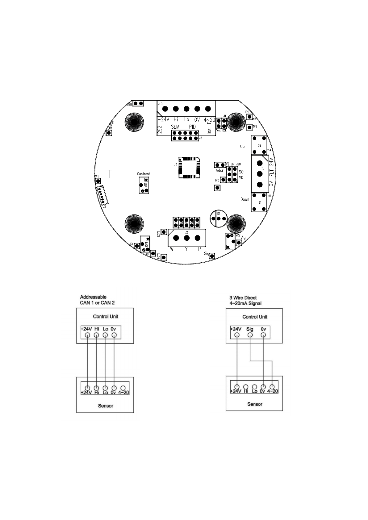
Note: Fit the end of line (EOL) link J1 if the sensor is to be installed at the end of the sensor cable.
15. If a display board is fitted via connector J5 and U12 adjust VR1 for LCD contrast.
16. Remove J9 test link for normal operation.
17. Ensure J29 address link is removed (this is only used when changing address from a panel)
Manual calibration (without PC or LCD)
18. Zero - with no gas applied, measure between Ag and Sig (Y) and adjust VR2 to give 50mv.
With J9 test link inserted, check the 4-20mA output to be 4mA as measured at TP8 to TP9 = 4mV
19. Span - apply test gas (typical 50% of range) and use UP and DOWN buttons on the PCB to give correct
4-20mA output. (50% gas = 12mA).
20. Remove gas and ensure the output returns to the 4mA level and then remove the J9 test link
Setup using magnets - LCD
WIN versions of the sensor have an LCD display which shows the Gas and range together with the sensor
address and a display of the number of seconds until an autozero will occur.
Also incorporated are 3 reed switches which can be activated using external magnets through the glass window
of the flameproof XDIwin enclosure. These magnets do not act instantly and have to be in close proximity to L, M
and R on the front display for a few seconds to activate a software setup function.
The right magnet allows the CAN address of the sensor to be changed. When the address menu is displayed with
a prompt to remove the magnet, and then the display shows the address and that the right magnet will decreases
it whilst the left magnet will increase it.
This is then stored in internal non-volatile memory and the display will automatically revert to normal operation.
The centre magnet is used to inhibit the sensor. As with the left and right magnet functions the display requests that
you remove the magnet and then the state of inhibit appears on the LCD.
The left magnet then puts the sensor into inhibit whilst the right magnet removes it. The amber LED on the front
panel under the LCD flashes when the sensor is inhibited. When all magnets are removed, the display will revert
to normal operation. The direction of the alarms is displayed as ^ for rising and v for falling but these can be
changed using left and right magnets together.
The left and right magnets together allow the calibration menu to be used. Removing both magnets as instructed
on the LCD presents the first part of this multi menu which is ZERO. With no gas present the display shows the
PPM value but also typically [0.02] This number between the square brackets shows how close the autozero has
achieved. [0.00] is definite zero and the PCB led D1 will be flickering orange.
A 15 second timer is displayed and is reset back each time a magnet is near. Waiting till timeout is acceptable but
this timeout can be speeded up by placing a magnet near to the centre position.
SPAN is the next part of the menu and gas should be applied to the sensor at this time (recommended - 100ppm
Isobutylene - see GDS application notes C645). A 2 minute counter is displayed before the next part of menu is
activated. The left magnet now increases the PPM reading and the right magnet reduces.

The actual sensor value can be seen on the display rising or falling respectively. The magnets are the equivalent of
the PCB UP and DOWN push buttons.
LOW ALARM is the next menu and left and right magnets increase and decrease this value.
HIGH ALARM is next followed by OVER RANGE alarm.
The direction of the alarms is displayed as ^ for rising and v for falling but these can be changed using left and
right magnets together.
Appendix 1
Hyperterminal Display OHLDFI
• OHand Lrepresent the Over Range, High and Low alarms respectively ^^v shows the direction of alarms
• Dindicates if a duplicate address is detected
• Findicates a fault
• Iindicates alarms inhibited
Pressing (R) when in normal runtime display causes a sensor reset to occur. Gas type with address and serial
number are then output to the PC together with alarms and calibration date, etc.
This also starts 1 minute autozero, which is useful when adjusting VR2 zero potentiometer.
Pressing (C) on the PC will list the available commands
(V) Allows a view of the gas log taken at one minute intervals over 48 hours
(A) To set the sensor address
(G) Select gas type Select the gas type from a list
(Z) Prompts to use the zero potentiometer
(S) Prompts to use the PCB buttons
($) Initialise the sensor
(%) Clear the log of sensor readings, (this takes a minute to perform)
(U) Alarm directions, Rising or falling
(D) Enter calibration date
(R) Enter the range of the gas x 10
(F) Set 4mA level Use H and L and space
(T) Set 20mA level Use H and L and space
(O) (H) (L) Set over, high and low alarm levels x 10
(M) Set the value of full range raw processor measurement value when maximum gas was applied
(E) Allows the editing of the 8 character user gas description
(X) Exit to normal display

Figure 1
Figure 2 Figure 3
Appendix 2
The PID sensor can react to gas flow and humidity. When gas is removed from the sensor, the displayed
PPM gas value may rise and take some time to return to normal. Autozero is therefore delayed by 2 minutes after
the reading has fallen below 5% of range.

MAINTENANCE, CLEANING AND CALIBRATION OF PIDS
The cell manufacturer’s application note explains when and how to maintain, clean and calibrate your PID.
The electronics in the PID-A1 and PID-AH sensor, designed to be maintenance-free, are not accessible.
Periodic sensor maintenance is required for the electrode stack and lamp.
How often does the PID require maintenance?
This depends on the environment you are measuring: if you are measuring indoor air quality with the PID-AH, where
the VOC concentrations are low and there are few particulates, a monthly or even less frequent calibration may be
adequate. However, if you are measuring high VOC concentrations with the PID-A1 and particulates are present in high
concentrations, check calibration frequently and when the PID has lost sensitivity, change the stack as explained below.
You can tell when the PID needs maintenance:
•If the baseline is climbing after you zero the PID – replace electrode stack
•If the PID becomes sensitive to humidity – replace electrode stack
•If the baseline is unstable or shifts when you move the PID – replace electrode stack
•If sensitivity has dropped too much (note the change required when checking calibration) – clean the lamp
When do I clean the PID lamp?
Cleaning of the PID lamp is recommended as the first action when presented with a PID that needs maintenance. Use the
procedure described below. It is recommended that a PID cell is recalibrated after lamp cleaning.
When do I replace the PID electrode stack?
The PID electrode stack can last the lifetime of the PID if used in clean environments, or may only last a month if used in
heavily contaminated sites. The electrode stack is a disposable item, so always hold a spare electrode stack if you are
working in a dirty environment. If the PID cell shows signs of contamination after the lamp window has been cleaned, or is
known to have been subjected to severe contamination, it should be replaced.
It is recommended that the PID is recalibrated after the stack is replaced. Instructions for replacing the electrode stack are
below.
When do I replace the PID lamp?
A PID lamp will last a long time – typically ten thousand hours and is warranted for12 months. The sensitivity of the PID is
in direct proportion to the lamp light intensity, so as a lamp ages and loses intensity, the response to a particular, low gas
concentration becomes more noisy.
Removing the electrode stack and lamp
Always use the Electrode Stack Removal Tool to remove the electrode stack; any other tools may damage your PID and
invalidate your warranty
1. Gently remove the sensor from equipment.
2. Place the PID, pellet side down, onto a clean surface.
3. Locate electrode stack removal tool into the two slots on the sides of the PID and squeeze together until electrode stack
and lamp are released.
4. Carefully lift the PID body away from the pellet and lamp.
5. Occasionally the lamp may be temporarily lodged in the cell and will need to be freed carefully with tweezers.
6. Occasionally the small spring behind the lamp will come out when the lamp is removed from the sensor. Simply replace
it into the sensor house.
Cleaning the PID Lamp
Inspection of the lamp may reveal a layer of contamination on the detection window that presents itself as a ‘blue hue.’
To check for contamination, hold the lamp in front of a light source and look across the window surface. Only clean the
lamp using our recommended lamp cleaning kit and detailed instructions. To avoid contaminating the sensor and affecting
accuracy, do not touch the lamp window with bare fingers. You may touch the body of the lamp with clean fingers.

PID lamp cleaning kit
The vial of cleaning compound contains alumina
(CAS Number 1344-28-1) as a very fine powder.
A full material safety data sheet MSDS is available on request.
Key safety issues are identified below:
Hazard identification: May cause irritation of respiratory tract and eyes
Storage: Keep container closed to prevent water adsorption and contamination
Handling:
• Do not breathe in the powder. Avoid contact with skin, eyes and clothing
• Wear suitable protective clothing
• Follow industrial hygiene practices: Wash face and hands thoroughly with soap and water after use and
before eating, drinking, smoking or applying cosmetics
• The powder carries a TVL(TWA) limit of 10 mg/m3
Use of PID lamp cleaning kit
1. Open the container of alumina polishing compound.
2. With a clean cotton bud, collect a small amount of the powder.
3. Use this cotton bud to polish the PID lamp window. Use a circular action, applying light
pressure to clean the lamp window. Do not touch the lamp window with fingers.
4. Continue polishing until an audible “squeaking” is made by the cotton bud moving over the
window surface. (usually within 15 seconds)
5. Remove the residual powder from the lamp window with a clean cotton bud. Care must be taken not to touch the tips of
cotton buds that are to be used to clean the lamps as this may contaminate them with finger oil.
6. Ensure the lamp is completely dry and remove any visible signs of contamination before refitting.
Discarding the PID electrode stack
The electrode stack does not have any toxic components, however, if it has been contaminated by toxic materials, show due
care when disposing.
Re-fitting the PID electrode stack and lamp
WARNING: Never refit a damaged lamp.
1 Place the lamp inside the O-ring seal in the pellet as illustrated. Twisting the lamp
slightly during insertion will help to ensure the lamp window is snug against the
electrode stack’s front electrode. The lamp should be freely supported by the
O-ring.
2. Continuing to hold the electrode stack between forefinger and thumb, carefully insert the lamp into recess in the sensor
ensuring that the lamp remains in position. Press the electrode stack firmly, to ensure that the electrode stack wing clips
are engaged, and the top faces of the electrode stack and sensor house are flush.
3. Refit the sensor into the sensing equipment.
4. Re-calibrate the gas detector in accordance with manufacturer’s instructions.
This document is not contractual and the equipment specification may be modified at any time without prior notice.
E: sales@gds–technologies.co.uk T: +44 (0)113 286 0166
GDS TECHNOLOGIES LTD |FUSION POINT |ASH LANE |GARFORTH |LEEDS |LS25 2GA |UK www.gds–technologies.co.uk
Table of contents
Other GDS Measuring Instrument manuals