GE Interlogix NetworX NX-2192E-EUR User manual

NX-2192E PINPOINT SYSTEM
INSTALLATION MANUAL
TABLE OF CONTENTS
1. GENERAL DESCRIPTION.......................................................................................................................... 2
2. INSTALLATION .......................................................................................................................................... 2
3. DEVICE ADDRESS CONFIGURATION...................................................................................................... 2
4. TERMINAL DESCRIPTIONS ...................................................................................................................... 2
5. WIRING DIAGRAM..................................................................................................................................... 3
6. MAXIMUM NUMBER OF DEVICES PER WIRE RUN................................................................................ 4
7. ENROLLING THE PINPOINT SYSTEM...................................................................................................... 4
8. PROGRAMMING THE MODULE................................................................................................................ 4
9. PROGRAMMING SEQUENCE EXAMPLE................................................................................................. 4
10. PROGRAMMING LOCATION GUIDE ........................................................................................................ 5
11. BATTERY CALCULATION WORKSHEET................................................................................................. 8
12. NX-2192E PROGRAMMING WORKSHEETS ............................................................................................ 9
13. APPENDIX 1 PINPOINT ADDRESS WORKSHEET............................................................................. 40
14. UL & CE NOTICES ................................................................................................................................... 44
15. SPECIFICATIONS..................................................................................................................................... 44
© 2003 GE Interlogix
All rights reserved. Printed in the USA.
NetworX
™
is a trademark of the GE Interlogix companies.
These instructions do not purport to cover all details or variations in equipment nor to provide every possible contingency to be met during
installation, operation, and maintenance. If further information is desired or if particular problems arise that are not covered sufficiently for the
purchaser’s purpose, the matter should be referred to GE Interlogix, Gladewater, Texas, USA.
This document contains proprietary informationof GE Interlogix,USA and isfurnished to itscustomer solely to assist thatcustomerin the installation,
testing, operations, and/or maintenance of the equipment described. This documentshall notbe reproduced inwhole or in partnor shall itscontents
be disclosed to any third party without the written approval of GE Interlogix. Please refer to the current GE Interlogix product catalog for detailed
warranty information.
1420 N. Main
Gladewater, TX 75647
Main
800-727-2339 Technical Support
800-727-2339
Outside the US 903-845-6941 Tech Support Fax 903-845-8409
Main Fax 903-845-6811 Sales & Literature 800-547-2556
Web: www.caddx.com www.ge-interlogix.com

NX-2192E PINPOINT SYSTEM
2
1. GENERAL DESCRIPTION
The NX-2192E is a microprocessor-controlled point ID bus interfacemodule for theNX-8Econtrol panel. ThePinPointSystem provides
two-wire bidirectional communications with up to 255individually addresseddevices. Thetotal numberof devices ina systemis limitedby
theI/O capability ofthepanel. The NX-8Ecansupportamaximumof192 zones mapped to 192input deviceaddresses andan additional
48 addresses for output devices. Warranty information is provided in the Interlogix product catalog.
2. INSTALLATION
TheNX-2192E is installedinthe NX-8E controlpanelenclosure.Threeloopoutputs are provided for interface withthe point ID devices.A
single loop output can support the full 255 point ID devices as long as the wire run limits are not exceeded. The total number of devices
can be distributed across the three loop outputs to meet wire run limit requirements.
3. DEVICE ADDRESS CONFIGURATION
Each device on the PinPoint System must be configured for a unique address with the range of 0 through 254. Address 255 is reserved.
Setting the address switches at the time that each device is installed will determine the address selection.Please refer to the worksheet
in Appendix1 on page 40.
4. TERMINAL DESCRIPTIONS
TERMINAL DESCRIPTION
PANEL- Supply Common terminal.
PANEL+ DC supply terminal for powering the NX-2192E.
COM Common terminal.
EARTH Earth Ground.
AC AC Input. Connect to a 16.5V 25, 40, or 50VA Class II UL approved transformer.
DATA
Connect to the NX8 / NX-8E control panel DATA terminal.This terminalisthe incoming data-signaling
terminalto the NX-2192E. Themaximumtotal wirerun from the controlpanel toall devicesincluding the
NX-2192E is 2500 feet.
WARNING: This terminal is not protected from damage by mis-connection. Observe caution when
connecting.
DCOUT- Connectto the NX-8/NX-8E control panelCOMMON terminal. This terminal supplies thecommon side
of the power to the NX-2192E.
DCOUT+ Not used at this time.
DCOUT- Supply Common terminal.
DCOUT+ Used only when supplied by UL approved transformer in 12V mode.
Rating: 600mA when using 12V transformer
LOOPA+ Loop A Point ID bus supply terminal.
LOOPA- Loop A Point ID bus return terminal.
LOOPB+ Loop B Point ID bus supply terminal.
LOOPB- Loop B Point ID bus return terminal.
LOOPC+ Loop C Point ID bus supply terminal.
LOOPC- Loop C Point ID bus return terminal.
For UL certified installations, the NX-2192E must be powered by the NX-8E control panel.

NX-2192E PINPOINT SYSTEM 3
5. WIRING DIAGRAM

NX-2192E PINPOINT SYSTEM
4
6. MAXIMUM NUMBER OF DEVICES PER WIRE RUN
The number of devices on an individual wire run must not exceed thenumber listed in the followingtable. If a star configuration is used,
the total wire length must not exceed 10000 feet per loop output.
Table 6-1
Length in Feet
Wire
Gauge 1000 2500 5000 7500 10000
22AWG 170 20 -- -- --
18AWG 255 170 45 5 --
16AWG 255 255 120 55 20
14AWG 255 255 240 135 80
7. ENROLLING THE PINPOINT SYSTEM
The NX-8E has the ability to automatically find and store in its memory the presence of all keypads, zone expanders, wireless receivers
and any other modules connected to the data terminal. This allows these modules to be supervised by the control panel. To enroll the
modules enter the Program Mode of the NX-8E control panel, and when the Program Mode is exited, it will automatically enroll the
devices. The enrolling process takes about 12 seconds, during which time the “Service” LED will illuminate. User codes will not be
accepted during the enrolling process. Once a module is enrolled, if it is not detected by the control, the “Service” LED will illuminate.
8. PROGRAMMING THE MODULE
To enter the program mode, press []-[8]. All of the function key LEDs will begin to flash.
Enter the "Go To Program" code (default is [9]-[7]-[1]-[3]). If the code was valid, the Service LED will flash, andthe function
LEDs will illuminate steady, indicating the device to program should be entered.
Press [4] [4] [#] for the fixed address of the PinPoint module. The Armed LED will illuminate while it is waiting for a
programming location to be entered.
Enter the desired programming location. The Armed LED will begin to flash while a programming location is being entered.
Press [#]. If this is a valid location, the Armed LED will extinguish, the Ready LED will illuminate, and the binary data for the
first segment of this location will be shown on the zone LEDS.
To change the data, enter the data followed by []. The data will be entered, andthe location will automatically increment to
thenext segment. The datafor that segment willbedisplayed. This procedure isrepeated until the lastsegment is reached.
Pressingthe [#] keywillexitfrom this location. Toreviewthe data, repeat theabove procedure, pressing the[]key without
entering data first. Each time the [] key is pressed the next segment is displayed.
Programming data is always one of two types of data. The first type is numerical, and can take on values from 0-255 or 0-15 depending
on the segment size. The second type is a feature selection type. Feature selection data is used to turn features on or off. LCD
Keypad Users Note: All steps requiredfor programmingare thesame asthe aforementionedLED keypad. TheLCD keypaddisplay will
prompt you for the data required. While in the programming mode, and not in a location, the number in parenthesis is the location you
were previously changing. For example, if the display reads "Enter location, then # (5)", it is reminding you that location 5 was the last
location you programmed. In feature selection data, the numbers of the enabled features will be displayed. However, the features not
enabled will display a hyphen (-). IMPORTANT NOTES
To program additional points after the Program Mode is exited:
1. Re-Enter the Program Mode using the instructions in Section 8, page 4 of this manual.
2. Enter Location 0 and press [1] to initialize the “Progam Mode Designation”
3. Program the desired location(s).
9. PROGRAMMING SEQUENCE EXAMPLE
The following example assumes the installation of a single input module on the bus as address number 5, with its input mapped to zone
number 9:
Enter system program mode on the NX-2192E as previously described.
Select the configuration location for zone number 9 by entering [9] [#].
Inputfor segment 1isrequested. Select thedeviceaddressof5(binary)byentering[2]-[4]-[5]-[6]-[7]-[8]so that the sequence
of (1_3_____) is displayed.
Press [] [#] to exit this location.
Select the PinPoint program mode location by entering [0] [#].
Input for segment 1 is requested. Enable PinPoint program mode by entering [1] [].
Wait for the keypad to sound a ding-dong. Press [EXIT] [EXIT] to exit the system program mode.
Refer to Location 0description fortroubleshooting ifthe keypaddoes not ding-dongafter PinPointprogram modeis complete.

NX-2192E PINPOINT SYSTEM 5
10. PROGRAMMING LOCATION GUIDE
LOCATION 0 POINT ID PROGRAM MODE
DESIGNATION 16 segments of numerical data
Location 0 is used to communicate to the PID bus interface to enter PID Program Mode.
Segment 1 must be set to [1] to “learn” points. While in this mode, all nodes able to communicate will be enabled and mapped to pre-
programmedzones. Withthisin mind, prior to entering PIDprogram mode,all zones mustbe eitherprogrammed witha serial number(for
devices without a dip switch) or a physical address (for devices with a dip switch). If programming is a success and no errors were
reported,a “0” willautomatically bewritteninto segment 1ofthis location andthekeypad will sound ading-dong.Otherwise,thenumber
oferrors will bewrittenand the keypadwillsound a triplebeep,indicatingthat errors werefound.If errors werefound, segments2-16 will
containthe locations ofthefirst 15 zoneswitherrors. Zonelocations may thenbeexaminedto determine thetypeof error thatoccurred.
NOTE:If the 8 on-boardzones are enabled, thenzones 1-8 are alreadyused andmay nothave aPID address mappedto them.
If zone doubling is enabled, then zones 1-16 are already used and may not have a PID address mapped to them.
Segments 2-16 are “read only”.
LOCATIONS 1 – 192 PROGRAMMING NODE INFORMATION
ZONES 1 - 192 3 segments of binary data
Segment 1 isused to storethephysical address ofthe corresponding node.Factorydefault is 255. Whether ornot thedevice has adip
switch, this location is programmed by the installer prior to entering PID Program Mode.
Segment 2 is used to store the input number for multiple input/output devices. Factory default is 1.
Segment 3 isused to displayanerror code ifan error(s) occurred duringthe last PID programmodecycle. The followingtableprovides
a description of the types of errors that may occur:
Table 10-1
ERROR CODE DESCRIPTION ERROR CODE DESCRIPTION
1 Node is missing. 5 Auto enroll error.
2 Multiple node responded. 6 Reserved.
3 Communication error. 7 Reserved.
4 Device type mismatch. 8 Zone programmed but node not enabled.
LOCATION 193 DEVICE OPTIONS 1 segment of feature selection data
Segment 1 selects the following options:
1 = Reserved.
2 = "On" if Loop A should be enabled; “Off” if disabled.
3 = "On" if Loop B should be enabled; “Off” if disabled.
4 = "On" if Loop C should be enabled; “Off” if disabled.
5 = “On”if 24V mode should be enabled; “Off” if 12V mode.
6 = “On” if the NX-2192Eis powered from AUX+ terminalsof the controlpanel.Turning this option“On”disablesNX-2192Epower
monitoring.
7 = “On” if any AC Fail condition should be communicated to the central monitoring station. Option 6 overrides this condition
occurring on the NX-2192E, but not individual nodes.
8 = “On” if any Low Battery condition should be communicated to the central monitoring station. Option 6 overrides this condition
occurring on the NX-2192E, but not individual nodes.
LOCATIONS 194 - 241 NODE INFORMATION FOR
OUTPUTS 1 –48 3 segments of binary data
Segment 1 isused to storethephysical address ofthe corresponding node.Whetheror not thedevicehas a dip switch,thislocationis
programmed by the installer prior to entering PID Program Mode. This segment can also be used as an indicator that the corresponding
node had an error during the last PID Program Mode cycle, because any error causes this segment to be defaulted to address 255.
Segment 2 is used to store the output number for multiple input/output devices. Default is 1.
Segment 3 isused to displayanerror code ifan error or errorsoccurred during the lastPIDProgram Mode cycle.Inthe following Table
2.1, a description of the types of errors that may occur and the bit in the error code associated with the error is outlined.

NX-2192E PINPOINT SYSTEM
6
Table 10-2
ERROR CODE DESCRIPTION
1 Node is missing.
2 Multiple node responded.
3 Communication error.
4 Device type mismatch.
5 Auto enroll error.
6 Reserved.
7 Output programmed to non-output device.
8 Output programmed but node not enabled.
LOCATION 242 – 336 (EVEN LOC) EVENT & TIME FOR
OUTPUTS 1 - 48 2 segments of numerical data
Segment 1 is used to select the particular event that will trigger the output. Refer to Table 10-3 for the specific events that can be
selected.
Segment 2 isused to selecttheamount of timeanoutput will remain activatedwhenan output triggers. Ifthislocationis programmedas
a zero, the output will follow the particular event.
Table 10-3
# Event # Event # Event
0 Always On 11 Smoke Power Reset 22 Disarmed
1
AC Fail (control or exp.) does not
follow AC Fail delay time 12 Yelping Siren 23 Ready to Arm
2 Low Battery (control or exp.) 13 Steady Siren 24 Not Ready to Arm
3 Dynamic Battery Test Time 14 Any Siren 25 Fire
4 Listen In 15 Steady Siren (temporal) 26 Fire Trouble
5 Line Seizure 16 Any Siren (temporal) 27 Chime
6 Telephone Line Fault 17 Alarm Memory 28 Beeping Keypad
7 Program Mode 18 Entry 29♦Aux 1 Keypad Function
8 Over-current (control or exp.) 19 Exit 30♦Aux 2 Keypad Function
9 Box Tamper (control or exp.) 20 Entry or Exit 31♦Panic Keypad Function
10 Siren Tamper (control or exp.) 21 Armed 32♦Code Entry (set in locs 338 - 481)
♦If set to follow condition, these events will be one second.
LOCATION 243 – 337 (ODD LOC) SPECIAL FEATURES FOR
OUTPUTS 1 - 48 2 segments of feature selection data
Segment 1 selects the following special conditions:
1 = "On" if output should time in minutes; "Off" if output times in seconds.
2 = "On" if output should latch until a code is entered; “Off” for timed.
3 = "On" if output should stop time when a code is entered.
4 = “On” for inverted output.
5 = “On” disables output during listen-in (only events 12-16).
6 = Reserved.
7 = Reserved.
8 = Reserved.
Segment 2 selects the following partitions:
1 = "On" if the event should activate when it occurs in Partition 1.
2 = "On" if the event should activate when it occurs in Partition 2.
3 = "On" if the event should activate when it occurs in Partition 3.
4 = "On" if the event should activate when it occurs in Partition 4.
5 = "On" if the event should activate when it occurs in Partition 5.
6 = "On" if the event should activate when it occurs in Partition 6.
7 = "On" if the event should activate when it occurs in Partition 7.
8 = "On" if the event should activate when it occurs in Partition 8.

NX-2192E PINPOINT SYSTEM 7
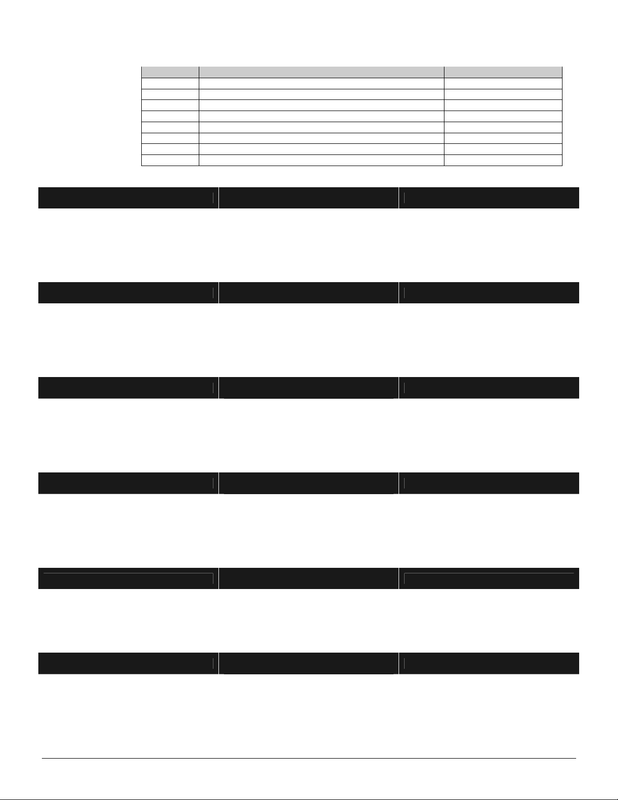
Table 10-4
LED DESCRIPTION OUTPUTS
1 "On" if code will activate output; "Off" if it will not. 1, 9, 17, 25, 33, 41
2 "On" if code will activate output; "Off" if it will not. 2, 10, 18, 26, 34, 42
3 "On" if code will activate output; "Off" if it will not. 3, 11, 19, 27, 35, 43
4 "On" if code will activate output; "Off" if it will not. 4, 12, 20, 28, 36, 44
5 "On" if code will activate output; "Off" if it will not. 5, 13, 21, 29, 37, 45
6 "On" if code will activate output; "Off" if it will not. 6, 14, 22, 30, 38, 46
7 "On" if code will activate output; "Off" if it will not. 7, 15, 23, 31, 39, 47
TABLE 10-4
IS USED TO
PROGRAM
LOCATIONS
338 - 481
8 "On" if code will activate output; "Off" if it will not. 8, 16, 24, 32, 40, 48
LOCATIONS 338 - 361 CODES 1 – 240
OUTPUTS 1 – 8 ENABLE 10 segments of feature selection data
When activating outputs with a user code (event #32), locations 338 - 361 can be used to restrict certain codes from activating certain
outputs.Each location contains10segments. Location 338 /segment1 corresponds touser1;segment10 corresponds to user 10;and
finally location 361 / segment 1 corresponds to user 231; Segment 10 corresponds to user 240. The LEDs correspond to outputs 1 - 8.
Refer to Table 10-4 for descriptions.
LOCATIONS 362 - 385 CODES 1 – 240
OUTPUTS 9 - 16 ENABLE 10 segments of feature selection data
When activating outputs with a user code (event #32), locations 362 - 385 can be used to restrict certain codes from activating certain
outputs.Each location contains10segments. Location 362 /segment1 corresponds touser1;segment10 corresponds to user 10;and
finallylocation 385 /segment1 corresponds touser231; Segment 10 correspondsto user 240. The LEDs correspond to outputs 9 - 16.
Refer to Table 10-4 for descriptions.
LOCATIONS 386 - 409 CODES 1 – 240
OUTPUTS 17 - 24 ENABLE 10 segments of feature selection data
When activating outputs with a user code (event #32), locations 386 - 409 can be used to restrict certain codes from activating certain
outputs.Each location contains10segments. Location 386 /segment1 corresponds touser1;segment10 corresponds to user 10;and
finally location 409 / segment 1 corresponds to user 231; Segment 10 corresponds to user 240. The LEDs correspond to outputs 17 -
24. Refer to Table 10-4 for descriptions.
LOCATIONS 410 - 433 CODES 1 – 240
OUTPUTS 25 - 32 ENABLE 10 segments of feature selection data
When activating outputs with a user code (event #32), locations 410 - 433 can be used to restrict certain codes from activating certain
outputs.Each location contains10segments. Location 410 /segment1 corresponds touser1;segment10 corresponds to user 10;and
finally location 433 / segment 1 corresponds to user 231; Segment 10 corresponds to user 240. The LEDs correspond to outputs 25 -
32. Refer to Table 10-4 for descriptions.
LOCATIONS 434 - 457 CODES 1 – 240
OUTPUTS 33 - 40 ENABLE 10 segments of feature selection data
When activating outputs with a user code (event #32), locations 434 - 457 can be used to restrict certain codes from activating certain
outputs.Each location contains10segments. Location 434 /segment1 corresponds touser1;segment10 corresponds to user 10;and
finally location 457 / segment 1 corresponds to user 231; Segment 10 corresponds to user 240. The LEDs correspond to outputs 33 -
40. Refer to Table 10-4 for descriptions.
LOCATIONS 458 - 481 CODES 1 – 240
OUTPUTS 41 - 48 ENABLE 10 segments of feature selection data
When activating outputs with a user code (event #32), locations 458 - 481 can be used to restrict certain codes from activating certain
outputs.Each location contains10segments. Location 458 /segment1 corresponds touser1;segment10 corresponds to user 10;and
finally location 481 / segment 1 corresponds to user 231; Segment 10 corresponds to user 240. The LEDs correspond to outputs 41 -
48. Refer to Table 10-4 for descriptions.

NX-2192E PINPOINT SYSTEM
8
11. BATTERY CALCULATION WORKSHEET
TOTAL STANDBY CURRENT
System Component Qty Standby Current TOTAL STANDBY CURRENT
NX-8E-CF 1
X 60mA = 60mA
NX-870E 1
X 20mA = 20mA
NX-148E
X 75mA =
NX-208E Aux+ X 13mA =
NX-216E
X 30mA =
NX-320E
X 10mA =
NX-507E
X 10mA =
NX-1700E
X 40mA =
NX-2192E
X 170mA =
TOTAL =
TOTAL ALARM CURRENT
System Component Qty Device Alarm Current TOTAL ALARM CURRENT
NX-8E-CF 1
X 210mA = 210mA
NX-870E 1
X 110mA = 110mA
NX-148E
X 110mA =
NX-208E Aux+ X 13mA =
NX-216E
X 60mA =
NX-320E
X 10mA =
NX-507E
X 310mA =
NX-1700E
X 110mA =
NX-2192E
X 170mA =
TOTAL =
STANDBY AMP HOURS
mA .001 Amp/mA Hrs Ah
Total Standby Current
(Step 1) X Conversion
Factor X Required Hours in
Standby =
Standby Amp Hours
ALARM HOURS
mA .001 Amp/mA Mins .0167 Hr/Min Ah
Total Alarm
Current (Step 2) X Conversion
Factor X Required Minutes in
Standby X Conversion
Factor =
Alarm Hours
MINIMUM BATTERY POWER REQUIRED
mA Ah
Standby Amp
hours (Step 3) + Alarm Amp Hours
(Step 4) =
Minimum Battery Power
Required
TOTAL STANDBY BATTERY POWER
1.15
Minimum Battery
Power (Step 5) + Battery Derating
Factor =
Total Standby Battery
Power

NX-2192E PINPOINT SYSTEM 9
12. NX-2192E Programming Worksheets
(Defaults are printed in bold italics text.)
LOC PAGE
DESCRIPTION
0 5 PROGRAM MODE DESIGNATION (Segement 1 must be set to [1] in order to ‘learn’ points)
PROGRAMMING NODE INFORMATION FOR ZONES 1 - 192
LOC PAGE Segment #1
Physical address Segment #2
Input number Segment #3
Error code Notes
1
5 1 2 3 4 5 6 7 8 1 _ _ _ _ _ _ _ _
2
5 1 2 3 4 5 6 7 8 1 _ _ _ _ _ _ _ _
3
5 1 2 3 4 5 6 7 8 1 _ _ _ _ _ _ _ _
4
5 1 2 3 4 5 6 7 8 1 _ _ _ _ _ _ _ _
5
5 1 2 3 4 5 6 7 8 1 _ _ _ _ _ _ _ _
6
5 1 2 3 4 5 6 7 8 1 _ _ _ _ _ _ _ _
7
5 1 2 3 4 5 6 7 8 1 _ _ _ _ _ _ _ _
8
5 1 2 3 4 5 6 7 8 1 _ _ _ _ _ _ _ _
9
5 1 2 3 4 5 6 7 8 1 _ _ _ _ _ _ _ _
10
5 1 2 3 4 5 6 7 8 1 _ _ _ _ _ _ _ _
11
5 1 2 3 4 5 6 7 8 1 _ _ _ _ _ _ _ _
12
5 1 2 3 4 5 6 7 8 1 _ _ _ _ _ _ _ _
13
5 1 2 3 4 5 6 7 8 1 _ _ _ _ _ _ _ _
14
5 1 2 3 4 5 6 7 8 1 _ _ _ _ _ _ _ _
15
5 1 2 3 4 5 6 7 8 1 _ _ _ _ _ _ _ _
16
5 1 2 3 4 5 6 7 8 1 _ _ _ _ _ _ _ _
17
5 1 2 3 4 5 6 7 8 1 _ _ _ _ _ _ _ _
18
5 1 2 3 4 5 6 7 8 1 _ _ _ _ _ _ _ _
19
5 1 2 3 4 5 6 7 8 1 _ _ _ _ _ _ _ _
20
5 1 2 3 4 5 6 7 8 1 _ _ _ _ _ _ _ _
21
5 1 2 3 4 5 6 7 8 1 _ _ _ _ _ _ _ _
22
5 1 2 3 4 5 6 7 8 1 _ _ _ _ _ _ _ _
23
5 1 2 3 4 5 6 7 8 1 _ _ _ _ _ _ _ _
24
5 1 2 3 4 5 6 7 8 1 _ _ _ _ _ _ _ _
25
5 1 2 3 4 5 6 7 8 1 _ _ _ _ _ _ _ _
26
5 1 2 3 4 5 6 7 8 1 _ _ _ _ _ _ _ _
27
5 1 2 3 4 5 6 7 8 1 _ _ _ _ _ _ _ _
28
5 1 2 3 4 5 6 7 8 1 _ _ _ _ _ _ _ _
29
5 1 2 3 4 5 6 7 8 1 _ _ _ _ _ _ _ _
30
5 1 2 3 4 5 6 7 8 1 _ _ _ _ _ _ _ _
31
5 1 2 3 4 5 6 7 8 1 _ _ _ _ _ _ _ _
32
5 1 2 3 4 5 6 7 8 1 _ _ _ _ _ _ _ _
33
5 1 2 3 4 5 6 7 8 1 _ _ _ _ _ _ _ _
34
5 1 2 3 4 5 6 7 8 1 _ _ _ _ _ _ _ _
35
5 1 2 3 4 5 6 7 8 1 _ _ _ _ _ _ _ _
36
5 1 2 3 4 5 6 7 8 1 _ _ _ _ _ _ _ _
37
5 1 2 3 4 5 6 7 8 1 _ _ _ _ _ _ _ _
38
5 1 2 3 4 5 6 7 8 1 _ _ _ _ _ _ _ _
39
5 1 2 3 4 5 6 7 8 1 _ _ _ _ _ _ _ _
40
5 1 2 3 4 5 6 7 8 1 _ _ _ _ _ _ _ _
41
5 1 2 3 4 5 6 7 8 1 _ _ _ _ _ _ _ _
42
5 1 2 3 4 5 6 7 8 1 _ _ _ _ _ _ _ _
43
5 1 2 3 4 5 6 7 8 1 _ _ _ _ _ _ _ _
44
5 1 2 3 4 5 6 7 8 1 _ _ _ _ _ _ _ _
45
5 1 2 3 4 5 6 7 8 1 _ _ _ _ _ _ _ _
46
5 1 2 3 4 5 6 7 8 1 _ _ _ _ _ _ _ _
47
5 1 2 3 4 5 6 7 8 1 _ _ _ _ _ _ _ _

NX-2192E PINPOINT SYSTEM
10
PROGRAMMING NODE INFORMATION FOR ZONES 1 - 192
LOC PAGE Segment #1
Physical address Segment #2
Input number Segment #3
Error code Notes
48
5 1 2 3 4 5 6 7 8 1 _ _ _ _ _ _ _ _
49
5 1 2 3 4 5 6 7 8 1 _ _ _ _ _ _ _ _
50
5 1 2 3 4 5 6 7 8 1 _ _ _ _ _ _ _ _
51
5 1 2 3 4 5 6 7 8 1 _ _ _ _ _ _ _ _
52
5 1 2 3 4 5 6 7 8 1 _ _ _ _ _ _ _ _
53
5 1 2 3 4 5 6 7 8 1 _ _ _ _ _ _ _ _
54
5 1 2 3 4 5 6 7 8 1 _ _ _ _ _ _ _ _
55
5 1 2 3 4 5 6 7 8 1 _ _ _ _ _ _ _ _
56
5 1 2 3 4 5 6 7 8 1 _ _ _ _ _ _ _ _
57
5 1 2 3 4 5 6 7 8 1 _ _ _ _ _ _ _ _
58
5 1 2 3 4 5 6 7 8 1 _ _ _ _ _ _ _ _
59
5 1 2 3 4 5 6 7 8 1 _ _ _ _ _ _ _ _
60
5 1 2 3 4 5 6 7 8 1 _ _ _ _ _ _ _ _
61
5 1 2 3 4 5 6 7 8 1 _ _ _ _ _ _ _ _
62
5 1 2 3 4 5 6 7 8 1 _ _ _ _ _ _ _ _
63
5 1 2 3 4 5 6 7 8 1 _ _ _ _ _ _ _ _
64
5 1 2 3 4 5 6 7 8 1 _ _ _ _ _ _ _ _
65
5 1 2 3 4 5 6 7 8 1 _ _ _ _ _ _ _ _
66
5 1 2 3 4 5 6 7 8 1 _ _ _ _ _ _ _ _
67
5 1 2 3 4 5 6 7 8 1 _ _ _ _ _ _ _ _
68
5 1 2 3 4 5 6 7 8 1 _ _ _ _ _ _ _ _
69
5 1 2 3 4 5 6 7 8 1 _ _ _ _ _ _ _ _
70
5 1 2 3 4 5 6 7 8 1 _ _ _ _ _ _ _ _
71
5 1 2 3 4 5 6 7 8 1 _ _ _ _ _ _ _ _
72
5 1 2 3 4 5 6 7 8 1 _ _ _ _ _ _ _ _
73
5 1 2 3 4 5 6 7 8 1 _ _ _ _ _ _ _ _
74
5 1 2 3 4 5 6 7 8 1 _ _ _ _ _ _ _ _
75
5 1 2 3 4 5 6 7 8 1 _ _ _ _ _ _ _ _
76
5 1 2 3 4 5 6 7 8 1 _ _ _ _ _ _ _ _
77
5 1 2 3 4 5 6 7 8 1 _ _ _ _ _ _ _ _
78
5 1 2 3 4 5 6 7 8 1 _ _ _ _ _ _ _ _
79
5 1 2 3 4 5 6 7 8 1 _ _ _ _ _ _ _ _
80
5 1 2 3 4 5 6 7 8 1 _ _ _ _ _ _ _ _
81
5 1 2 3 4 5 6 7 8 1 _ _ _ _ _ _ _ _
82
5 1 2 3 4 5 6 7 8 1 _ _ _ _ _ _ _ _
83
5 1 2 3 4 5 6 7 8 1 _ _ _ _ _ _ _ _
84
5 1 2 3 4 5 6 7 8 1 _ _ _ _ _ _ _ _
85
5 1 2 3 4 5 6 7 8 1 _ _ _ _ _ _ _ _
86
5 1 2 3 4 5 6 7 8 1 _ _ _ _ _ _ _ _
87
5 1 2 3 4 5 6 7 8 1 _ _ _ _ _ _ _ _
88
5 1 2 3 4 5 6 7 8 1 _ _ _ _ _ _ _ _
89
5 1 2 3 4 5 6 7 8 1 _ _ _ _ _ _ _ _
90
5 1 2 3 4 5 6 7 8 1 _ _ _ _ _ _ _ _
91
5 1 2 3 4 5 6 7 8 1 _ _ _ _ _ _ _ _
92
5 1 2 3 4 5 6 7 8 1 _ _ _ _ _ _ _ _
93
5 1 2 3 4 5 6 7 8 1 _ _ _ _ _ _ _ _
94
5 1 2 3 4 5 6 7 8 1 _ _ _ _ _ _ _ _
95
5 1 2 3 4 5 6 7 8 1 _ _ _ _ _ _ _ _
96
5 1 2 3 4 5 6 7 8 1 _ _ _ _ _ _ _ _
97
5 1 2 3 4 5 6 7 8 1 _ _ _ _ _ _ _ _
98
5 1 2 3 4 5 6 7 8 1 _ _ _ _ _ _ _ _
99
5 1 2 3 4 5 6 7 8 1 _ _ _ _ _ _ _ _
100
5 1 2 3 4 5 6 7 8 1 _ _ _ _ _ _ _ _

NX-2192E PINPOINT SYSTEM 11
PROGRAMMING NODE INFORMATION FOR ZONES 1 - 192
LOC PAGE Segment #1
Physical address Segment #2
Input number Segment #3
Error code Notes
101
5 1 2 3 4 5 6 7 8 1 _ _ _ _ _ _ _ _
102
5 1 2 3 4 5 6 7 8 1 _ _ _ _ _ _ _ _
103
5 1 2 3 4 5 6 7 8 1 _ _ _ _ _ _ _ _
104
5 1 2 3 4 5 6 7 8 1 _ _ _ _ _ _ _ _
105
5 1 2 3 4 5 6 7 8 1 _ _ _ _ _ _ _ _
106
5 1 2 3 4 5 6 7 8 1 _ _ _ _ _ _ _ _
107
5 1 2 3 4 5 6 7 8 1 _ _ _ _ _ _ _ _
108
5 1 2 3 4 5 6 7 8 1 _ _ _ _ _ _ _ _
109
5 1 2 3 4 5 6 7 8 1 _ _ _ _ _ _ _ _
110
5 1 2 3 4 5 6 7 8 1 _ _ _ _ _ _ _ _
111
5 1 2 3 4 5 6 7 8 1 _ _ _ _ _ _ _ _
112
5 1 2 3 4 5 6 7 8 1 _ _ _ _ _ _ _ _
113
5 1 2 3 4 5 6 7 8 1 _ _ _ _ _ _ _ _
114
5 1 2 3 4 5 6 7 8 1 _ _ _ _ _ _ _ _
115
5 1 2 3 4 5 6 7 8 1 _ _ _ _ _ _ _ _
116
5 1 2 3 4 5 6 7 8 1 _ _ _ _ _ _ _ _
117
5 1 2 3 4 5 6 7 8 1 _ _ _ _ _ _ _ _
118
5 1 2 3 4 5 6 7 8 1 _ _ _ _ _ _ _ _
119
5 1 2 3 4 5 6 7 8 1 _ _ _ _ _ _ _ _
120
5 1 2 3 4 5 6 7 8 1 _ _ _ _ _ _ _ _
121
5 1 2 3 4 5 6 7 8 1 _ _ _ _ _ _ _ _
122
5 1 2 3 4 5 6 7 8 1 _ _ _ _ _ _ _ _
123
5 1 2 3 4 5 6 7 8 1 _ _ _ _ _ _ _ _
124
5 1 2 3 4 5 6 7 8 1 _ _ _ _ _ _ _ _
125
5 1 2 3 4 5 6 7 8 1 _ _ _ _ _ _ _ _
126
5 1 2 3 4 5 6 7 8 1 _ _ _ _ _ _ _ _
127
5 1 2 3 4 5 6 7 8 1 _ _ _ _ _ _ _ _
128
5 1 2 3 4 5 6 7 8 1 _ _ _ _ _ _ _ _
129
5 1 2 3 4 5 6 7 8 1 _ _ _ _ _ _ _ _
130
5 1 2 3 4 5 6 7 8 1 _ _ _ _ _ _ _ _
131
5 1 2 3 4 5 6 7 8 1 _ _ _ _ _ _ _ _
132
5 1 2 3 4 5 6 7 8 1 _ _ _ _ _ _ _ _
133
5 1 2 3 4 5 6 7 8 1 _ _ _ _ _ _ _ _
134
5 1 2 3 4 5 6 7 8 1 _ _ _ _ _ _ _ _
135
5 1 2 3 4 5 6 7 8 1 _ _ _ _ _ _ _ _
136
5 1 2 3 4 5 6 7 8 1 _ _ _ _ _ _ _ _
137
5 1 2 3 4 5 6 7 8 1 _ _ _ _ _ _ _ _
138
5 1 2 3 4 5 6 7 8 1 _ _ _ _ _ _ _ _
139
5 1 2 3 4 5 6 7 8 1 _ _ _ _ _ _ _ _
140
5 1 2 3 4 5 6 7 8 1 _ _ _ _ _ _ _ _
141
5 1 2 3 4 5 6 7 8 1 _ _ _ _ _ _ _ _
142
5 1 2 3 4 5 6 7 8 1 _ _ _ _ _ _ _ _
143
5 1 2 3 4 5 6 7 8 1 _ _ _ _ _ _ _ _
144
5 1 2 3 4 5 6 7 8 1 _ _ _ _ _ _ _ _
145
5 1 2 3 4 5 6 7 8 1 _ _ _ _ _ _ _ _
146
5 1 2 3 4 5 6 7 8 1 _ _ _ _ _ _ _ _
147
5 1 2 3 4 5 6 7 8 1 _ _ _ _ _ _ _ _
148
5 1 2 3 4 5 6 7 8 1 _ _ _ _ _ _ _ _
149
5 1 2 3 4 5 6 7 8 1 _ _ _ _ _ _ _ _
150
5 1 2 3 4 5 6 7 8 1 _ _ _ _ _ _ _ _
151
5 1 2 3 4 5 6 7 8 1 _ _ _ _ _ _ _ _
152
5 1 2 3 4 5 6 7 8 1 _ _ _ _ _ _ _ _
153
5 1 2 3 4 5 6 7 8 1 _ _ _ _ _ _ _ _

NX-2192E PINPOINT SYSTEM
12
PROGRAMMING NODE INFORMATION FOR ZONES 1 - 192
LOC PAGE Segment #1
Physical address Segment #2
Input number Segment #3
Error code Notes
154
5 1 2 3 4 5 6 7 8 1 _ _ _ _ _ _ _ _
155
5 1 2 3 4 5 6 7 8 1 _ _ _ _ _ _ _ _
156
5 1 2 3 4 5 6 7 8 1 _ _ _ _ _ _ _ _
157
5 1 2 3 4 5 6 7 8 1 _ _ _ _ _ _ _ _
158
5 1 2 3 4 5 6 7 8 1 _ _ _ _ _ _ _ _
159
5 1 2 3 4 5 6 7 8 1 _ _ _ _ _ _ _ _
160
5 1 2 3 4 5 6 7 8 1 _ _ _ _ _ _ _ _
161
5 1 2 3 4 5 6 7 8 1 _ _ _ _ _ _ _ _
162
5 1 2 3 4 5 6 7 8 1 _ _ _ _ _ _ _ _
163
5 1 2 3 4 5 6 7 8 1 _ _ _ _ _ _ _ _
164
5 1 2 3 4 5 6 7 8 1 _ _ _ _ _ _ _ _
165
5 1 2 3 4 5 6 7 8 1 _ _ _ _ _ _ _ _
166
5 1 2 3 4 5 6 7 8 1 _ _ _ _ _ _ _ _
167
5 1 2 3 4 5 6 7 8 1 _ _ _ _ _ _ _ _
168
5 1 2 3 4 5 6 7 8 1 _ _ _ _ _ _ _ _
169
5 1 2 3 4 5 6 7 8 1 _ _ _ _ _ _ _ _
170
5 1 2 3 4 5 6 7 8 1 _ _ _ _ _ _ _ _
171
5 1 2 3 4 5 6 7 8 1 _ _ _ _ _ _ _ _
172
5 1 2 3 4 5 6 7 8 1 _ _ _ _ _ _ _ _
173
5 1 2 3 4 5 6 7 8 1 _ _ _ _ _ _ _ _
174
5 1 2 3 4 5 6 7 8 1 _ _ _ _ _ _ _ _
175
5 1 2 3 4 5 6 7 8 1 _ _ _ _ _ _ _ _
176
5 1 2 3 4 5 6 7 8 1 _ _ _ _ _ _ _ _
177
5 1 2 3 4 5 6 7 8 1 _ _ _ _ _ _ _ _
178
5 1 2 3 4 5 6 7 8 1 _ _ _ _ _ _ _ _
179
5 1 2 3 4 5 6 7 8 1 _ _ _ _ _ _ _ _
180
5 1 2 3 4 5 6 7 8 1 _ _ _ _ _ _ _ _
181
5 1 2 3 4 5 6 7 8 1 _ _ _ _ _ _ _ _
182
5 1 2 3 4 5 6 7 8 1 _ _ _ _ _ _ _ _
183
5 1 2 3 4 5 6 7 8 1 _ _ _ _ _ _ _ _
184
5 1 2 3 4 5 6 7 8 1 _ _ _ _ _ _ _ _
185
5 1 2 3 4 5 6 7 8 1 _ _ _ _ _ _ _ _
186
5 1 2 3 4 5 6 7 8 1 _ _ _ _ _ _ _ _
187
5 1 2 3 4 5 6 7 8 1 _ _ _ _ _ _ _ _
188
5 1 2 3 4 5 6 7 8 1 _ _ _ _ _ _ _ _
189
5 1 2 3 4 5 6 7 8 1 _ _ _ _ _ _ _ _
190
5 1 2 3 4 5 6 7 8 1 _ _ _ _ _ _ _ _
191
5 1 2 3 4 5 6 7 8 1 _ _ _ _ _ _ _ _
192
5 1 2 3 4 5 6 7 8 1 _ _ _ _ _ _ _ _

NX-2192E PINPOINT SYSTEM 13
LOC PAGE DESCRIPTION
DEVICE OPTIONS193
5 1 = Reserved.
2 = "On" if Loop A should be enabled; “Off” if disabled.
3 = "On" if Loop B should be enabled; “Off” if disabled.
4 = "On" if Loop C should be enabled; “Off” if disabled.
5 = “On” if 24V mode; “Off” if 12V mode.
6 = “On”if the NX-
2192Eis powered from AUX+ terminalsof the controlpanel.Turning this option“On”disables
NX-2192E power monitoring.
7 = “On” if any AC Fail condition should be co
mmunicated to the central monitoring station. Option 6 overrides
this condition occurring on the NX-2192E, but not individual nodes.
8 =
“On” if any Low Battery condition should be communicated to the central monitoring station. Option 6
overrides this condition occurring on the NX-2192E, but not individual nodes.
PROGRAMMING NODE INFORMATION FOR OUTPUTS 1 - 48
LOC PAGE OUTPUT
Segment #1
Physical address Segment #2
Output number Segment #3
Error code Notes
194
5 1 1 2 3 4 5 6 7 8 1 _ _ _ _ _ _ _ _
195
5 2 1 2 3 4 5 6 7 8 1 _ _ _ _ _ _ _ _
196
5 3 1 2 3 4 5 6 7 8 1 _ _ _ _ _ _ _ _
197
5 4 1 2 3 4 5 6 7 8 1 _ _ _ _ _ _ _ _
198
5 5 1 2 3 4 5 6 7 8 1 _ _ _ _ _ _ _ _
199
5 6 1 2 3 4 5 6 7 8 1 _ _ _ _ _ _ _ _
200
5 7 1 2 3 4 5 6 7 8 1 _ _ _ _ _ _ _ _
201
5 8 1 2 3 4 5 6 7 8 1 _ _ _ _ _ _ _ _
202
5 9 1 2 3 4 5 6 7 8 1 _ _ _ _ _ _ _ _
203
5 10 1 2 3 4 5 6 7 8 1 _ _ _ _ _ _ _ _
204
5 11 1 2 3 4 5 6 7 8 1 _ _ _ _ _ _ _ _
205
5 12 1 2 3 4 5 6 7 8 1 _ _ _ _ _ _ _ _
206
5 13 1 2 3 4 5 6 7 8 1 _ _ _ _ _ _ _ _
207
5 14 1 2 3 4 5 6 7 8 1 _ _ _ _ _ _ _ _
208
5 15 1 2 3 4 5 6 7 8 1 _ _ _ _ _ _ _ _
209
5 16 1 2 3 4 5 6 7 8 1 _ _ _ _ _ _ _ _
210
5 17 1 2 3 4 5 6 7 8 1 _ _ _ _ _ _ _ _
211
5 18 1 2 3 4 5 6 7 8 1 _ _ _ _ _ _ _ _
212
5 19 1 2 3 4 5 6 7 8 1 _ _ _ _ _ _ _ _
213
5 20 1 2 3 4 5 6 7 8 1 _ _ _ _ _ _ _ _
214
5 21 1 2 3 4 5 6 7 8 1 _ _ _ _ _ _ _ _
215
5 22 1 2 3 4 5 6 7 8 1 _ _ _ _ _ _ _ _
216
5 23 1 2 3 4 5 6 7 8 1 _ _ _ _ _ _ _ _
217
5 24 1 2 3 4 5 6 7 8 1 _ _ _ _ _ _ _ _
218
5 25 1 2 3 4 5 6 7 8 1 _ _ _ _ _ _ _ _
219
5 26 1 2 3 4 5 6 7 8 1 _ _ _ _ _ _ _ _
220
5 27 1 2 3 4 5 6 7 8 1 _ _ _ _ _ _ _ _
221
5 28 1 2 3 4 5 6 7 8 1 _ _ _ _ _ _ _ _
222
5 29 1 2 3 4 5 6 7 8 1 _ _ _ _ _ _ _ _
223
5 30 1 2 3 4 5 6 7 8 1 _ _ _ _ _ _ _ _
224
5 31 1 2 3 4 5 6 7 8 1 _ _ _ _ _ _ _ _
225
5 32 1 2 3 4 5 6 7 8 1 _ _ _ _ _ _ _ _
226
5 33 1 2 3 4 5 6 7 8 1 _ _ _ _ _ _ _ _
227
5 34 1 2 3 4 5 6 7 8 1 _ _ _ _ _ _ _ _
228
5 35 1 2 3 4 5 6 7 8 1 _ _ _ _ _ _ _ _
229
5 36 1 2 3 4 5 6 7 8 1 _ _ _ _ _ _ _ _
230
5 37 1 2 3 4 5 6 7 8 1 _ _ _ _ _ _ _ _
231
5 38 1 2 3 4 5 6 7 8 1 _ _ _ _ _ _ _ _
232
5 39 1 2 3 4 5 6 7 8 1 _ _ _ _ _ _ _ _
233
5 40 1 2 3 4 5 6 7 8 1 _ _ _ _ _ _ _ _

NX-2192E PINPOINT SYSTEM
14
PROGRAMMING NODE INFORMATION FOR OUTPUTS 1 - 48
LOC PAGE OUTPUT
Segment #1
Physical address Segment #2
Output number Segment #3
Error code Notes
234
5 41 1 2 3 4 5 6 7 8 1 _ _ _ _ _ _ _ _
235
5 42 1 2 3 4 5 6 7 8 1 _ _ _ _ _ _ _ _
236
5 43 1 2 3 4 5 6 7 8 1 _ _ _ _ _ _ _ _
237
5 44 1 2 3 4 5 6 7 8 1 _ _ _ _ _ _ _ _
238
5 45 1 2 3 4 5 6 7 8 1 _ _ _ _ _ _ _ _
239
5 46 1 2 3 4 5 6 7 8 1 _ _ _ _ _ _ _ _
240
5 47 1 2 3 4 5 6 7 8 1 _ _ _ _ _ _ _ _
241
5 48 1 2 3 4 5 6 7 8 1 _ _ _ _ _ _ _ _
USE THE FOLLOWING TABLE FOR
EVEN NUMBERED LOCATIONS 242 – 336
(EVENT / TIME)
# Event # Event
0 Always On 17 Alarm Memory
1 AC Fail (control or exp.) does
not follow AC Fail delay time 18 Entry
2 Low Battery (control or exp.) 19 Exit
3 Dynamic Battery Test Time 20 Entry or Exit
4 Listen In 21 Armed
5 Line Seizure 22 Disarmed
6 Telephone Line Fault 23 Ready to Arm
7 Program Mode 24 Not Ready to Arm
8 Over-current (control or exp.) 25 Fire
9 Box Tamper (control or exp.) 26 Fire Trouble
10 Siren Tamper (control or exp.) 27 Chime
11 Smoke Power Reset 28 Beeping Keypad
12 Yelping Siren 29
♦
Aux 1 Keypad Function
13 Steady Siren 30
♦
Aux 2 Keypad Function
14 Any Siren 31
♦
Panic Keypad Function
15 Steady Siren (temporal) 32
♦
Code Entry ( locs 338 - 481)
16 Any Siren (temporal)
USE THE FOLLOWING TABLE FOR
ODD NUMBERED LOCATIONS 243 – 337
(SPECIAL FEATURES)
SEG 1 DESCRIPTION SEG 2 DESCRIPTION
1 =
ON times in minutes
OFF if times in seconds 1 =
On if event activates output in
Partition 1
2 =
ON to latch until a code is
entered; OFF for timed 2 =
On if event activates output in
Partition 2
3 =
ON if output should stop time
when a code is entered 3 =
On if event activates output in
Partition 3
4 =
ON for inverted output 4 =
On if event activates output in
Partition 4
5 =
ON disables output during
listen-in (only events 12-16) 5 =
On if event activates output in
Partition 5
6 =
Reserved 6 =
On if event activates output in
Partition 6
7 =
Reserved 7 =
On if event activates output in
Partition 7
8 =
Reserved 8 =
On if event activates output in
Partition 8
LOC PAGE DESCRIPTION SEG 1 DEFAULT
SEG 1 DATA SEG 2 DEFAULT
SEG 2 DATA
242
6 EVENT / TIME – OUTPUT 1 14=Any Siren 0=Follow Evt
243
6 FEATURES – OUTPUT 1 _ _ _ _ _ _ _ _ 1 2 3 4 5 6 7 8
244
6 EVENT / TIME – OUTPUT 2 14=Any Siren 0=Follow Evt
245
6 FEATURES – OUTPUT 2 _ _ _ _ _ _ _ _ 1 2 3 4 5 6 7 8
246
6 EVENT / TIME – OUTPUT 3 14=Any Siren 0=Follow Evt
247
6 FEATURES – OUTPUT 3 _ _ _ _ _ _ _ _ 1 2 3 4 5 6 7 8
248
6 EVENT / TIME – OUTPUT 4 14=Any Siren 0=Follow Evt
249
6 FEATURES – OUTPUT 4 _ _ _ _ _ _ _ _ 1 2 3 4 5 6 7 8
250
6 EVENT / TIME – OUTPUT 5 14=Any Siren 0=Follow Evt
251
6 FEATURES – OUTPUT 5 _ _ _ _ _ _ _ _ 1 2 3 4 5 6 7 8
252
6 EVENT / TIME – OUTPUT 6 14=Any Siren 0=Follow Evt
253
6 FEATURES – OUTPUT 6 _ _ _ _ _ _ _ _ 1 2 3 4 5 6 7 8
254
6 EVENT / TIME – OUTPUT 7 14=Any Siren 0=Follow Evt
255
6 FEATURES – OUTPUT 7 _ _ _ _ _ _ _ _ 1 2 3 4 5 6 7 8
256
6 EVENT / TIME – OUTPUT 8 14=Any Siren 0=Follow Evt
257
6 FEATURES – OUTPUT 8 _ _ _ _ _ _ _ _ 1 2 3 4 5 6 7 8
258
6 EVENT / TIME – OUTPUT 9 14=Any Siren 0=Follow Evt
259
6 FEATURES – OUTPUT 9 _ _ _ _ _ _ _ _ 1 2 3 4 5 6 7 8
260
6 EVENT / TIME – OUTPUT 10 14=Any Siren 0=Follow Evt
261
6 FEATURES – OUTPUT 10 _ _ _ _ _ _ _ _ 1 2 3 4 5 6 7 8
262
6 EVENT / TIME – OUTPUT 11 14=Any Siren 0=Follow Evt
263
6 FEATURES – OUTPUT 11 _ _ _ _ _ _ _ _ 1 2 3 4 5 6 7 8
264
6 EVENT / TIME – OUTPUT 12 14=Any Siren 0=Follow Evt
265
6 FEATURES – OUTPUT 12 _ _ _ _ _ _ _ _ 1 2 3 4 5 6 7 8
266
6 EVENT / TIME – OUTPUT 13 14=Any Siren 0=Follow Evt
267
6 FEATURES – OUTPUT 13 _ _ _ _ _ _ _ _ 1 2 3 4 5 6 7 8
268
6 EVENT / TIME – OUTPUT 14 14=Any Siren 0=Follow Evt
269
6 FEATURES – OUTPUT 14 _ _ _ _ _ _ _ _ 1 2 3 4 5 6 7 8
270
6 EVENT / TIME – OUTPUT 15 14=Any Siren 0=Follow Evt
271
6 FEATURES – OUTPUT 15 _ _ _ _ _ _ _ _ 1 2 3 4 5 6 7 8
272
6 EVENT / TIME – OUTPUT 16 14=Any Siren 0=Follow Evt
273
6 FEATURES – OUTPUT 16 _ _ _ _ _ _ _ _ 1 2 3 4 5 6 7 8

NX-2192E PINPOINT SYSTEM 15
LOC PAGE DESCRIPTION SEG 1 DEFAULT
SEG 1 DATA SEG 2 DEFAULT
SEG 2 DATA
274
6 EVENT / TIME – OUTPUT 17 14=Any Siren 0=Follow Evt
275
6 FEATURES – OUTPUT 17 _ _ _ _ _ _ _ _ 1 2 3 4 5 6 7 8
276
6 EVENT / TIME – OUTPUT 18 14=Any Siren 0=Follow Evt
277
6 FEATURES – OUTPUT 18 _ _ _ _ _ _ _ _ 1 2 3 4 5 6 7 8
278
6 EVENT / TIME – OUTPUT 19 14=Any Siren 0=Follow Evt
279
6 FEATURES – OUTPUT 19 _ _ _ _ _ _ _ _ 1 2 3 4 5 6 7 8
280
6 EVENT / TIME – OUTPUT 20 14=Any Siren 0=Follow Evt
281
6 FEATURES – OUTPUT 20 _ _ _ _ _ _ _ _ 1 2 3 4 5 6 7 8
282
6 EVENT / TIME – OUTPUT 21 14=Any Siren 0=Follow Evt
283
6 FEATURES – OUTPUT 21 _ _ _ _ _ _ _ _ 1 2 3 4 5 6 7 8
284
6 EVENT / TIME – OUTPUT 22 14=Any Siren 0=Follow Evt
285
6 FEATURES – OUTPUT 22 _ _ _ _ _ _ _ _ 1 2 3 4 5 6 7 8
286
6 EVENT /TIME – OUTPUT 23 14=Any Siren 0=Follow Evt
287
6 FEATURES – OUTPUT 23 _ _ _ _ _ _ _ _ 1 2 3 4 5 6 7 8
288
6 EVENT / TIME – OUTPUT 24 14=Any Siren 0=Follow Evt
289
6 FEATURES – OUTPUT 24 _ _ _ _ _ _ _ _ 1 2 3 4 5 6 7 8
290
6 EVENT / TIME – OUTPUT 25 14=Any Siren 0=Follow Evt
291
6 FEATURES – OUTPUT 25 _ _ _ _ _ _ _ _ 1 2 3 4 5 6 7 8
292
6 EVENT / TIME – OUTPUT 26 14=Any Siren 0=Follow Evt
293
6 FEATURES – OUTPUT 26 _ _ _ _ _ _ _ _ 1 2 3 4 5 6 7 8
294
6 EVENT / TIME – OUTPUT 27 14=Any Siren 0=Follow Evt
295
6 FEATURES – OUTPUT 27 _ _ _ _ _ _ _ _ 1 2 3 4 5 6 7 8
296
6 EVENT / TIME – OUTPUT 28 14=Any Siren 0=Follow Evt
297
6 FEATURES – OUTPUT 28 _ _ _ _ _ _ _ _ 1 2 3 4 5 6 7 8
298
6 EVENT / TIME – OUTPUT 29 14=Any Siren 0=Follow Evt
299
6 FEATURES – OUTPUT 29 _ _ _ _ _ _ _ _ 1 2 3 4 5 6 7 8
300
6 EVENT / TIME – OUTPUT 30 14=Any Siren 0=Follow Evt
301
6 FEATURES – OUTPUT 30 _ _ _ _ _ _ _ _ 1 2 3 4 5 6 7 8
302
6 EVENT / TIME – OUTPUT 31 14=Any Siren 0=Follow Evt
303
6 FEATURES – OUTPUT 31 _ _ _ _ _ _ _ _ 1 2 3 4 5 6 7 8
304
6 EVENT / TIME – OUTPUT 32 14=Any Siren 0=Follow Evt
305
6 FEATURES – OUTPUT 32 _ _ _ _ _ _ _ _ 1 2 3 4 5 6 7 8
306
6 EVENT / TIME – OUTPUT 33 14=Any Siren 0=Follow Evt
307
6 FEATURES – OUTPUT 33 _ _ _ _ _ _ _ _ 1 2 3 4 5 6 7 8
308
6 EVENT / TIME – OUTPUT 34 14=Any Siren 0=Follow Evt
309
6 FEATURES – OUTPUT 34 _ _ _ _ _ _ _ _ 1 2 3 4 5 6 7 8
310
6 EVENT / TIME – OUTPUT 35 14=Any Siren 0=Follow Evt
311
6 FEATURES – OUTPUT 35 _ _ _ _ _ _ _ _ 1 2 3 4 5 6 7 8
312
6 EVENT / TIME – OUTPUT 36 14=Any Siren 0=Follow Evt
313
6 FEATURES – OUTPUT 36 _ _ _ _ _ _ _ _ 1 2 3 4 5 6 7 8
314
6 EVENT / TIME – OUTPUT 37 14=Any Siren 0=Follow Evt
315
6 FEATURES – OUTPUT 37 _ _ _ _ _ _ _ _ 1 2 3 4 5 6 7 8
316
6 EVENT / TIME – OUTPUT 38 14=Any Siren 0=Follow Evt
317
6 FEATURES – OUTPUT 38 _ _ _ _ _ _ _ _ 1 2 3 4 5 6 7 8
318
6 EVENT / TIME – OUTPUT 39 14=Any Siren 0=Follow Evt
319
6 FEATURES – OUTPUT 39 _ _ _ _ _ _ _ _ 1 2 3 4 5 6 7 8
320
6 EVENT / TIME – OUTPUT 40 14=Any Siren 0=Follow Evt
321
6 FEATURES – OUTPUT 40 _ _ _ _ _ _ _ _ 1 2 3 4 5 6 7 8
322
6 EVENT / TIME – OUTPUT 41 14=Any Siren 0=Follow Evt
323
6 FEATURES – OUTPUT 41 _ _ _ _ _ _ _ _ 1 2 3 4 5 6 7 8
324
6 EVENT / TIME – OUTPUT 42 14=Any Siren 0=Follow Evt
325
6 FEATURES – OUTPUT 42 _ _ _ _ _ _ _ _ 1 2 3 4 5 6 7 8
326
6 EVENT / TIME – OUTPUT 43 14=Any Siren 0=Follow Evt
327
6 FEATURES – OUTPUT 43 _ _ _ _ _ _ _ _ 1 2 3 4 5 6 7 8
328
6 EVENT / TIME – OUTPUT 44 14=Any Siren 0=Follow Evt
329
6 FEATURES – OUTPUT 44 _ _ _ _ _ _ _ _ 1 2 3 4 5 6 7 8
330
6 EVENT / TIME – OUTPUT 45 14=Any Siren 0=Follow Evt
331
6 FEATURES – OUTPUT 45 _ _ _ _ _ _ _ _ 1 2 3 4 5 6 7 8
332
6 EVENT / TIME – OUTPUT 46 14=Any Siren 0=Follow Evt
333
6 FEATURES – OUTPUT 46 _ _ _ _ _ _ _ _ 1 2 3 4 5 6 7 8
334
6 EVENT / TIME – OUTPUT 47 14=Any Siren 0=Follow Evt
335
6 FEATURES – OUTPUT 47 _ _ _ _ _ _ _ _ 1 2 3 4 5 6 7 8

NX-2192E PINPOINT SYSTEM
16
LOC PAGE DESCRIPTION SEG 1 DEFAULT
SEG 1 DATA SEG 2 DEFAULT
SEG 2 DATA
336
6 EVENT / TIME – OUTPUT 48 14=Any Siren 0=Follow Evt
337
6 FEATURES – OUTPUT 48 _ _ _ _ _ _ _ _ 1 2 3 4 5 6 7 8
LOC PAGE DESCRIPTION
CODES 1-10 OUTPUT SELECTION (Circle the numbers to disable)
User 1 2 3 4 5 6 7 8 9 10
338
7
Output 1
Output 2
Output 3
Output 4
Output 5
Output 6
Output 7
Output 8
1
2
3
4
5
6
7
8
1
2
3
4
5
6
7
8
1
2
3
4
5
6
7
8
1
2
3
4
5
6
7
8
1
2
3
4
5
6
7
8
1
2
3
4
5
6
7
8
1
2
3
4
5
6
7
8
1
2
3
4
5
6
7
8
1
2
3
4
5
6
7
8
1
2
3
4
5
6
7
8
CODES 11-20 OUTPUT SELECTION (Circle the numbers to disable)
User 11 12 13 14 15 16 17 18 19 20
339
7
Output 1
Output 2
Output 3
Output 4
Output 5
Output 6
Output 7
Output 8
1
2
3
4
5
6
7
8
1
2
3
4
5
6
7
8
1
2
3
4
5
6
7
8
1
2
3
4
5
6
7
8
1
2
3
4
5
6
7
8
1
2
3
4
5
6
7
8
1
2
3
4
5
6
7
8
1
2
3
4
5
6
7
8
1
2
3
4
5
6
7
8
1
2
3
4
5
6
7
8
CODES 21-30 OUTPUT SELECTION (Circle the numbers to disable)
User 21 22 23 24 25 26 27 28 29 30
340
7
Output 1
Output 2
Output 3
Output 4
Output 5
Output 6
Output 7
Output 8
1
2
3
4
5
6
7
8
1
2
3
4
5
6
7
8
1
2
3
4
5
6
7
8
1
2
3
4
5
6
7
8
1
2
3
4
5
6
7
8
1
2
3
4
5
6
7
8
1
2
3
4
5
6
7
8
1
2
3
4
5
6
7
8
1
2
3
4
5
6
7
8
1
2
3
4
5
6
7
8
CODES 31-40 OUTPUT SELECTION (Circle the numbers to program)
User 31 32 33 34 35 36 37 38 39 40
341
7
Output 1
Output 2
Output 3
Output 4
Output 5
Output 6
Output 7
Output 8
1
2
3
4
5
6
7
8
1
2
3
4
5
6
7
8
1
2
3
4
5
6
7
8
1
2
3
4
5
6
7
8
1
2
3
4
5
6
7
8
1
2
3
4
5
6
7
8
1
2
3
4
5
6
7
8
1
2
3
4
5
6
7
8
1
2
3
4
5
6
7
8
1
2
3
4
5
6
7
8
CODES 41-50 OUTPUT SELECTION (Circle the numbers to disable)
User 41 42 43 44 45 46 47 48 49 50
342
7
Output 1
Output 2
Output 3
Output 4
Output 5
Output 6
Output 7
Output 8
1
2
3
4
5
6
7
8
1
2
3
4
5
6
7
8
1
2
3
4
5
6
7
8
1
2
3
4
5
6
7
8
1
2
3
4
5
6
7
8
1
2
3
4
5
6
7
8
1
2
3
4
5
6
7
8
1
2
3
4
5
6
7
8
1
2
3
4
5
6
7
8
1
2
3
4
5
6
7
8
CODES 51-60 OUTPUT SELECTION (Circle the numbers to disable)
User 51 52 53 54 55 56 57 58 59 60
343
7
Output 1
Output 2
Output 3
Output 4
Output 5
Output 6
Output 7
Output 8
1
2
3
4
5
6
7
8
1
2
3
4
5
6
7
8
1
2
3
4
5
6
7
8
1
2
3
4
5
6
7
8
1
2
3
4
5
6
7
8
1
2
3
4
5
6
7
8
1
2
3
4
5
6
7
8
1
2
3
4
5
6
7
8
1
2
3
4
5
6
7
8
1
2
3
4
5
6
7
8

NX-2192E PINPOINT SYSTEM 17
LOC PAGE DESCRIPTION
CODES 61-70 OUTPUT SELECTION (Circle the numbers to disable)
User 61 62 63 64 65 66 67 68 69 70
344
7
Output 1
Output 2
Output 3
Output 4
Output 5
Output 6
Output 7
Output 8
1
2
3
4
5
6
7
8
1
2
3
4
5
6
7
8
1
2
3
4
5
6
7
8
1
2
3
4
5
6
7
8
1
2
3
4
5
6
7
8
1
2
3
4
5
6
7
8
1
2
3
4
5
6
7
8
1
2
3
4
5
6
7
8
1
2
3
4
5
6
7
8
1
2
3
4
5
6
7
8
CODES 71-80 OUTPUT SELECTION (Circle the numbers to disable)
User 71 72 73 74 75 76 77 78 79 80
345
7
Output 1
Output 2
Output 3
Output 4
Output 5
Output 6
Output 7
Output 8
1
2
3
4
5
6
7
8
1
2
3
4
5
6
7
8
1
2
3
4
5
6
7
8
1
2
3
4
5
6
7
8
1
2
3
4
5
6
7
8
1
2
3
4
5
6
7
8
1
2
3
4
5
6
7
8
1
2
3
4
5
6
7
8
1
2
3
4
5
6
7
8
1
2
3
4
5
6
7
8
CODES 81-90 OUTPUT SELECTION (Circle the numbers to disable)
User 81 82 83 84 85 86 87 88 89 90
346
Output 1
Output 2
Output 3
Output 4
Output 5
Output 6
Output 7
Output 8
1
2
3
4
5
6
7
8
1
2
3
4
5
6
7
8
1
2
3
4
5
6
7
8
1
2
3
4
5
6
7
8
1
2
3
4
5
6
7
8
1
2
3
4
5
6
7
8
1
2
3
4
5
6
7
8
1
2
3
4
5
6
7
8
1
2
3
4
5
6
7
8
1
2
3
4
5
6
7
8
CODES 91-100 OUTPUT SELECTION (Circle the numbers to disable)
User 91 92 93 94 95 96 97 98 99 100
347
7
Output 1
Output 2
Output 3
Output 4
Output 5
Output 6
Output 7
Output 8
1
2
3
4
5
6
7
8
1
2
3
4
5
6
7
8
1
2
3
4
5
6
7
8
1
2
3
4
5
6
7
8
1
2
3
4
5
6
7
8
1
2
3
4
5
6
7
8
1
2
3
4
5
6
7
8
1
2
3
4
5
6
7
8
1
2
3
4
5
6
7
8
1
2
3
4
5
6
7
8
CODES 101-110 OUTPUT SELECTION (Circle the numbers to disable)
User 101 102 103 104 105 106 107 108 109 110
348
7
Output 1
Output 2
Output 3
Output 4
Output 5
Output 6
Output 7
Output 8
1
2
3
4
5
6
7
8
1
2
3
4
5
6
7
8
1
2
3
4
5
6
7
8
1
2
3
4
5
6
7
8
1
2
3
4
5
6
7
8
1
2
3
4
5
6
7
8
1
2
3
4
5
6
7
8
1
2
3
4
5
6
7
8
1
2
3
4
5
6
7
8
1
2
3
4
5
6
7
8
CODES 111-120 OUTPUT SELECTION (Circle the numbers to disable)
User 111 112 113 114 115 116 117 118 119 120
349
7
Output 1
Output 2
Output 3
Output 4
Output 5
Output 6
Output 7
Output 8
1
2
3
4
5
6
7
8
1
2
3
4
5
6
7
8
1
2
3
4
5
6
7
8
1
2
3
4
5
6
7
8
1
2
3
4
5
6
7
8
1
2
3
4
5
6
7
8
1
2
3
4
5
6
7
8
1
2
3
4
5
6
7
8
1
2
3
4
5
6
7
8
1
2
3
4
5
6
7
8

NX-2192E PINPOINT SYSTEM
18
LOC PAGE DESCRIPTION
CODES 121-130 OUTPUT SELECTION (Circle the numbers to disable)
User 121 122 123 124 125 126 127 128 129 130
350
7
Output 1
Output 2
Output 3
Output 4
Output 5
Output 6
Output 7
Output 8
1
2
3
4
5
6
7
8
1
2
3
4
5
6
7
8
1
2
3
4
5
6
7
8
1
2
3
4
5
6
7
8
1
2
3
4
5
6
7
8
1
2
3
4
5
6
7
8
1
2
3
4
5
6
7
8
1
2
3
4
5
6
7
8
1
2
3
4
5
6
7
8
1
2
3
4
5
6
7
8
CODES 131-140 OUTPUT SELECTION (Circle the numbers to disable)
User 131 132 133 134 135 136 137 138 139 140
351
7
Output 1
Output 2
Output 3
Output 4
Output 5
Output 6
Output 7
Output 8
1
2
3
4
5
6
7
8
1
2
3
4
5
6
7
8
1
2
3
4
5
6
7
8
1
2
3
4
5
6
7
8
1
2
3
4
5
6
7
8
1
2
3
4
5
6
7
8
1
2
3
4
5
6
7
8
1
2
3
4
5
6
7
8
1
2
3
4
5
6
7
8
1
2
3
4
5
6
7
8
CODES 141-150 OUTPUT SELECTION (Circle the numbers to disable)
User 141 142 143 144 145 146 147 148 149 150
352
7
Output 1
Output 2
Output 3
Output 4
Output 5
Output 6
Output 7
Output 8
1
2
3
4
5
6
7
8
1
2
3
4
5
6
7
8
1
2
3
4
5
6
7
8
1
2
3
4
5
6
7
8
1
2
3
4
5
6
7
8
1
2
3
4
5
6
7
8
1
2
3
4
5
6
7
8
1
2
3
4
5
6
7
8
1
2
3
4
5
6
7
8
1
2
3
4
5
6
7
8
CODES 151-160 OUTPUT SELECTION (Circle the numbers to disable)
User 151 152 153 154 155 156 157 158 159 160
353
7
Output 1
Output 2
Output 3
Output 4
Output 5
Output 6
Output 7
Output 8
1
2
3
4
5
6
7
8
1
2
3
4
5
6
7
8
1
2
3
4
5
6
7
8
1
2
3
4
5
6
7
8
1
2
3
4
5
6
7
8
1
2
3
4
5
6
7
8
1
2
3
4
5
6
7
8
1
2
3
4
5
6
7
8
1
2
3
4
5
6
7
8
1
2
3
4
5
6
7
8
CODES 161-170 OUTPUT SELECTION (Circle the numbers to disable)
User 161 162 163 164 165 166 167 168 169 170
354
7
Output 1
Output 2
Output 3
Output 4
Output 5
Output 6
Output 7
Output 8
1
2
3
4
5
6
7
8
1
2
3
4
5
6
7
8
1
2
3
4
5
6
7
8
1
2
3
4
5
6
7
8
1
2
3
4
5
6
7
8
1
2
3
4
5
6
7
8
1
2
3
4
5
6
7
8
1
2
3
4
5
6
7
8
1
2
3
4
5
6
7
8
1
2
3
4
5
6
7
8
CODES 171-180 OUTPUT SELECTION (Circle the numbers to disable)
User 171 172 173 174 175 176 177 178 179 180
355
7
Output 1
Output 2
Output 3
Output 4
Output 5
Output 6
Output 7
Output 8
1
2
3
4
5
6
7
8
1
2
3
4
5
6
7
8
1
2
3
4
5
6
7
8
1
2
3
4
5
6
7
8
1
2
3
4
5
6
7
8
1
2
3
4
5
6
7
8
1
2
3
4
5
6
7
8
1
2
3
4
5
6
7
8
1
2
3
4
5
6
7
8
1
2
3
4
5
6
7
8

NX-2192E PINPOINT SYSTEM 19
LOC PAGE DESCRIPTION
CODES 181-190 OUTPUT SELECTION (Circle the numbers to disable)
User 181 182 183 184 185 186 187 188 189 190
356
7
Output 1
Output 2
Output 3
Output 4
Output 5
Output 6
Output 7
Output 8
1
2
3
4
5
6
7
8
1
2
3
4
5
6
7
8
1
2
3
4
5
6
7
8
1
2
3
4
5
6
7
8
1
2
3
4
5
6
7
8
1
2
3
4
5
6
7
8
1
2
3
4
5
6
7
8
1
2
3
4
5
6
7
8
1
2
3
4
5
6
7
8
1
2
3
4
5
6
7
8
CODES 191-200 OUTPUT SELECTION (Circle the numbers to disable)
User 191 192 193 194 195 196 197 198 199 200
357
7
Output 1
Output 2
Output 3
Output 4
Output 5
Output 6
Output 7
Output 8
1
2
3
4
5
6
7
8
1
2
3
4
5
6
7
8
1
2
3
4
5
6
7
8
1
2
3
4
5
6
7
8
1
2
3
4
5
6
7
8
1
2
3
4
5
6
7
8
1
2
3
4
5
6
7
8
1
2
3
4
5
6
7
8
1
2
3
4
5
6
7
8
1
2
3
4
5
6
7
8
CODES 201-210 OUTPUT SELECTION (Circle the numbers to disable)
User 201 202 203 204 205 206 207 208 209 210
358
7
Output 1
Output 2
Output 3
Output 4
Output 5
Output 6
Output 7
Output 8
1
2
3
4
5
6
7
8
1
2
3
4
5
6
7
8
1
2
3
4
5
6
7
8
1
2
3
4
5
6
7
8
1
2
3
4
5
6
7
8
1
2
3
4
5
6
7
8
1
2
3
4
5
6
7
8
1
2
3
4
5
6
7
8
1
2
3
4
5
6
7
8
1
2
3
4
5
6
7
8
CODES 211-220 OUTPUT SELECTION (Circle the numbers to disable)
User 211 212 213 214 215 216 217 218 219 220
359
7
Output 1
Output 2
Output 3
Output 4
Output 5
Output 6
Output 7
Output 8
1
2
3
4
5
6
7
8
1
2
3
4
5
6
7
8
1
2
3
4
5
6
7
8
1
2
3
4
5
6
7
8
1
2
3
4
5
6
7
8
1
2
3
4
5
6
7
8
1
2
3
4
5
6
7
8
1
2
3
4
5
6
7
8
1
2
3
4
5
6
7
8
1
2
3
4
5
6
7
8
CODES 221-230 OUTPUT SELECTION (Circle the numbers to disable)
User 221 222 223 224 225 226 227 228 229 230
360
7
Output 1
Output 2
Output 3
Output 4
Output 5
Output 6
Output 7
Output 8
1
2
3
4
5
6
7
8
1
2
3
4
5
6
7
8
1
2
3
4
5
6
7
8
1
2
3
4
5
6
7
8
1
2
3
4
5
6
7
8
1
2
3
4
5
6
7
8
1
2
3
4
5
6
7
8
1
2
3
4
5
6
7
8
1
2
3
4
5
6
7
8
1
2
3
4
5
6
7
8
CODES 231-240 OUTPUT SELECTION (Circle the numbers to disable)
User 231 232 233 234 235 236 237 238 239 240
361
7
Output 1
Output 2
Output 3
Output 4
Output 5
Output 6
Output 7
Output 8
1
2
3
4
5
6
7
8
1
2
3
4
5
6
7
8
1
2
3
4
5
6
7
8
1
2
3
4
5
6
7
8
1
2
3
4
5
6
7
8
1
2
3
4
5
6
7
8
1
2
3
4
5
6
7
8
1
2
3
4
5
6
7
8
1
2
3
4
5
6
7
8
1
2
3
4
5
6
7
8

NX-2192E PINPOINT SYSTEM
20
LOC PAGE DESCRIPTION
CODES 1-10 OUTPUT SELECTION (Circle the numbers to disable)
User 1 2 3 4 5 6 7 8 9 10
362
7
Output 9
Output 10
Output 11
Output 12
Output 13
Output 14
Output 15
Output 16
1
2
3
4
5
6
7
8
1
2
3
4
5
6
7
8
1
2
3
4
5
6
7
8
1
2
3
4
5
6
7
8
1
2
3
4
5
6
7
8
1
2
3
4
5
6
7
8
1
2
3
4
5
6
7
8
1
2
3
4
5
6
7
8
1
2
3
4
5
6
7
8
1
2
3
4
5
6
7
8
CODES 11-20 OUTPUT SELECTION (Circle the numbers to disable)
User 11 12 13 14 15 16 17 18 19 20
363
7
Output 9
Output 10
Output 11
Output 12
Output 13
Output 14
Output 15
Output 16
1
2
3
4
5
6
7
8
1
2
3
4
5
6
7
8
1
2
3
4
5
6
7
8
1
2
3
4
5
6
7
8
1
2
3
4
5
6
7
8
1
2
3
4
5
6
7
8
1
2
3
4
5
6
7
8
1
2
3
4
5
6
7
8
1
2
3
4
5
6
7
8
1
2
3
4
5
6
7
8
CODES 21-30 OUTPUT SELECTION (Circle the numbers to disable)
User 21 22 23 24 25 26 27 28 29 30
364
7
Output 9
Output 10
Output 11
Output 12
Output 13
Output 14
Output 15
Output 16
1
2
3
4
5
6
7
8
1
2
3
4
5
6
7
8
1
2
3
4
5
6
7
8
1
2
3
4
5
6
7
8
1
2
3
4
5
6
7
8
1
2
3
4
5
6
7
8
1
2
3
4
5
6
7
8
1
2
3
4
5
6
7
8
1
2
3
4
5
6
7
8
1
2
3
4
5
6
7
8
CODES 31-40 OUTPUT SELECTION (Circle the numbers to disable)
User 31 32 33 34 35 36 37 38 39 40
365
7
Output 9
Output 10
Output 11
Output 12
Output 13
Output 14
Output 15
Output 16
1
2
3
4
5
6
7
8
1
2
3
4
5
6
7
8
1
2
3
4
5
6
7
8
1
2
3
4
5
6
7
8
1
2
3
4
5
6
7
8
1
2
3
4
5
6
7
8
1
2
3
4
5
6
7
8
1
2
3
4
5
6
7
8
1
2
3
4
5
6
7
8
1
2
3
4
5
6
7
8
CODES 41-50 OUTPUT SELECTION (Circle the numbers to disable)
User 41 42 43 44 45 46 47 48 49 50
366
7
Output 9
Output 10
Output 11
Output 12
Output 13
Output 14
Output 15
Output 16
1
2
3
4
5
6
7
8
1
2
3
4
5
6
7
8
1
2
3
4
5
6
7
8
1
2
3
4
5
6
7
8
1
2
3
4
5
6
7
8
1
2
3
4
5
6
7
8
1
2
3
4
5
6
7
8
1
2
3
4
5
6
7
8
1
2
3
4
5
6
7
8
1
2
3
4
5
6
7
8
CODES 51-60 OUTPUT SELECTION (Circle the numbers to disable)
User 51 52 53 54 55 56 57 58 59 60
367
7
Output 9
Output 10
Output 11
Output 12
Output 13
Output 14
Output 15
Output 16
1
2
3
4
5
6
7
8
1
2
3
4
5
6
7
8
1
2
3
4
5
6
7
8
1
2
3
4
5
6
7
8
1
2
3
4
5
6
7
8
1
2
3
4
5
6
7
8
1
2
3
4
5
6
7
8
1
2
3
4
5
6
7
8
1
2
3
4
5
6
7
8
1
2
3
4
5
6
7
8
This manual suits for next models
1
Table of contents