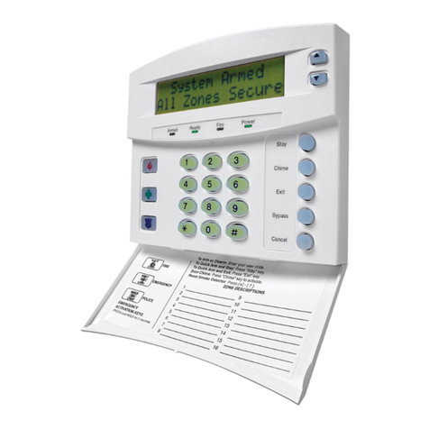
GE Security Vigilant VS1 Product manual

GE
Security
Vigilant Fire & Life Safety
Vigilant VS1 and VS2
Technical Reference Manual
P/N 3101113 • REV 2.0 • ISS 01JUL08

Copyright Copyright © 2008 GE Security, Inc. All rights reserved.
This document may not be copied in whole or in part or otherwise reproduced
without prior written consent from GE Security, Inc., except where specifically
permitted under U.S. and international copyright law.
Document number: 3101113 Revision: 2.0
Disclaimer The information in this document is subject to change without notice.
GE Security, Inc. (“GE Security”) assumes no responsibility for inaccuracies or
omissions and specifically disclaims any liabilities, losses, or risks, personal or
otherwise, incurred as a consequence, directly or indirectly, of the use or application
of any of the contents of this document. For the latest documentation, contact your
local supplier or visit us online at www.gesecurity.com.
This publication may contain examples of screen captures and reports used in daily
operations. Examples may include fictitious names of individuals and companies.
Any similarity to names and addresses of actual businesses or persons is entirely
coincidental.
Trademarks and patents GE and the GE monogram are registered trademarks of General Electric Company.
The Vigilant VS1 and VS2 name and logo are registered trademarks of GE Security.
Other trade names used in this document may be trademarks or registered
trademarks of the manufacturers or vendors of the respective products.
Intended use Use this product only for the purpose it was designed for; refer to the data sheet and
user documentation for details. For the latest product information, contact your
local supplier or visit us online at www.gesecurity.com.
FCC compliance This equipment has been tested and found to comply with the limits for a Class A
digital device, pursuant to part 15 of the FCC Rules. These limits are designed to
provide reasonable protection against harmful interference when the equipment is
operated in a commercial environment. This equipment generates, uses, and can
radiate radio frequency energy and, if not installed and used in accordance with the
instruction manual, may cause harmful interference to radio communications.
You are cautioned that any changes or modifications not expressly approved by the
party responsible for compliance could void the user's authority to operate the
equipment.
The European directive “Waste Electrical and Electronic Equipment” (WEEE) aims to
minimize the impact of electrical and electronic equipment waste on the
environment and human health. To conform with this directive, electrical equipment
marked with this symbol must not be disposed of in European public disposal
systems. European users of electrical equipment must now return end-of-life
equipment for disposal. Further information can be found on the following website:
http://www.recyclethis.info/.

Vigilant VS1 and VS2 Technical Reference Manual i
Content
Important information • iii
Minimum system requirements • vii
To get started • viii
Chapter 1 System operation • 1
Operation overview • 3
LCD display screen • 5
System LEDs • 9
LED display expander LEDs • 10
Control buttons • 11
Component descriptions • 13
Events with event messages • 15
Event ID numbers and descriptions • 17
Viewing event details • 22
Resetting the panel • 23
Silencing panel and annunciator buzzers • 24
Silencing notification appliances • 25
Re-sounding notification appliances • 26
Conducting a lamp test • 27
Activating a device • 28
Restoring a device • 29
Activating a NAC • 30
Restoring a NAC • 31
Disabling a device • 32
Enabling a device • 34
Disabling a zone • 35
Enabling a zone • 37
Disabling a panel event • 38
Enabling a panel event • 40
Disabling a loop event • 41
Enabling a loop event • 43
Disabling a panel NAC • 44
Enabling a panel NAC • 45
Disabling/enabling the dialer and network • 46
Using the drill command • 48
Using the walk test command • 49
Chapter 2 Installation and wiring • 53
Cabinet box installation • 54
Panel electronics installation • 56
Cabinet wire routing • 57
AC power wiring • 58
Panel low voltage wiring • 59
Battery wiring (TB8) • 60
Notification appliance circuit wiring (TB2) • 61
Device loop wiring • 63
Alarm, trouble, and supervisory relay wiring
(TB3) • 65
Remote annunciator wiring (TB4) • 66
Auxiliary/smoke power output wiring (TB3) • 68
SA-DACT wiring • 69
SA-232 wiring • 71
SA-CLA wiring • 74
SA-ETH wiring • 75
CTM module wiring • 76
RPM module wiring • 78
Chapter 3 Programming • 81
UL 864 programming requirements • 83
Getting started • 84
Factory default settings • 87
Setting the time and date • 92
Setting daylight saving time • 93
Setting the passwords • 95
Restoring the factory default settings • 96
Programming the programmable keys • 97
Clearing the history • 100
Restarting the panel • 101
Enabling the RS232 CU Enable command • 102
Contact ID event codes • 103
Auto programming the panel • 107
Advanced programming overview • 112
Programming panel and loop options • 113
Loop configuration options • 115
Correlation groups programming • 116
Device programming • 118
Loop 2 enable • 122
Loop class programming • 123
Mapping programming • 124
Mapping (map mismatch) • 126
Zone programming • 128
Panel configuration options • 130
NAC programming • 131
Annunciator class programming • 133
Annunciator programming • 134
CMS device programming • 136
Dialer programming • 138
Network (receiver) programming • 140
Printer programming • 142
Network card programming • 143
ii Vigilant VS1 and VS2 Technical Reference Manual
Lock remote read programming • 144
AC voltage programming • 145
Panel operation programming • 146
Panel events programming • 148
Loop events programming • 151
Unconfigured alarm programming • 153
Common trouble programming • 155
Incremental programming the panel • 157
Adding a device to a programmed system • 160
Removing a device from a programmed
system • 165
Chapter 4 Reports • 167
History report • 168
Walk Test report • 170
Device Maintenance report • 171
System Status report • 172
Correlation Groups report • 173
Zone report • 174
System Configuration report • 175
Internal Status report • 177
Device Details report • 178
Diagnostics reports • 180
Internal Fault report • 183
Canceling a report • 184
Chapter 5 Diagnostics, maintenance, and
testing • 185
Preventive maintenance schedule • 186
Fast ground check • 187
Recalibrate device • 188
Flash device LED • 189
Loop comm check • 190
Control panel testing • 191
Testing a device (test fire) • 193
SA-DACT testing • 194
Conducting a lamp test • 195
Using the walk test command • 196
Using HyperTerminal • 199
Replacing a device in alarm • 201
Appendix A Panel specifications • 203
Control panel specifications • 204
Appendix B Worksheets • 207
Battery calculation worksheet • 208
Notification appliance circuit calculations
worksheet • 211
Notification appliance voltage drop calculation
worksheet • 217
Device loop maximum wire length
worksheet • 219
Correlation groups worksheet • 225
Device settings worksheet • 226
Loop worksheet • 228
Panel configuration worksheet • 229
Panel operation worksheet • 232
Zone settings worksheet • 233
Appendix C Front panel menu flowcharts • 235
Main menu • 236
Reports menu • 237
Test menu • 238
Control menu • 239
Program menu • 240
Programmable keys menu • 241
Advanced program main menu • 242
Advanced: Loop configuration menu • 243
Advanced: Device configuration menu • 244
Advanced: Panel configuration menu • 245
Advanced: Panel configuration - CMS device
menu • 246
Advanced: Panel operation menu • 247
Advanced: Panel events menu • 248
Advanced: Loop events menu • 249
Advanced: Unconfigured alarm menu • 250
Advanced: Common trouble menu • 251
Auto program menu • 252
Incremental programming menu • 253
Diagnostics menu • 254
Appendix D Applications • 255
Sounder base applications • 256
Appendix E Device types to personality codes
correlation • 263
Device types to personality codes
correlation • 264
Index • 271

Vigilant VS1 and VS2 Technical Reference Manual iii
Important information
Limitation of liability
This product has been designed to meet the requirements of NFPA
72 National Fire Alarm Code, UL 864 Standard for Control Units for
Fire Protective Signaling Systems, and ULC S527 Standard for Control
Units for Fire Alarm Systems. Installation in accordance with this
manual, applicable codes, and the instructions of the authority
having jurisdiction is mandatory. GE Security shall not under any
circumstances be liable for any incidental or consequential
damages arising from loss of property or other damages or losses
owing to the failure of GE Security products beyond the cost of
repair or replacement of any defective products. GE Security
reserves the right to make product improvements and change
product specifications at any time.
While every precaution has been taken during the preparation of
this manual to ensure the accuracy of its contents, GE Security
assumes no responsibility for errors or omissions.
VS1 and VS2 FCC compliance
This equipment can generate and radiate radio frequency energy. If
the equipment is not installed in accordance with this manual, it
may cause interference to radio communications. This equipment
has been tested and found to comply with the limits for Class A
computing devices pursuant to Subpart B of Part 15 of the FCC
Rules. These rules are designed to provide reasonable protection
against such interference when this equipment is operated in a
commercial environment. Operation of this equipment is likely to
cause interference, in which case the user, at his own expense, will
be required to take whatever measures may be required to correct
the interference.
SA-DACT FCC information
Cautions
• To ensure proper operation, this dialer must be installed
according to the enclosed installation instructions. To verify that
the dialer is operating properly and can successfully report an
alarm, it must be tested immediately after installation, and
periodically thereafter, according to the enclosed test
instructions.

iv Vigilant VS1 and VS2 Technical Reference Manual
• In order for the dialer to be able to seize the phone line to report
an alarm or other event when other customer equipment
(telephone, answering system, computer modem, etc.)
connected to the same line is in use, the dialer must be
connected to a properly installed RJ-31X jack. The RJ-31X jack
must be connected in series with, and ahead of, all other
equipment attached to the same phone line. Series installation
of an RJ-31X jack is depicted in the wiring diagram. If you have
any questions concerning these instructions, you should
consult your telephone company or a qualified installer.
Testing
When programming emergency numbers or making test calls to
emergency numbers, remain on the line and briefly explain to the
dispatcher the reason for the call. Perform programming and testing
activities in the off-peak hours, such as early morning or late
evenings.
Compliance
• For equipment approved before July 23, 2001: This dialer
complies with Part 68 of the FCC rules. A label attached to the
dialer contains, among other information, the FCC registration
number and ringer equivalence number (REN) for this
equipment. If requested, this information must be provided to
the telephone company.
For equipment approved after July 23, 2001: This dialer
complies with Part 68 of the FCC rules and the requirements
adopted by the Administrative Council for Terminal
Attachments (ACTA). A label attached to the dialer contains,
among other information, a product identifier in the format
US:AAAEQ##TXXXX. If requested, this information must be
provided to the telephone company.
• The plug and jack used to connect the dialer to the premises
wiring and telephone network must comply with the applicable
FCC Part 68 rules and requirements adopted by ACTA. The dialer
must be connected to a compliant RJ-31X or RJ-38X jack using
a compliant cord. If a modular telephone cord is supplied with
the dialer, it is designed to meet these requirements. See
installation instructions for details.
• A ringer equivalence number (REN) is used to determine how
many devices you can connect to a telephone line. If the total
REN value for all devices connected on a telephone line exceeds
that allowed by the telephone company, the devices may not
ring on an incoming call. In most (but not all) areas the total REN
value should not exceed 5.0. To be certain of the total REN value

Vigilant VS1 and VS2 Technical Reference Manual v
allowed on a telephone line, contact the local telephone
company.
For products approved after July 23, 2001, the REN is part of the
product identifier in the format US:AAAEQ##TXXXX. The digits
## represent the REN without a decimal point. Example: 03 is an
REN of 0.3. For earlier products the REN is listed separately.
• If the dialer is harming the telephone network, the telephone
company will notify you in advance that temporary
discontinuance of service may be required. If advance notice
isn’t practical, the telephone company will notify you as soon as
possible. You will also be advised of your right to file a
complaint with the FCC, if you believe it is necessary.
• The telephone company may make changes to its facilities,
equipment, operations, or procedures that could affect the
operation of the dialer. If this happens, the telephone company
will provide advance notice in order for you to make necessary
modifications to maintain uninterrupted service.
• If you are experiencing problems with the dialer, contact the
manufacturer for repair or warranty information. If the dialer is
harming the telephone network, the telephone company may
request that you disconnect the dialer until the problem is
resolved.
• The dialer contains no user serviceable parts. In case of defects,
return the dialer for repair.
• You may not connect the dialer to a public coin phone or a
party line service provided by the telephone company.
Industry Canada information
Note: The Industry Canada label identifies certified equipment. This
certification means that the equipment meets certain
telecommunications network protective, operational, and safety
requirements. Industry Canada does not guarantee the equipment
will operate to the user’s satisfaction.
Before installing this equipment, users should ensure that it is
permissible to be connected to the facilities of the local
telecommunications company. The equipment must also be
installed using an acceptable method of connection. The customer
should be aware that compliance with the above conditions may
not prevent degradation of service in some situations.
Repairs to certified equipment should be made by an authorized
Canadian maintenance facility designated by the supplier. Any
repairs or alterations made by the user to this equipment, or

vi Vigilant VS1 and VS2 Technical Reference Manual
equipment malfunctions, may give the telecommunications
company cause to request the user disconnect the equipment.
Users should ensure for their own protection that the electrical
ground connections of the power utility, telephone lines, and
internal metallic water pipe system, if present, are connected
together. This precaution may be particularly important in rural
areas.
Note: The Load Number (LN) assigned to each terminal device
denotes the percentage of the total load to be connected to a
telephone loop which is used by the device, to prevent overloading.
The termination on a loop may consist of any combination of
devices subject only to the requirements that the sum of the Load
Numbers of all the devices does not exceed 100.
Caution: Users should not
attempt to make connections
themselves, but should
contact the appropriate
electric inspection authority,
or electrician, as appropriate

Vigilant VS1 and VS2 Technical Reference Manual vii
Minimum system requirements
The table below lists the minimum hardware requirements for each
type of system for which the control panel is listed.
System Equipment needed
Protected Premises (Local) Fire
Alarm System
Control panel
Appropriately sized batteries
Auxiliary Fire Alarm System, Local
Energy Type
Control panel
Appropriately sized batteries
CTM module
Remote Supervising Station Fire
Alarm System
Control panel
Appropriately sized batteries
SA-DACT or RPM module
Central Station Fire Alarm System Control panel
Appropriately sized batteries
SA-DACT or RPM module

viii Vigilant VS1 and VS2 Technical Reference Manual
To get started
If you are just starting out, follow the items in this checklist to
prepare, install, wire, and program your fire alarm control panel.
1. Prepare the site. Make sure the installation location is free from
construction dust and debris and extreme temperature ranges
and humidity.
2. Unpack the equipment.
3. Install the cabinet box. See “Cabinet box installation” for cabinet
dimensions.
4. Install the panel electronics in the cabinet box. See "Panel
electronics installation" for more information.
5. Remove the clear protective plastic from the front panel display.
6. Install the optional panel accessories. See each component's
installation sheet instructions for more information.
7. Review the wire routing. See “Cabinet wire routing.”
8. Connect the field wiring. See the appropriate wiring topics in the
installation and wiring section. Meter for opens, grounds, and
shorts before connecting.
9. Connect AC power and ground wiring. See “AC power wiring.”
The panel cannot be started on batteries only.
10. Connect panel low voltage wiring. See “Panel low voltage
wiring.”
11. Turn on AC power.
12. Connect the batteries. See “Battery wiring.”
13. Program the panel. Refer to "Getting started" in the
programming section. If you are using the configuration utility,
refer to its Help.
14. Test the system for proper operation.
WARNING: Make sure that
the AC power circuit breaker
is off before connecting
wires to the terminal block.

Vigilant VS1 and VS2 Technical Reference Manual 1
Chapter 1
System operation
Summary
This chapter covers the front panel display, operating the panel, and
controlling devices, NACs, and zones.
Content
Operation overview • 3
Front panel display • 3
Control panel operations • 3
LCD display screen • 5
System normal display screen • 5
System off-normal display screen • 6
Event details display screens • 6
System LEDs • 9
LED display expander LEDs • 10
Control buttons • 11
Component descriptions • 13
Events with event messages • 15
Printout examples • 15
Event ID numbers and descriptions • 17
Viewing event details • 22
Resetting the panel • 23
Silencing panel and annunciator buzzers • 24
Silencing notification appliances • 25
Re-sounding notification appliances • 26
Conducting a lamp test • 27
Activating a device • 28
Restoring a device • 29
Activating a NAC • 30
Restoring a NAC • 31
Disabling a device • 32
Enabling a device • 34
Disabling a zone • 35

Chapter 1: System operation
2 Vigilant VS1 and VS2 Technical Reference Manual
Enabling a zone • 37
Disabling a panel event • 38
Enabling a panel event • 40
Disabling a loop event • 41
Enabling a loop event • 43
Disabling a panel NAC • 44
Enabling a panel NAC • 45
Disabling/enabling the dialer and network • 46
Using the drill command • 48
Using the walk test command • 49

Chapter 1: System operation
Vigilant VS1 and VS2 Technical Reference Manual 3
Operation overview
Front panel display
The front panel display is the user interface for the control panel.
The display is comprised of the LCD display, LED indicators, and
control buttons, which are used to operate and program the panel.
Front panel display layout
00:00:00 01/01/07
Control
buttons
L
C
D
display
System
LEDs
System
LEDs
,
Control
buttons
Control panel operations
The control panel operates in either normal mode or off-normal
mode.
Normal mode
The panel operates in normal mode in the absence of any alarm,
supervisory, trouble, or monitor events. In normal mode, the control
panel monitors the system.
Off-normal mode
The panel operates in off-normal mode any time an event is
introduced into the system. When this happens, the panel:
• Changes contact positions on appropriate common relays
• Activates alarm outputs (for alarm events only)

Chapter 1: System operation
4 Vigilant VS1 and VS2 Technical Reference Manual
• Turns on the appropriate LEDs and the panel buzzer
• Executes the appropriate programmed output response for the
input that signaled the event
• Communicates event information to the remote annunciator
• Sends a record of the event to the remote annunciator and to
the control panel's history log
• Transmits event messages to a central monitoring station as
programmed
• Prints event information on the printer if one is connected to the
panel

Chapter 1: System operation
Vigilant VS1 and VS2 Technical Reference Manual 5
LCD display screen
The LCD display is a 4-line by 20-character display that provides the
user interface with the control panel for system programming,
testing, report viewing, and off-normal event notification. The LCD
display has a backlight that turns on when a button is pushed or
when an alarm event takes place in the system. When the panel is
operating on battery power, the backlight automatically turns off
after one minute of inactivity.
System normal display screen
The LCD display shows the system normal display screen when the
control panel is in the normal (quiescent) state. The screen displays
the following:
• Time: Displays the current time
• Date: Displays the current date in month/day/year format
• Login: When you are logged on, "login:" with the password level
is displayed in the top-right of the display, alternating with
other information being displayed in that area of the screen
(e.g. reset)
• Banner area: Nothing is displayed unless custom programmed
(see "Panel operation programming")
LCD display under normal conditions
00:00:00 01/01/07
Banner
Banner continued
Ti
me
D
ate
Banner area
S
ystem logi
n
indication
00:00:00 Login:2

Chapter 1: System operation
6 Vigilant VS1 and VS2 Technical Reference Manual
System off-normal display screen
During an off-normal event, such as an alarm, supervisory, monitor,
trouble, prealarm, alarm verify, disablement, or test, the LCD screen
changes to display important information about the event. The
screen displays the following:
• Time: Displays the current time
• Active points: Indicates the number of active points in the
system. Increments or decrements per the activations and
restorals of devices. Toggles with "login:" when you are logged
on.
• Disabled points: Indicates the number of disabled points in the
system. Toggles with "login:" when you are logged on and
"reset" if the panel is being reset.
• Event number: The event number (active point number) in queue
• Event type message: The event message for the type of event
taking place
• Device label: The label for the device, either the default label or
a custom programmed label
LCD display under off-normal conditions
00:00:00 A001 D001
001 Alarm Active
Computer room closet
Floor 1
Time
A
ct
i
ve po
i
nts
Disabled
points
Event
number
Event type
message
Device
label
Event details display screens
The off-normal events that take place in your system contain event
information, which is displayed on the LCD display screen.
Additional information is also available for the event, which is
displayed on a secondary screen. The screen displays the following
information based on the type of event that takes place:
• Loop number: The loop the device is on
• Device number: The device address (number)
• Device type: The type of device, which was assigned in
programming
• Serial number: The serial number assigned to the device
• Internal event number: See "Event ID numbers and descriptions"

Chapter 1: System operation
Vigilant VS1 and VS2 Technical Reference Manual 7
• Zone number and device label for devices in zones
• Annunciator number and label
• Other information when it is available
Device event details display screen
Loop 1 Device 001
Smoke
Ser#3333333333
Loop
number
Device
number
Device
type Serial
number
Internal event (panel and loop events) details display screen
Internal Event 021
I
nterna
l
event num
b
er
Note: See "Event ID numbers and descriptions" for a list of event
numbers.
Zone event details display screen
Zone 01
Lobby pull station
Z
one num
b
er
Label
Note: You can scroll through the list of all devices in the zone
reporting an event.
Annunciator event details display screen
Annunciator 007
Annunciator 007
A
nnunc
i
ator num
b
er
Label

Chapter 1: System operation
8 Vigilant VS1 and VS2 Technical Reference Manual
To access the event details screen:
1. When an event takes place, press Enter on the front panel.
2. View the event details.
The event details screen is displayed for 15 seconds and then
returns to the previous screen if there is no activity.
Enter button
Enter butto
n

Chapter 1: System operation
Vigilant VS1 and VS2 Technical Reference Manual 9
System LEDs
LEDs indicate system events and system operation.
LED Description
Fire Alarm Red LED. Flashes when there is an active alarm
event on any loop. On steady once
acknowledged.
Trouble Yellow LED. Flashes when there's a fault with a
monitored circuit or system component or
when a circuit is disabled. On steady once
acknowledged.
Sup Yellow LED. Flashes when there is an active
supervisory event on any loop. On steady once
acknowledged.
AC Power Green LED. On when the panel has AC power.
Disable Yellow LED. Double-flashes when there is a
disabled circuit or alarm relay.
Ground Fault Yellow LED. On steady during an active ground
fault.
Test Yellow LED. Flashes when performing an
audible walk test. Steady indicates a silent test.
Monitor Yellow LED. Flashes when there is an active
monitor event on any loop. On steady once
acknowledged.
Service Detector Yellow LED. Indicates that detector needs
servicing.
Signal Silence Yellow LED. On steady indicates that NAC
circuits are turned off but the panel is still in
alarm.
Remote Disconnect Yellow LED. On steady indicates that the CMS
devices (dialer and network card) are disabled
or that the alarm relay is enabled or disabled
when the dialer is set to modem only.
Drill Yellow LED. Indicates that the panel is in drill.
Reset Yellow LED. Indicates that the panel is going
through a reset.
Panel Silence Yellow LED. Indicates that the panel has been
silenced during an active trouble, supervisory,
monitor, or alarm event and indicates that new
event activations have been acknowledged.
User keys Yellow LED. Indicates the programmed key
function is active.

Chapter 1: System operation
10 Vigilant VS1 and VS2 Technical Reference Manual
LED display expander LEDs
The D16L-VS LED Display Expander provides LED annunciation for
up to 16 zones. The expander provides two LEDs for each zone. Two
LED display expanders can be installed in the panel.
LED operation zones 1 through 12 (and 17 through 28 if the second
LED expander is installed)
• LED 1 - Alarm: Red LED flashes
• LED 2 - Trouble: Yellow LED flashes
LED operation zones 13 through 16 (and 29 through 32 if the
second LED expander is installed)
• LED 1 - Bicolor
Alarm: Red LED flashes
Non-alarm active: Yellow LED flashes
• LED 2 - Trouble: Yellow LED flashes
LED zone designations
Zone 16
Zone 13
Zone 32
Zone 29
Zone 1 Zone 17
LED
expander 1
LED
expander 2
LED 1
LED 2 Alarm/Non-alarm
and trouble
zone LEDs
Other manuals for Vigilant VS1
1
This manual suits for next models
1
Table of contents
Other GE Security Control Panel manuals

GE Security
GE Security 1200C User manual

GE Security
GE Security Simon XT User manual

GE Security
GE Security 1501 User manual

GE Security
GE Security ZP3 Instruction Manual

GE Security
GE Security 1200C User manual

GE Security
GE Security NetworX Series NX-8V2 User manual

GE Security
GE Security NX-1750 ProxPad User manual

GE Security
GE Security NetworX Series Installation manual