Wiring the Control Panel Operations
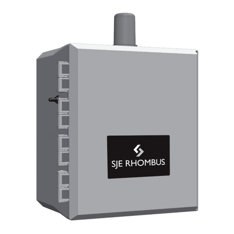
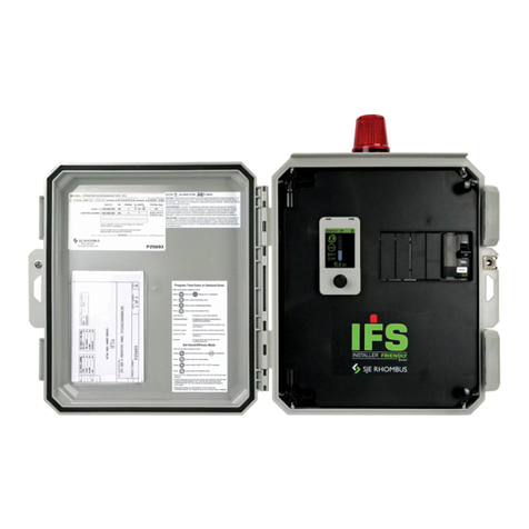
SJE Rhombus Model 322 Three Phase Duplex control panel
operates with oat switches. When all oats are in the
open or OFF position, the panel is inactive. As the liquid
level rises and closes the STOP oat, the panel remains
inactive until the LEAD oat closes. At this point the LEAD
pump will turn ON (if the Hand-O-Auto switch is in the
AUTO mode and the power is ON). The pump will remain
ON until both the STOP and LEAD oats return to their OFF
positions. If the liquid level rises beyond both the STOP
and LEAD oats to reach the LAG oat, the lag pump will
turn ON (if the Hand-O-Auto switch is in the AUTO mode
and the power is ON). Both pumps will remain ON until the
STOP, LEAD, and LAG oats return to their OFF positions.
If the liquid level rises to reach the ALARM oat, the alarm
will be activated.
Alarm System (Indicator Light and Horn)
When an alarm condition occurs, the red light and horn will
be activated.
If the TEST/NORMAL/SILENCE switch is moved to the
SILENCE position and released, the horn will be silenced.
When the alarm condition is cleared, the alarm system is
reset.
Motor Protective Switches
Each pump circuit has motor protective switches that
provides pump disconnect, overload, and branch circuit
protection. Adjust overload to pump FLA.
Hand-O-Auto (HOA) Switches
The HOA 3-way switches control pump functions.
In HAND mode, the pump will turn ON.
OFF turns the pump OFF.
In AUTO mode, commands from the oat switches
turn each pump ON and OFF.
Motor Contactors
Motor contactors control pumps by switching electrical lines.
Transformer
The transformer converts incoming three phase power to
120V to be used for control and alarm.
Auxiliary Contact
Form C - Can be wired normally open or normally closed.
1Determine conduit entrance locations on control panel as shown.
Check local codes and schematic on the inside cover of the panel
for the number of power circuits required.
Be sure the pump power voltage and phase are the same as the
pump motor being installed.
2Connect the following wires to the proper terminal positions:
• incoming power
• pump 1
• pump 2
• oat switches
See schematic on inside cover of the control panel for details.
Technical support,
service questions:
+1-800-Rhombus
(+1-800-746-6287)
Monday - Friday
7:00 AM to 6:00 PM Central Time
?
3Verify correct operation of control panel after installation is
complete.
3
Type 4X conduit must be used to maintain a Type 4X rating of
the control panel.
Incoming
Power
Pumps
You must use conduit sealant to prevent
moisture or gases from entering the panel.
1-2 ALT 2-1
SF2
25K
5K NC
150K
125K50K
15K
LEAD / LAG
STOP LEAD LAG ALARM
PUMP 1
H
O
A
NO C N C
OFF ON
TEST TEST TEST TEST
POWER
34
12
5678910
AUX
PUMP 2
H
O
A
22650 County Highway 6
Detroit Lakes, MN 56501 USA
Tel: 218-847-1317
Web: www.sjerhombus.com
Transformer
Auxiliary Contact
Float
Switches
Typical Layout
(May vary with
options ordered).
