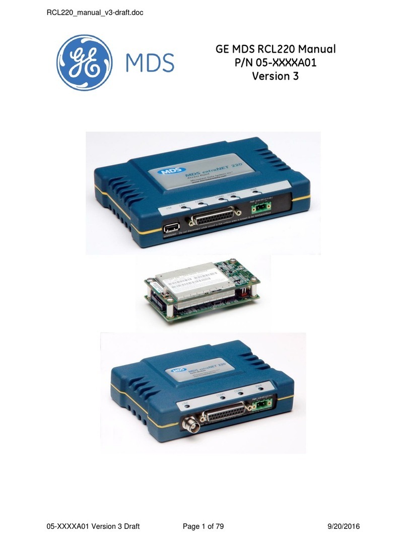
GE MDS TransNEXT NET9L User manual

MDS™TransNEXT
MDS TransNEXT Technical Manual, Rev. A
December 2023
Technical Manual
Technical Manual`

ii MDS TransNEXT Technical Manual MDS 05-7280A01, Rev. A
TABLE OF CONTENTS
COPYRIGHT AND TRADEMARK................................................................................................................4
RF REGULATORY INFORMATION.............................................................................................................4
SAFETY REGULATORY INFORMATION ...................................................................................................9
1.0 PRODUCT OVERVIEW AND APPLICATIONS .............................................................................10
1.1 INTRODUCTION ..............................................................................................................................10
ABOUT THIS MANUAL ...............................................................................................................................10
2.0 PRODUCT DESCRIPTION.............................................................................................................12
2.1 KEY FEATURES..............................................................................................................................12
2.2 TYPICAL APPLICATIONS..................................................................................................................12
2.3 TRANSNEXT CONNECTORS AND INDICATORS.................................................................................14
2.4 GROUNDING CONSIDERATIONS.......................................................................................................19
2.5 MOUNTING OPTIONS......................................................................................................................19
OPTIONAL DIN RAIL MOUNTING ................................................................................................................20
2.6 ANTENNA PLANNING AND INSTALLATION..........................................................................................20
2.7 INITIAL SETTINGS OVERVIEW..........................................................................................................21
SETTING BASIC PARAMETERS—FIRST STEPS.............................................................................................21
3.0 DEVICE MANAGEMENT................................................................................................................22
3.1 USING THE WEB USER INTERFACE..................................................................................................22
3.2 USING THE COMMAND LINE INTERFACE (CLI)..................................................................................28
DIFFERENCES BETWEEN USB, SERIAL AND SSH ........................................................................................28
ESTABLISHING COMMUNICATION—SSH....................................................................................................28
ESTABLISHING COMMUNICATION—USB....................................................................................................29
ESTABLISHING COMMUNICATION—SERIAL INTERFACE .................................................................................29
CLI OVERVIEW ........................................................................................................................................30
3.3 DEVICE CONFIGURATION................................................................................................................32
OVERVIEW...............................................................................................................................................32
RADIO SETTINGS ......................................................................................................................................34
OWNER SETTINGS ....................................................................................................................................37
SYSTEM SETTINGS ...................................................................................................................................37
DISPLAY SETTINGS ...................................................................................................................................38
ETH SETTINGS .........................................................................................................................................38
COM1 SETTINGS .....................................................................................................................................39
IPPL SETTINGS .........................................................................................................................................41
DLINK SETTINGS.......................................................................................................................................42
PASSWORD SETTINGS...............................................................................................................................43
3.4 SYSTEM HEALTH AND STATUS........................................................................................................44
SHOW COMMAND .....................................................................................................................................44
EVENT LOGGING ......................................................................................................................................44
SNAPSHOTS AND SYSTEM RECOVERY ........................................................................................................45
3.5 FIRMWARE REPROGRAMMING.........................................................................................................45
LOCAL DEVICE REPROGRAMMING ..............................................................................................................45
OVER-THE-AIR REPROGRAMMING..............................................................................................................48

iii MDS TransNEXT Technical Manual MDS 05-7280A01, Rev. A
4.0 TECHNICAL REFERENCE ............................................................................................................50
4.1 AWORD ABOUT RADIO INTERFERENCE ..........................................................................................50
4.2 TROUBLESHOOTING .......................................................................................................................51
LED STATUS INDICATORS.........................................................................................................................51
EVENT LOG .............................................................................................................................................51
SETUP MODE...........................................................................................................................................51
4.3 TECHNICAL SPECIFICATIONS ..........................................................................................................53
5.0 GLOSSARY OF TERMS AND ABBREVIATIONS.........................................................................56
6.0 APPENDIX A –ELECTRONIC INK DISPLAY................................................................................59
6.1 INTRODUCTION ..............................................................................................................................59
6.2 STATUS PAGE................................................................................................................................59
6.3 ANTENNA ALIGNMENT PAGE...........................................................................................................59
6.4 SPECTRUM ANALYZER PAGE..........................................................................................................60
7.0 APPENDIX B –OPERATING FREQUENCIES..............................................................................62
8.0 APPENDIX C–LICENSES .............................................................................................................63
8.1 OPEN SOURCE LICENSE DECLARATION...........................................................................................63
9.0 APPENDIX D –COUNTRY SPECIFIC INFORMATION................................................................64
10.0 APPENDIX E –ALARM CODES....................................................................................................65

4 MDS TransNEXT Technical Manual MDS 05-7280A01, Rev. A
Copyright and Trademark
This manual and all software described herein is protected by Copyright: 2023 GE MDS LLC. All rights
reserved. GE MDS LLC reserves its right to correct any errors and omissions in this publication.
RF Regulatory Information
RF Exposure Notice (English and French)
Concentrated energy from a directional antenna may pose a health hazard to humans.
Do not allow people to come closer to the antenna than the distances listed in the
table below when the transmitter is operating. More information on RF exposure can
be found online at the following website:
www.fcc.gov/oet/info/documents/bulletins
Concentré d'énergie à partir d'une antenne directionnelle peut poser un risque pour
la santé humaine. Ne pas permettre aux gens de se rapprocher de l'antenne que les
distances indiquées dans le tableau ci-dessous lorsque l'émetteur est en marche. Plus
d'informations sur l'exposition aux RF peut être trouvé en ligne à l'adresse suivante:
www.fcc.gov/oet/info/documents/bulletins
Antennas must not be co-located. All transmission antennas must be at least 20 cm apart to comply with
FCC co-location rules.
TransNEXT Minimum RF Safety Distance
TransNEXT
Model
Minimum Safety Distance
from Antenna
operating with a 10dBd (12.15dBi) antenna and so
configured for the maximum allowable EiRP of +36dBm
NET9L
34 cm
NET9S
34 cm
l’exposition aux RF
RF Exposure

MDS 05-7280A01, Rev. A MDS TransNEXT Technical Manual 5
Approved Antennas
This product has been approved for use with the antennas listed in Table 1-1, below:
Table 1-1. Approved Antennas for TransNEXT
Professional installation is required. The installation site must conform to 15.247/RSS-247 Conducted
and Radiated Power limits. Proper feedline selection and/or radio power setpoints must be set
accordingly for use with each antenna type as detailed in Table 1-2.
Table 1-2. Feedline losses and radio power setpoints for ERP and Conducted Power compliance for
TransNEXT installations.

6 MDS TransNEXT Technical Manual MDS 05-7280A01, Rev. A
FCC Part 15 Notice and Industry Canada RSS Notices
This device complies with Part 15 of the FCC rules for a Class A digital device. Operation of this device
subject to the following two conditions:
(1) this device may not cause harmful interference, and
(2) this device must accept any interference received, including interference that may cause
undesired operation. Any unauthorized modification or changes to this device without the express
approval of the manufacturer may void the user’s authority to operate this device. Furthermore,
this device is intended to be used only when installed in accordance with the instructions outlined
in this guide. Failure to comply with these instructions may void the user’s authority to operate
this device.
(a) Under Industry Canada regulations, this radio transmitter may only operate using an antenna of a type
and maximum (or lesser) gain approved for the transmitter by Industry Canada. To reduce potential
radio interference to other users, the antenna type and its gain should be so chosen that the equivalent
isotropically radiated power (e.i.r.p.) is not more than that necessary for successful communication.
(b) The radio transmitters described herein (IC ID: 101D-NET9L and 101D-NET9S) have been approved
by Industry Canada to operate with the antenna types listed in Table 1-1 with the maximum
permissible gain and required antenna impedance for each antenna type indicated. Antenna types not
included in this list, having a gain greater than the maximum gain indicated for that type, are strictly
prohibited for use with this device.
Cet appareil est conforme à la Partie 15 des règlements de la FCC et Industrie Canada exempts de licence
standard RSS (s). Son utilisation est soumise à deux conditions:
(1) ce dispositif ne peut causer des interférences,
(2) cet appareil doit accepter toute interférence pouvant causer un mauvais fonctionnement du
dispositif.
(a) En vertu des règlements d'Industrie Canada, cet émetteur radio ne peut fonctionner avec une antenne
d'un type et un maximum (ou moins) approuvés pour gagner de l'émetteur par Industrie Canada. Pour
réduire le risque d'interférence aux autres utilisateurs, le type d'antenne et son gain doivent être
choisies de façon que la puissance isotrope rayonnée équivalente (PIRE) ne dépasse pas ce qui est
nécessaire pour une communication réussie.
(b) Les émetteurs radio décrits ici (IC ID : 101D-NET9L et 101D-NET9S) ont été approuvés par
Industrie Canada pour fonctionner avec les types d'antennes répertoriés dans le tableau (Table 1-1)
avec le gain maximum autorisé et l'impédance d'antenne requise pour chaque type d'antenne indiqué.
Les types d'antennes non inclus dans cette liste, ayant un gain supérieur au gain maximum indiqué
pour ce type, sont strictement interdits pour une utilisation avec cet appareil.
IEEE-1613 Compliance
The TransNEXT is IEEE-1613 compliant provided that unshielded cables are <= 2 meters in length.
Operational Safety Notices
The TransNEXT may not be used in an environment where radio frequency equipment is prohibited or
restricted in its use. This typically includes aircrafts, airports, hospitals, and other sensitive electronic
areas.

MDS 05-7280A01, Rev. A MDS TransNEXT Technical Manual 7
Do not operate RF devices in an environment that may be susceptible to radio interference resulting in
danger, specifically:
•Areas where prohibited by law - Follow any special rules and regulations and obey all signs and
notices. Do not use the TransNEXT when you suspect that it may cause interference or danger.
•Near Medical and life support equipment - Do not use the TransNEXT in any area where medical
equipment, or life support equipment may be located, or near any equipment that may be susceptible
to any form of radio interference.
•All cables and conductors making connections to the units need to be rated at 85 °C or higher.
•Use Copper Conductors Only
•Use 18 AWG wire
NOTE The TransNEXT does not support Voice Communications.
Regulatory Limitations
Some product options including hardware and software configuration settings may be restricted based on
applicable region-specific regulatory constraints.
FCC / IC IDs
As of the printing date, the following identifiers are assigned to the models listed below.
Model
FCC ID
IC ID
NET9L
E5MDS-NET9L
101D-NET9L
NET9S
E5MDS-NET9S
101D-NET9S
Country-Specific Installation Data
Refer to APPENDIX D –Country Specific Information at the back of this manual for important notices
regarding installation in specific countries.
Servicing Precautions
No user-serviceable parts are contained inside this equipment. Opening of the unit by unauthorized
personnel voids the warranty. All servicing must be performed by an authorized repair facility.
When servicing energized equipment, be sure to wear appropriate Personal Protective Equipment (PPE).
During internal service, situations could arise where objects accidentally contact or short circuit
components and the appropriate PPE would alleviate or decrease the severity of potential injury. When
servicing equipment, all workplace regulations and other applicable standards for live electrical work
should be followed to ensure personal safety.

8 MDS TransNEXT Technical Manual MDS 05-7280A01, Rev. A
Manual Revision and Accuracy
This manual was updated to cover a specific version of firmware code. Accordingly, some screens and
features may differ from the actual unit you are working with. While every reasonable effort has been
made to ensure the accuracy of this publication, product improvements may also result in minor
differences between the manual and the product shipped to you. If you have additional questions or need
an exact specification for a product, please contact GE MDS using the information at the back of this
guide. In addition, manual updates can be found on our website at www.gemds.com .
Environmental Information
The manufacture of this equipment has required the extraction and use of natural resources. Improper
disposal may contaminate the environment and present a health risk due to hazardous substances
contained within. To avoid dissemination of these substances into our environment, and to limit the
demand on natural resources, we encourage you to use the appropriate recycling systems for disposal.
These systems will reuse or recycle most of the materials found in this equipment in a sound way. Please
contact GE MDS or your supplier for more information on the proper disposal of this equipment.
Cyber Security Policy
As part of GE’s commitment to product safety, quality and reliability and to reduce risk exposure for GE
and our customers, the “GE Product Cyber Security Standard” (the Policy) outlines the requirements that
GE Business Units must meet. The Policy, requires each GE Business Unit to implement reasonable,
industry-specific measures designed to protect all GE products and services, including all relevant
components and services sourced from third parties, from cyber security threats throughout their
supported life cycle.

MDS 05-7280A01, Rev. A MDS TransNEXT Technical Manual 9
Safety Regulatory Information
CSA/us C1D2 Safety Notice
This product is approved for use in Class 1, Division 2, Groups A, B, C & D Hazardous Locations. Such
locations are defined in Article 500 of the National Fire Protection Association (NFPA) publication
NFPA 70, otherwise known as the National Electrical Code. The transceiver has been recognized for use
in these hazardous locations by the Canadian Standards Association (CSA) which also issues the US mark
of approval (CSA/US). The CSA Certification is in accordance with CSA STD C22.2 No. 213-M1987.
For Class I, Division 2, the product shall be installed in a tool secured enclosure providing a suitable
degree of protection against deterioration of the equipment that would adversely affect its suitability for
use in the hazardous locations area and to avoid USB-C diagnostic port /connectors from being accessible
during normal operation. The antenna port shall be used with a passive antenna only. The final installation
is subject to acceptance of CSA International or the local inspection authority having jurisdiction.
WARNING –EXPLOSION HAZARD. DO NOT REMOVE OR REPLACE WHILE CIRCUIT IS LIVE
UNLESS THE AREA IS FREE OF IGNITIBLE CONCENTRATIONS
WARNING –EXPLOSION HAZARD. DO NOT CONNECT OR DISCONNECT WHEN ENERGIZED
AVERTISSEMENT –RISQUE D'EXPLOSION. NE PAS RETIRER OU REMPLACER LORSQUE LE
CIRCUIT EST SOUS TENSION À MOINS QUE LA ZONE NE SOIT EXEMPTE DE
CONCENTRATIONS INFLAMMABLES
AVERTISSEMENT –RISQUE D'EXPLOSION. NE PAS CONNECTER OU DÉCONNECTER
LORSQU'IL EST SOUS TENSION

10 MDS TransNEXT Technical Manual MDS 05-7280A01, Rev. A
1.0 Product Overview and Applications
1.1 Introduction
This manual describes the MDS TransNEXT ™. The TransNEXT is the successor to the MDS
TransNET™900 MHz unlicensed radio. Setting the standard for reliable, long-range wireless serial data
transmission utilizing proven Frequency Hopping Spread Spectrum (FHSS) technology, the next
generation TransNEXT is backwards-compatible with its predecessor, TransNET. The TransNEXT’ s
backwards compatibility enables the continued use of legacy serial networks while also adding new
capabilities to migrate networks with secure Ethernet connectivity.
Figure 1-1. TransNET Lite
(model NXT9L)
Figure 1-2. Figure 1-3. TransNET Standard with Display
(model NXT9S)
Information on other GE MDS products can be found by visiting our website at www.gemds.com.
About This Manual
This manual is intended for systems engineers, network administrators and others responsible for
planning, commissioning, installing, using and troubleshooting the wireless system. Electronic copies of
all user documentation are available free of charge at www.gemds.com
Software Command Notations
The product is designed for software control via a connected PC. To show the names of software
commands, keyboard entries, or other information displayed on a PC screen, a bolded font is used
throughout the manual. In some cases italics or non-bolded sections may be used to distinguish fixed
syntax from portions of a command where the user must supply specific data.

MDS 05-7280A01, Rev. A MDS TransNEXT Technical Manual 11
For example:
[1234567] Login: admin
NOTE The software commands and responses shown in this manual were obtained from a unit
operating in a lab environment. The information displayed may differ from field service
conditions.

12 MDS TransNEXT Technical Manual MDS 05-7280A01, Rev. A
2.0 Product Description
The TransNEXT is a rugged license-free wireless communication device well suited for a variety of
SCADA and telemetry solutions using serial and IP/Ethernet.
2.1 Key Features
TransNEXT units include the following key features:
•Backwards-Compatible –Over-the-Air Compatible with TransNET, with similar or better RF
performance in real-world field installations.
•Over-the-air (OTA) reprogramming –This facility provides a simple means to non-intrusively
broadcast a firmware upgrade to an entire field of remotes, using a copy of the firmware image
currently running in the TransNEXT master radio. This feature operates slowly to avoid conflicting
with payload data and to allow interoperability through an existing TransNET network.
•Optional E-ink display (select models only)–This display provides a convenient tool for
installation, local diagnostics, and troubleshooting. The E-ink display maintains the last screen
image following a power failure.
•IP Payload –First introduced in the MDS SD™this facility performs local ethernet to serial
conversion, providing an efficient means to connect compatible ethernet devices.
•Small Form Factor—The unit is housed in a rugged enclosure suited for operation in harsh
industrial environments. It requires only protection from direct exposure to the weather and may be
easily mounted inside a NEMA enclosure for outdoor applications when required.
•User Interface—Multiple user interfaces are provided for configuration and monitoring of the unit.
These include USB, web, SSH and local serial (using “+++” to temporarily override the payload
data interface)
NOTE The TransNEXT is designed for secure environments. As such, management of the device does
not support Telnet, but instead implements the more secure SSH protocol.
NOTE For units certified and installed in hazardous locations, use only the serial or Ethernet
connections on the unit’s front panel. Do not use the USB port in hazardous locations.
•Network Management System—TransNEXT is supported by GE MDS PulseNET, a Network
Management System (NMS), providing monitoring of small- and large-scale deployment of all GE
MDS devices. (*** for interoperability, TransNEXT appears as a TransNET device)
2.2 Typical Applications
MDS TransNEXT is the successor to the MDS TransNET radio. It builds on the flexibility of the
predecessor product and serves a wide variety of traditional applications.
Multiple Address Systems (MAS)
This is the most common application of the transceiver. It consists of a central control station (Master)
and two or more associated Remote units. An MAS network provides communications between a central
host computer and remote terminal units (RTUs) or other data collection devices. The operation of the
radio system is transparent to the computer equipment. When used in this application, the transceiver
provides an excellent alternative to traditional (licensed) MAS radio systems.

MDS 05-7280A01, Rev. A MDS TransNEXT Technical Manual 13
Point-to-Point System
A point-to-point configuration is a simple arrangement consisting of just two radios—a Master and a
Remote. This provides a half-duplex communications link for the transfer of data between two locations.
Adding a Tail-End Link to an Existing Network
A tail-end link can be used to extend the range of a traditional (licensed) MAS system. This might be
required if an outlying site is blocked from the MAS Master station by a natural or man-made obstruction.
In this arrangement, a TransNEXT radio links the outlying Remote site into the rest of a licensed MAS
system by sending data from that site to an associated TransNEXT installed at one of the licensed Remote
sites.
As the data from the outlying site is received at the licensed Remote site, it is transferred to the licensed
radio (via a local cable connection) and is then transmitted to the MAS Master station in the usual
manner.
Extending a TransNEXT Network with a Network Repeater
Similar to a Tail-End Link, Store-and-Forward (SAF) offers a way to physically extend the network
range, but in a simple and economical manner. SAF works by dividing a network into a vertical hierarchy
of two or more sub-networks. Extension radios (designated in TransNEXT as radio.mode “x”) serve as
single-radio repeaters that link adjacent sub-networks, and move data from one sub-network to the next
one.
Interworking with a TransNET network
Each of the application types above can be supported by introducing a TransNEXT radio into an existing
TransNET network, replacing older radios or extending communication and new features to new sites.
Figure 2-1. Mixed TransNEXT & TransNEXT Application

14 MDS TransNEXT Technical Manual MDS 05-7280A01, Rev. A
2.3 TransNEXT Connectors and Indicators
Figure 2-2 shows the unit’s front panel connectors and indicators. These items are referenced in the text
that follows. The unit’s LED Indicator / Button Panel is described in Figure 2-6.
.
Figure 2-2. TransNEXT, Connectors and Indicators
PWR & I/O —Two-conductor DC input connection and I/O
-A latching 6-pin connector is used (Figure 2-3). It is keyed and can only be inserted one way.
-Pin 1 is GND, Pin 5 is Vin.
-Pins 2,4, and 6 are reserved for future I/O capability.
-Use Copper Conductors Only
-Use 18 AWG wire
-Tighten wire clamps to 5 lb-in. (0.6 Nm)
Power & I/O
Figure 2-3. 6-pin Power & I/O Connector (P/N 73-1194A85)
Figure 2-4. 6-pin Power & I/O Connector (Phoenix Contact part)
NOTE The unit is designed for use in negative ground DC power systems only. Only use the power
supply provided by the manufacturer for the product or a certified LPS power supply rated for

MDS 05-7280A01, Rev. A MDS TransNEXT Technical Manual 15
nominal power 6-36 VDC, 1.6 A maximum must be used. Otherwise, safety of the product may
be impaired. In case of doubt, please consult the local authorized suppliers.
Input voltage to the unit must be well filtered and within the nominal range of 6-36 VDC. The maximum
rated power consumption of the device is 10 watts, but actual power is typically much less. The power
supply must be capable of supplying the expected maximum power for the installation. For expected
power requirements in common configurations, see “Technical Specifications
on Page 53.
ETH—Ethernet connection port. These ports support both device management and payload data
transport. This is a standard RJ-45 jack and features MDIX auto-sensing capability, allowing straight-
through or crossover cables to be used.
Connecting to the unit via SSH supports device management and provides a similar user interface
available using the unit’s serial COM port.
(As viewed from the outside the unit)
Table 2-1. ETH1/2 Pin Details
Pin
Function
Pin
Function
1
Transmit Data (TX) High
5
Unused
2
Transmit Data (TX) Low
6
Receive Data (RX) Low
3
Receive Data (RX) High
7
Unused
4
Unused
8
Unused
USB Port—This port provides a USB-C connection to a laptop or PC. The port provides a local console
for management of the device. A standard host-to-USB-C cable may be used.
COM Port—This connector serves as the serial interface port for payload data. The COM port serves as
the primary interface for connecting the unit to an external DTE serial device supporting RS-232 or RS-
485. If necessary, an adapter may be used to convert the unit’s RJ-45 serial jack to a DB-9F type (GE
MDS 73-2434A25).
NOTE TransNEXT typically uses the unit’s USB port to access the device management interface
(CLI). As an alternat access method typing “+++” on the COM port (at roughly half second
intervals) will cause it to drop out of payload mode and present the CLI interface. Issuing a
logout command will revert the unit to payload data mode.
The COM port supports a serial data rate of 1200-115200 bps (115200 default, asynchronous only). The
unit is hardwired as a DCE device.

16 MDS TransNEXT Technical Manual MDS 05-7280A01, Rev. A
Supported data formats for the COM port are:
com1.databits
com1.paritybits
com1.stopbits
8N1 - 8 char bits, no parity, 1 stop bit (Default)
8
“N”
1
8N2 - 8 char bits, no parity, 2 stop bits
8
“N”
2
8O1 - 8 char bits, odd parity, 1 stop
8
“O”
1
8O2 - 8 char bits, odd parity, 2 stop bits
8
“O”
2
8E1 - 8 char bits, even parity, 1 stop bit
8
“E”
1
8E2 - 8 char bits, even parity, 2 stop bits
8
“E”
2
The tables on the following page provide pin descriptions for the COM data port in RS-232 mode and
RS-485 modes, respectively.
(As viewed from the outside the unit)
Table 2-2. COM Port Pin Details (RS-232)
Pin
Number
Input / Output
Pin Description
1
OUT
ALARM Output
2
OUT
DCD (Data Carrier Detect)
3
Reserved
--
4
Ground
Connects to ground (negative supply potential) on chassis
5
OUT
RXD (Received Data)—Supplies received data to the connected device
6
IN
TXD (Transmitted Data)—Accepts TX data from the connected device
7
OUT
CTS (Clear to Send)
8
IN
RTS (Request to Send)

MDS 05-7280A01, Rev. A MDS TransNEXT Technical Manual 17
Table 2-3. COM1 Port Pin Details (RS-485)
Pin
Number
Input/Output
Pin Description
1
OUT
ALARM Output
2
OUT
DCD (Data Carrier Detect)
3
Reserved
--
4
Ground
Connects to ground (negative supply potential) on chassis
5
OUT
TXD+/TXB (Transmitted Data +)—Non-inverting driver output. Supplies
received payload data to the connected device.
6
IN
RXD+/RXB (Received Data +) —Non-inverting receiver input. Accepts
payload data from the connected device.
7
OUT
TXD-/TXA (Transmitted Data -)—Inverting driver output. Supplies
received payload data to the connected device.
8
IN
RXD-/RXA (Received Data -) —Inverting receiver input. Accepts
payload data from the connected device.
COM1 Port notes and wiring arrangements (for RS-485)
•The COM1 port supports 4-wire and 2-wire RS-485 mode as follows:
-RXD+ / RXB and RXD–/ RXA are data sent into the unit
-RXD+ / RXB is positive with respect to RXD–/ RXA when the line input is a “0”
-TXD+ / TXB and TXD–/ TXA are data sent out by the unit
-TXD+ / TXB is positive with respect to the TXD–/ TXA when the line output is a “0”
•2-wire RS-485 mode connections:
-Connect pins 5&6 (TXD+/RXD+) together and connect to (TXD+/RXD+) tied together on
connected device
-Connect pins 7&8 (RXD-/TXD-) together and connect to (TXD-/RXD-) tied together on
connected device
•4-wire RS-485 mode connections:
-Connect pin 5 (TXD+) to RXD+ of connected device
-Connect pin 6 (RXD+) to TXD+ of connected device
-Connect pin 7 (TXD-) to RXD- of connected device
-Connect pin 8 (RXD-) to TXD- of connected device
Figure 2-5 illustrates the 2-wire and 4-wire connections described above.
Figure 2-5. EIA-485 4-Wire/2-Wire Connections

18 MDS TransNEXT Technical Manual MDS 05-7280A01, Rev. A
NOTE GE MDS part number 73-2434A25 provides a custom RJ45 to DB9 Adapter for use with the
TransNEXT and other GE MDS products. The chart below provides details for connections
made using this adapter.
WIRING CHART
RJ-45 PIN
FUNCTION
DB9 PIN
1
DSR
6
2
DCD
1
3
DTR
4
4
GND
5
5
RXD
2
6
TXD
3
7
CTS
8
8
RTS
7
LED / Button Panel —The LEDs on the top of the unit provide visual indications of device status. The
push button (appearing like a thin white circle) is used for special functions like controlling the optional
E-ink display screen.
Figure 2-6. LED Indicators & Push Button

MDS 05-7280A01, Rev. A MDS TransNEXT Technical Manual 19
The LEDs are multi-color to convey different types of status conditions as shown in the following chart:
Table 2-4. Description of LED Status Indicators
LED Name
LED State
Description
PWR
(DC Power)
Off
Solid Green
Flashing Red
(0.5s ON/ 0.5s OFF)
Flashing Green
(0.5s ON/ 0.5s OFF)
Fast Alternating
(Red/Yellow/Green)
No power to unit.
Unit is powered, no problems detected.
Alarm indication.
Unit is being programmed.
Unit is booting up.
RADIO-1 (master)
(remote)
(all)
Off
Solid Green + flicker
Solid Color + flicker on data
[Color based on RSSI]Green:
Yellow:
Violet:
Red:
Flashing Red
(1.0s ON/1.0s OFF)
Multi-Color (rotating)
(1.0s ON per color)
Interface disabled.
Radio-1 will flicker on data.
Radio-1 is synchronized to a master.
LED will flicker on data.
RSSI >= -70 dBm
-70 dBm < RSSI <= -85 dBm
-85 dBm < RSSI <= -100 dBm
RSSI < -100 dBm
Remote radio is not synchronized.
Radio is in setup mode.
RADIO-2
(if equipped)
Off
Interface disabled.
2.4 Grounding Considerations
To minimize the chance of damage to the unit and its connected equipment, a safety ground (NEC Class 2
compliant) is recommended, which bonds the chassis, antenna system(s), power supply and connected
data equipment to a single-point ground, keeping all ground leads as short as possible.
Normally, the unit is adequately grounded if mounted with the flat brackets to a well-grounded metal
surface. If the unit is not mounted to a grounded surface, it is recommended that a safety ground wire be
attached to the screw provided on the bottom corner of the enclosure, in the recessed flat area.
Alternatively, a safety ground wire may be attached to one of the mounting bracket screws.
The use of a lightning protector is recommended where the antenna cable enters the building; Bond the
protector to the tower ground, if possible. All grounds and cabling must comply with applicable codes
and regulations. One source for lightning protection products may be found online at
http://www.protectiongroup.com/PolyPhaser.
2.5 Mounting Options
The unit may be mounted with flat mounting brackets or an optional 35 mm DIN rail attachment.

20 MDS TransNEXT Technical Manual MDS 05-7280A01, Rev. A
NOTE To prevent moisture from entering the unit, do not mount the case with the cable connectors
pointing up. Also, dress all cables to prevent moisture from running along the cables and into
the unit.
Optional DIN Rail Mounting
If ordered with the DIN rail mounting option, two choices are available. For vertical mounting the unit is
supplied with a DIN rail clip attached to an integrated bracket on the unit’s case. For horizontal mounting
a special bracket is used. In both cases the bracket allows for quick installation and removal from a DIN
mounting rail. See Figure 2-7.
Figure 2-7. DIN Rail Attachment examples
(Pull down tab to release from rail)
2.6 Antenna Planning and Installation
Consideration must be taken to select appropriate antennas for optimal RF performance. The use of non-
approved antennas may result in a violation of FCC rules and subject the user to FCC enforcement action.
Note that with any installation, there needs to be a minimum 20 cm spacing between all transmit antennas
to avoid co-location difficulties.
900 MHz ISM Antennas —Antenna connection is a TNC connector. Multiple options are available for
this unlicensed operation.
NOTE Professional installation is required.
NOTE For regions governed by FCC/IC compliance the maximum EIRP must be limited to 36 dBm. If
((antenna gain - feed line loss) + power output setting) >36), then the power
output of the TransNEXT must be reduced.
This manual suits for next models
1
Table of contents
Other GE Conference System manuals