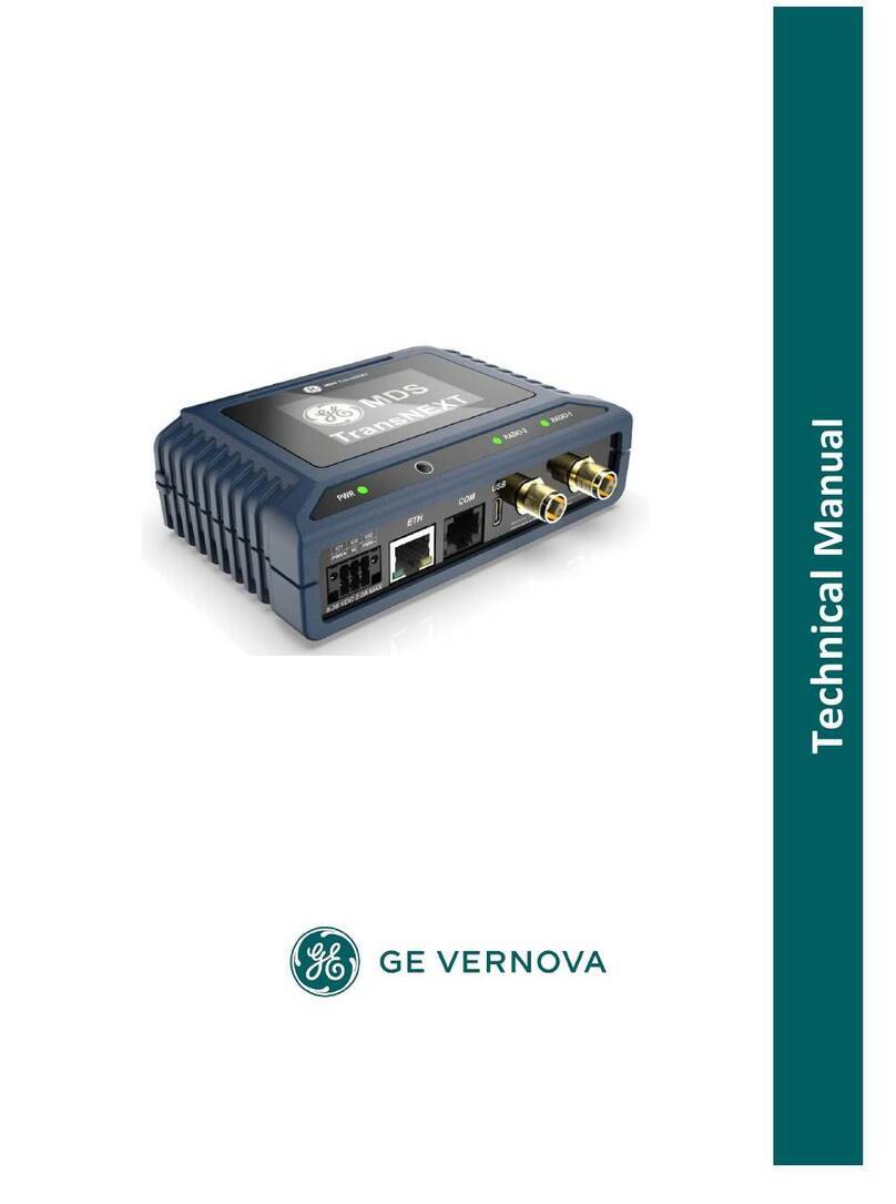
GE IC754PBSS01 Installation manual

QuickPanel* View
Communication Module
Hardware User’s Guide
PROFIBUS Slave Adapter
IC754PBSS01
April 2010
GFK-2291B

GFL-002
Warnings, Cautions, and Notes as Used in this Publication
Warning
Warning notices are used in this publication to emphasize that hazardous voltages,
currents, temperatures, or other conditions that could cause personal injury exist in
this equipment or may be associated with its use.
In situations where inattention could cause either personal injury or damage to
equipment, a Warning notice is used.
Caution
Caution notices are used where equipment might be damaged if care is not taken.
Note: Notes merely call attention to information that is especially significant to under-
standing and operating the equipment.
This document is based on information available at the time of its publication. While efforts
have been made to be accurate, the information contained herein does not purport to cover
all details or variations in hardware or software, nor to provide for every possible contingency
in connection with installation, operation, or maintenance. Features may be described herein
which are not present in all hardware and software systems. GE Intelligent Platforms as-
sumes no obligation of notice to holders of this document with respect to changes subse-
quently made.
GE Intelligent Platforms makes no representation or warranty, expressed, implied, or statu-
tory with respect to, and assumes no responsibility for the accuracy, completeness, suffi-
ciency, or usefulness of the information contained herein. No warranties of merchantability
or fitness for purpose shall apply.
* Indicates a trademark of GE Intelligent Platforms, Inc. and/or its affiliates. All other
trademarks are the property of their respective owners.
©Copyright 2010 GE Intelligent Platforms North America, Inc.
All Rights Reserved

Contact Information
If you purchased this product through an Authorized Channel Partner, please contact the
seller directly.
General Contact Information
Online technical support and Global Care http://www.ge-ip.com/support
Additional information http://www.ge-ip.com/
Technical Support
If you have technical problems that cannot be resolved with the information in this guide,
please contact us by telephone or email, or on the web at www.ge-ip.com/support
Americas
Online Technical Support www.ge-ip.com/support
Phone 1-800-433-2682
International Americas Direct Dial 1-780-420-2010 (if toll free 800 option is unavail-
able)
Customer Care Email customercare.ip@ge.com
Primary language of support English

Contact Information
Europe, the Middle East, and Africa
Online Technical Support www.ge-ip.com/support
Phone +800-1-433-2682
EMEA Direct Dial +352-26-722-780 (if toll free 800 option is unavail-
able or if dialing from a mobile telephone)
Primary languages of support English, French, German, Italian, Czech, Spanish
Asia Pacific
Online Technical Support www.ge-ip.com/support
Phone +86-400-820-8208
+86-21-3217-4826 (India, Indonesia, and Pakistan)

The PROFIBUS Slave has been tested and found to meet or exceed the requirements of
U.S. (47 CFR 15), Canadian (ICES-003), Australian (AS/NZS 3548) and European
(EN55011) regulations for Class A digital devices when installed in accordance with guide-
lines noted in this manual.
Note: This device complies with Part 15 of the FCC rules. Operation is subject to the
following two conditions: (1) This device may not cause harmful interference, and
(2) This device must accept any interference received that may cause undesired
operation.
Note: This equipment has been tested and found to comply with the limits for a Class A
digital device, pursuant to Part 15 of the FCC Rules. These limits are designed to
provide reasonable protection against harmful interference when the equipment
is operated in a commercial environment. This equipment generates, uses, and
can radiate radio frequency energy and, if not installed and used in accordance
with the instruction manual, may cause harmful interference to radio communica-
tions. Operation of this equipment in a residential area is likely to cause harmful
interference in which case the user will be required to correct the interference at
his own expense.
Note: This Class A digital apparatus complies with Canadian ICES-003.
The following statements are required to appear for Class 1, Div 2 Hazardous Locations.
1. EQUIPMENT LABELED WITH REFERENCE TO CLASS 1, GROUPS A, B, C, AND
D, DIV 2 HAZARDOUS LOCATIONS IS SUITABLE FOR USE IN CLASS 1, DIVISION
2, GROUPS A, B, C, D, OR NON-HAZARDOUS LOCATIONS ONLY.
2. WARNING - EXPLOSION HAZARD - SUBSTITUTION OF COMPONENTS MAY
IMPAIR SUITABILITY FOR CLASS 1, DIVISION 2.
3. WARNING - EXPLOSION HAZARD - DO NOT DISCONNECT EQUIPMENT
UNLESS POWER HAS BEEN SWITCHED OFF OR THE AREA IS KNOWN TO BE
NONHAZARDOUS.
The communication card meets ATEX Group II Category 3 when installed properly in a
QuickPanel View or Control OI.

Installation
PROFIBUS Slave Adapter GFK-2291B
6
Installing a Communication Module
Warning: Always use anti-static precautions when ac-
cessing the mating connector or the interior
of the unit.
1. Disconnect the DC input power terminal block connec-
tor from your QuickPanel View unit before connecting
the Communication Module to the unit.
Note: The 6” model QuickPanel is shown. Other models are similar.

Installation
GFK-2291B PROFIBUS Slave Adapter
7
2. Open the back cover.
3. Attach the Communication Module to the unit by plug-
ging the module into the mating connectors on the back
of the unit.
Caution: Be sure to properly align pins in the dual
connector upon insertion to avoid damage to the
card or the QuickPanel View unit.
4. Install the three screws to secure the card in the unit.
5. Close the cover.
Note: To use this card with QuickPanel View, CIMPLICITY Machine
Edition software is required. The Slave card is supported only in
QuickPanel View.

Features
PROFIBUS Slave Adapter GFK-2291B
8
Overview
The PROFIBUS module is shown below.

Features
GFK-2291B PROFIBUS Slave Adapter
9
PROFIBUS-DP Connector
9-Pin in D-sub
(female) Signal Description
1 NC -
2 - -
3 B-Line Positive RxD/TxD
4 RTS Request to send
5 GND Bus Isolated ground
6 +5V Bus Isolated +5V
7 - -
8 A-Line Negative RxD/TxD
9 - -
Case Shield -

Features
PROFIBUS Slave Adapter GFK-2291B
1
0
Node Address Switches
Before configuring the AnyBus-S PROFIBUS-DP module the node
address has to be set. This is done with two rotary switches on the
module, this enables address settings from 1-99 in decimal format.
Looking at the front of the module, the leftmost switch is used for
the ten setting and the rightmost switch is used for the setting of the
integers.
Example:
Address = (Left Switch Setting x 10) + (Right Switch Setting x 1)
Note: Another way of setting the node address is via the mailbox
telegram FB_SET_NODE_ADDRESS.
The node address range is then extended to 1-125.
See chapter that describes FB_SET_NODE_ADDRESS telegram.
Note: The node address cannot be changed during operation.

Features
GFK-2291B PROFIBUS Slave Adapter
11
LEDs
Four LEDs are located on the PROFIBUS Slave module. These
LEDs indicate the module status and the fieldbus status.
Not used
Off line
Ready (on line)
Diagnostics
LED no. Indication Description

Features
PROFIBUS Slave Adapter GFK-2291B
1
2
LED. Indication Description
Not used - Not Used
Ready Green Indicates that the module is On-Line on the fieldbus.
Green - Module is On-Line and data exchange is
possible.
Turned Off - Module is not On-Line
Off line Red Indicates that the module is Off-Line on the fieldbus.
Red - Module is Off-Line and no data exchange is
possible.
Turned Off - Module is not Off-Line

Features
GFK-2291B PROFIBUS Slave Adapter
1
3
LED. Indication Description
Diagnostics Red Fieldbus Diagnostics
Indicates certain faults on the Fieldbus side.
Flashing Red 1 Hz - Error in configuration: IN
and/or OUT length set during initialization of the
module is not equal to the length set during configu-
ration of the network.
Flashing Red 2 Hz - Error in User Parameter data:
The length/contents of the User Parameter data set
during initialization of the module is not equal to the
length/contents set during configuration of the net-
work.
Flashing Red 4 Hz - Error in initialization of the
PROFIBUS communication ASIC.
Turned Off - No diagnostics present

Specifications
PROFIBUS Slave Adapter GFK-2291B
14
Specifications
Network:
Protocol PROFIBUS Specification version: Vol. 1: 2.0,
Vol. 2: 2.0
Configuration test version: A-12
Data Rate All baud rates from 9600 bps to 12 Mbps with
auto baud rate detection
Termination Termination required at the end of the net-
work cable.
Environmental:
Storage Temperature -25° to 85°C
Operating Temperature 0° to 60°C
Operating Humidity 5 to 90% (non-condensing)
Table of contents
Other GE Conference System manuals