Prodys QLST User manual

Ocober 2017
Rev. 1.3
Last valid version: 2.2.2

Prodys S.L. Tel: +34 91 6896880 Fax: +34 91 6943777 Email: sales@prodys.net Web: www.prodys.com
Page 2
Index
Index 2
CE Declaration of Compliance 4
Introduction 5
I.1 QLST Features ....................................................................... 6
Installation Guide 7
II.1 Initial checks ........................................................................ 7
II.2 Setting the IP address.............................................................. 7
Front and Rear panels 9
III.1 Front Panel ......................................................................... 9
III.1.1 ON/OFF Button ................................................................ 9
III.1.2 USB Display connector ........................................................ 9
III.1.3 LEDs ............................................................................. 9
III.2 Rear Panels ........................................................................10
III.2.1 Power supply ..................................................................10
III.2.2 Audio interfaces ..............................................................10
III.2.2.1. Digital audio AES/EBU STEREO input/output 10
III.2.2.2. Analog audio input/output 11
III.2.3 Network interfaces...........................................................11
III.2.3.1. LAN1: 11
III.2.3.2. LAN2: 12
III.2.3.3. Wi-Fi on a USB modem: 13
III.2.4 Control interfaces ............................................................13
III.2.4.1. The RS232 port: 13
III.2.4.2. Rear USB slots: 14
III.3 Bottom side (Factory default switch)..........................................15
Technical Specifications 16
IV.1 Dimensions & Weight.............................................................16
IV.2 Power Supply ......................................................................16

Prodys S.L. Tel: +34 91 6896880 Fax: +34 91 6943777 Email: sales@prodys.net Web: www.prodys.com
Page 3
IV.3 User interface .....................................................................16
IV.4 Audio inputs /outputs & controls ..............................................16
IV.5 Communication ...................................................................16
IV.6 Audio Compression ...............................................................17
IV.7 Audio Storage .....................................................................17
Picture index 18

Prodys S.L. Tel: +34 91 6896880 Fax: +34 91 6943777 Email: sales@prodys.net Web: www.prodys.com
Page 4
CE Declaration of Compliance
Procesamiento Digital y Sistemas S.L., hereby declares that Quantum ST bearing
the CE168X parking are in compliance with Electromagnetic Compatibility
Directive (2004/108/EEC), and the Low Voltage Directive (2006/95/EEC) of the
European Union.
A “Declaration of conformity” for Quantum ST is available on file at Prodys offices
Your product is designed and manufactured with high quality
materials and components, which can be recycled and reused.
When this crossed-out wheeled bin symbol with black bar underneath
is attached to a product it means that product is covered by the
European Directive 2002/96/EC.
Please, inform yourself about the local separate collection system for
electrical and electronic products.
Please act according to your local rules and do not dispose of your old
products with your normal household waste. The correct disposal of
your old product will help prevent potential negative consequences for
the environment and human health.

Prodys S.L. Tel: +34 91 6896880 Fax: +34 91 6943777 Email: sales@prodys.net Web: www.prodys.com
Page 5
INTRODUCTION
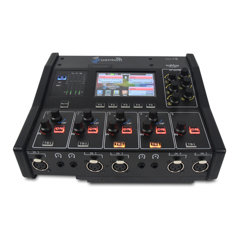
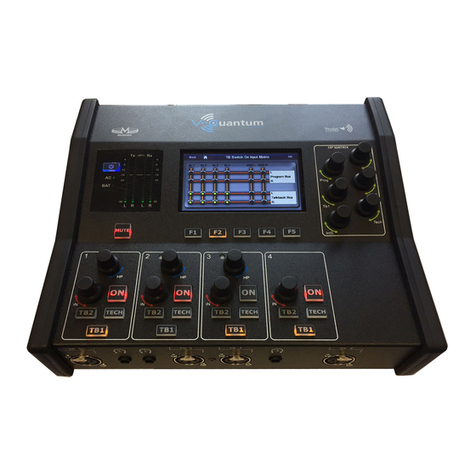
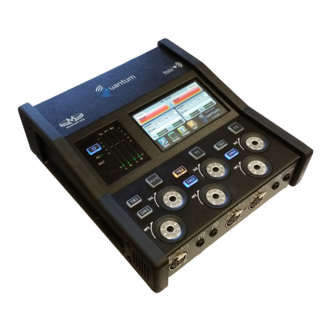
Picture 1. QLST codec.
QLST is a small IP audio codec designed to be the studio counterpart of the
Quantum Lite handheld audio codec. Like the rest of the audio codec from the
Quantum family, it inherits world-class IP technology from the Prodys Quantum
Codec Family.
Its main application is to receive, decode and store (in a external memory
device) audio streams from remote Quantum Lite units. But QLST is not just a
decoder; it is also capable of encoding audio back to the remote Quantum Lite
codec.
This unit can be controlled from its built-in web graphical interface, its front
panel display (optional), or from the ProdysControlPlus application.
Chapter I

Prodys S.L. Tel: +34 91 6896880 Fax: +34 91 6943777 Email: sales@prodys.net Web: www.prodys.com
Page 6
I.1 QLST Features
Among QLST most remarkable features are:
Analog Hardware or Digital Audio Hardware: Any of two flavours might
be purchased: either analogue or AES/EBU in/out. QLST is offered with
professional XLR line level audio inputs and outputs. These can be either
analog or AES/EBU digital.
Compression algorithms 1: QLST is equipped with OPUS and apt-X
compression algorithms to guarantee low delay communications.
Communications: IP (2 Ethernet interfaces).
Control and monitoring: This unit can be controlled from its built-in web
graphical interface, its front panel display menu (with an optional touch
panel), or from the ProdysControlPlus application. All the controls are
configurable remotely. It is also possible to remote control the unit from the
ProdysControlPlus application as long as the unit is connected to the Internet,
and even when the unit is connected to the Internet through a firewall.
1Other compression modes might be offered as option. Please contact us at sales@prodys.net
for further information in this regard.

Prodys S.L. Tel: +34 91 6896880 Fax: +34 91 6943777 Email: sales@prodys.net Web: www.prodys.com
Page 7
Installation Guide
This chapter describes the QLST hardware installation.
II.1 Initial checks
Before unpacking the unit, please check its packaging for any signs of damage or
mishandling during transportation. Report any damage to the shipping company
immediately. Unpack the unit carefully, if you find any damage or the unit does
not work correctly, you should contact Prodys or its distributor as soon as
possible.
II.2 Setting the IP address
QLST default IP configuration is DHCP, so if a codec is booted when connected
to a network with a DHCP server, this will assign a free IP address to the codec
in the established DHCP range.
When the user has a touch panel connected to the QLST, it’s very easy to find
out the IP address assigned by the DHCP server. It can be found in the “IP “ field
of Quantum Lite’s ‘Menu->Conf->Interfaces->Lan->IP’ menu:
Picture 2. QLST IP menu.
Chapter II

Prodys S.L. Tel: +34 91 6896880 Fax: +34 91 6943777 Email: sales@prodys.net Web: www.prodys.com
Page 8
Many times there is no visualization method available, so it’s important to follow
these steps to install the QLST:
1. Switch on the codec with the RJ45 cable directly connected between the
codec LAN1 connector and the computer.
2. Once the codec boots, without any DHCP server replying, it will set to the
default IP address 192.168.100.100
3. By means of your PC, IP address within the range 192.168.100.xxx,
connected to the LAN1 connector of the QLST and access its control
webpage with a browser at the address 192.168.100.100.
4. Change the codec IP address manually selecting “Use the following” in the
aforementioned menu.
Picture 3. Setting the local IP.

Prodys S.L. Tel: +34 91 6896880 Fax: +34 91 6943777 Email: sales@prodys.net Web: www.prodys.com
Page 9
FRONT AND REAR PANELS
III.1 Front Panel
Picture 4. QLST front panel.
III.1.1 ON/OFF Button
This button turns the power on /off.
III.1.2 USB Display connector
This connector allows the user to plug and unplug the touch panel (hot insertion
is allowed).
Take into account that the touch panel menu orientation can be rotated 180º. To
rotate the display, click on ‘Menu->Conf->System->Display->Rotate Display’.
III.1.3 LEDs
There are three LEDs in the front panel
ALARM: (Blinking red) An alarm event is taking place.
SYS: (Green) The codec is on and working.
PWR: (Blue) Power is on.
Chapter III

Prodys S.L. Tel: +34 91 6896880 Fax: +34 91 6943777 Email: sales@prodys.net Web: www.prodys.com
Page 10
III.2 Rear Panels
There are two different rear panel configuration depending on the kind of
input/ouputs: analog or digital:
Picture 5. QLST rear panel (digital)
Picture 6. QLST rear panel (analog)
III.2.1 Power supply
QLST comes supplied with an AC/DC converter (12 volts output) to be connected
to the power connector <VDC INPUT> located at the rear panel. The power
converter works with an AC input range of 100 to 240 VAC, 50 to 60 Hz.
III.2.2 Audio interfaces
III.2.2.1. Digital audio AES/EBU STEREO input/output
An AES/EBU interface is available via three XLR connectors on the rear panel of
the unit. The central connector provides the option to connect an externally
synchronised signal. The user can select via software if the digital output is to
synchronise with the audio input or with an external sync signal. The connectors
are wired in the following way:

Prodys S.L. Tel: +34 91 6896880 Fax: +34 91 6943777 Email: sales@prodys.net Web: www.prodys.com
Page 11
Pin
Function
1
Ground
2
AES/EBU IN-OUT-SYNC +
3
AES/EBU IN-OUT-SYNC -
III.2.2.2. Analog audio input/output
The analog audio I/O is connected through the XLR connections on the rear
panel. The wiring conforms to the following scheme:
Pin
Function
1
Ground
2
Audio+
3
Audio-
III.2.3 Network interfaces2
III.2.3.1. LAN1:
RJ-45 connector on the rear side; 10/100/1000BT Ethernet interface. Default
interface for streaming and remote control.
This interface is always enabled and it is used for transmission and reception of
control data (Web and ProdysControlPlus), regardless of the settings for the
Streaming Network option (be it Wi-Fi, Ethernet, Custom…).
When ‘Custom’ is selected as the streaming network configuration menu, LAN1
can be selected as IP interface for bonding to other IP interfaces and thus to
2If the QLST is always initiating the AoIP calls to another QLST (for example), you might benefit
from the bonding option adding the streaming bandwidth of LAN1 and LAN2 at the <NET =
CUSTOM> setting (BRAVE protocol). Please notice using this bonding configuration, this QLST
is not able to get anymore an incoming call from its mate; it is just set to be always the calling
party.

Prodys S.L. Tel: +34 91 6896880 Fax: +34 91 6943777 Email: sales@prodys.net Web: www.prodys.com
Page 12
transmit and receive audio data. In this case, LAN1 will carry both audio and
control data simultaneously.
When LAN2 interface is disabled and ‘Ethernet’ is selected as the streaming
network configuration menu, LAN1 will transmit and receive all audio.
But, when LAN2 is enabled, and ‘Ethernet’ is selected as the streaming network
configuration menu, LAN1 interface will only transmit control data (web control,
ProdysControlPlus or any other IP data not related to the audio streaming.
III.2.3.2. LAN2:
RJ-45 connector on the rear side; 10/100/1000BT Ethernet interface. It can be
enabled or disabled by the user.
This interface will carry the streaming data (not control) if the LAN2 interface is
enabled in the configuration. When enabled it is available for bonding or diversity
with other IP interfaces to stream audio data.
LAN LED’s:
In the socket there are two leds to indicate different states for the connection
and these are very useful in problem-solving situations.
Green LED LINK STATUS: ON = Connected
Orange LED RECEIVE STATUS: On = Receiving Data.
From the web interface and the touch panel menu it is possible to set the speed
and duplex configuration to the following values: AUTO, 10HD, 10FD, 100HD,
100FD. Click on ‘Menu->Conf->Interfaces->LAN->Ethernet’.

Prodys S.L. Tel: +34 91 6896880 Fax: +34 91 6943777 Email: sales@prodys.net Web: www.prodys.com
Page 13
Picture 7: Ethernet Menu
III.2.3.3. Wi-Fi on a USB modem:
A USB Wi-Fi modem can be supplied optionally with the unit. This Wi-Fi
connection can be used for streaming or for bonding to other IP interfaces to
stream audio and video data.
Wi-Fi standards: 802.11b, 802.11g, 802.11n
Security protocols: 128-bit WEP, 64-bit WEP, WPA, WPA2.
III.2.4 Control interfaces
III.2.4.1. The RS232 port:
This port is meant to be used as an auxiliary data port. This port allows the
transmission and reception of data along with encoded audio. Note that this
socket is RJ45 connector, as opposed to the typical Sub-D 9 ways connector. To
make the conversion between RJ45 and RS232 Sub-D connector there are
modular connectors available that should be wired as follows:

Prodys S.L. Tel: +34 91 6896880 Fax: +34 91 6943777 Email: sales@prodys.net Web: www.prodys.com
Page 14
RJ45
Connector
9-pin female
D-sub
Connector
1 (NC)
1
2 (Rx)
3
3 (GND)
5
4 (NC)
4
5 (NC)
6
6 (GND)
7
7 (Tx)
2
8 (NC)
8
1,4,5,8 must be unconnected
The port is always set to 8 DATA bits, NO parity, 1 START bit and 1 STOP bit.
The bit rate can be adjusted to between 300 and 9600 bps via software.
Each QLST acts as a DCE device, therefore the connection to each of the
RS232 ports is wired in the following way:
QLST –Pin 7 connector RJ45.........................Pin 2 PC
QLST –Pin 2 connector RJ45.........................Pin 3 PC
QLST –Pin 3,6 connector RJ45.......................Pin 5 PC
Hardware handshaking signals are ignored.
III.2.4.2. Rear USB slots:
Two USB slots (Host 2.0) are available on the rear side for the connection of
memory storage devices or for future applications.
External storage should be formatted as FAT323. Maximum addressed storage
capacity is 2 TB.
3NTFS format is not supported

Prodys S.L. Tel: +34 91 6896880 Fax: +34 91 6943777 Email: sales@prodys.net Web: www.prodys.com
Page 15
III.3 Bottom side (Factory default switch)
At the bottom side, a small open gap, allows access to an octal microswitch.
By default all the switches must be in OFF position according the picture.
Switch number 7 will restore the default factory configuration if
set ON before a power cycle.
The IP address is changed to a DHCP IP configuration. In case a
DHCP server is not available on the network the address is set to
192.168.100.100 and the net mask to 255.255.255.0.
After the factory default setting the switch number 7 must return to the OFF
position for usual operation.
ON
OFF

Prodys S.L. Tel: +34 91 6896880 Fax: +34 91 6943777 Email: sales@prodys.net Web: www.prodys.com
Page 16
TECHNICAL SPECIFICATIONS
IV.1 Dimensions & Weight
Width: 210mm; Height: 42 mm; Depth: 173 mm.
Weight: 500 g.
IV.2 Power Supply
1x VDC input 90V to 264V
Connector plug Ø5.5 x Ø2.5 x 11mm.
IV.3 User interface
1x capacitive touch panel 95 x 55mm (optional).
1x remote web control.
Front power on/off.
LED status indication for alarm and power-on.
IV.4 Audio inputs /outputs
Analog or digital stereo inputs/outputs with XLR connectors.
IV.5 Communication
1x Control Ethernet port (10/100/1000BaseTx Ethernet, RJ45 connector).
1x Streaming Ethernet port (10/100/1000BaseTx Ethernet, RJ45
connector).
2x USB ports (Host 2.0 with maximum 500mA current supply)
1x RS232. RJ45 connector.
BRAVE protocol with bonding or diversity.
Capítulo IV

Prodys S.L. Tel: +34 91 6896880 Fax: +34 91 6943777 Email: sales@prodys.net Web: www.prodys.com
Page 17
IV.6 Audio Compression4
Enhanced aptXTM.
OPUS
IV.7 Audio Storage
Audio recording on external USB memory device.
Recording time depending on memory size:
WAV Format –1 track, 48K Sample Rate at 16 Bit Depth
1GB: 3hrs, 7 mins
2GB: 6hrs, 13 mins
4GB: 12hrs, 26 mins
8GB: 24hrs, 52 mins
16GB: 49hrs, 44 mins
32GB: 99hrs, 29 mins
64GB: 198hrs, 57 mins
132GB: 410hrs, 21 mins
264GB: 820hrs, 42 mins
4Some compression modes might be available as an option. Please contact sales@prodys.net
for more information.

Prodys S.L. Tel: +34 91 6896880 Fax: +34 91 6943777 Email: sales@prodys.net Web: www.prodys.com
Page 18
PICTURE INDEX
Picture 1. QLST codec. ....................................................................................5
Picture 2. QLST IP menu. ................................................................................7
Picture 3. Setting the local IP. .........................................................................8
Picture 4. QLST front panel. ............................................................................9
Picture 5. QLST rear panel (digital) ................................................................ 10
Picture 6. QLST rear panel (analog) ............................................................... 10
Picture 7: Ethernet Menu .............................................................................. 13
Table of contents
Other Prodys Conference System manuals
