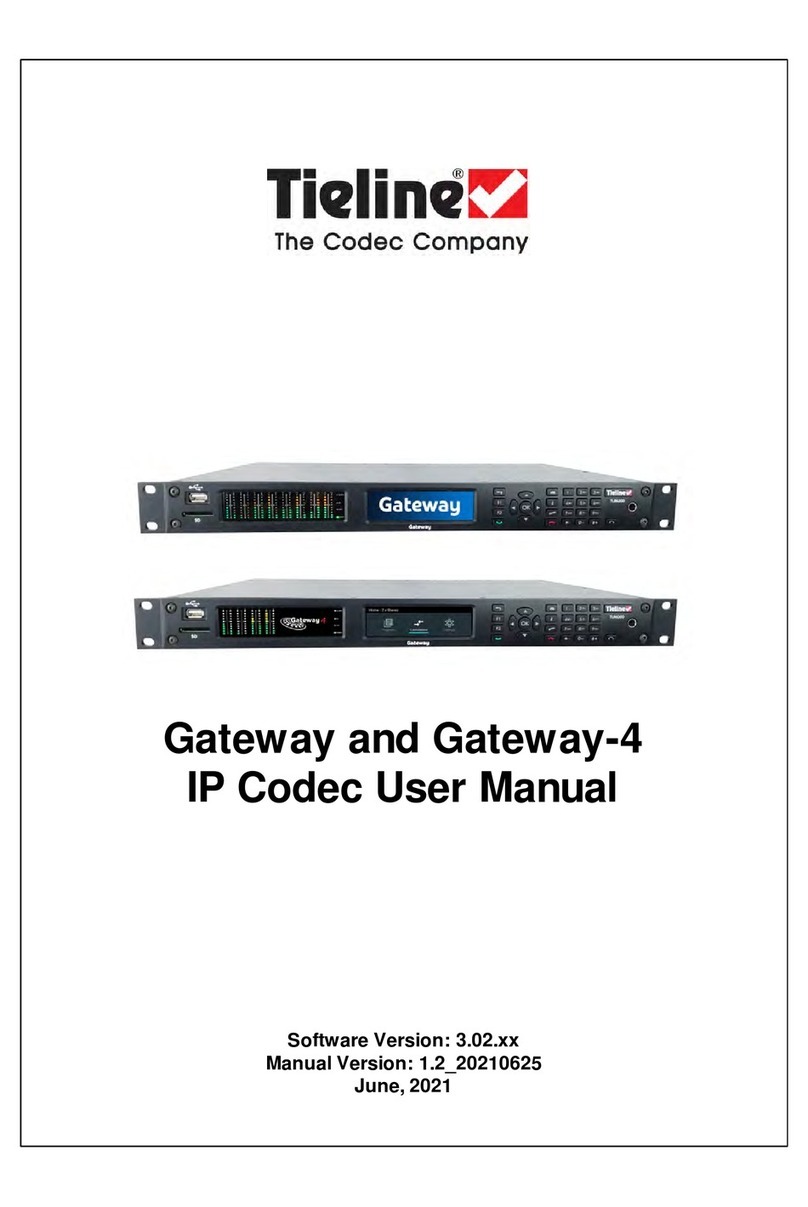
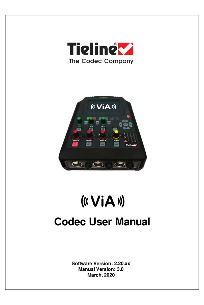
Codec Tieline ViA Manual

Quick Start User Manual
Software Version: 2.20.xx
Manual Version: 3.0
March, 2020
Visit www.tieline.com/Support/Documentation/User-Manuals to
download the latest user manual.

2
© Tieline Research Pty. Ltd. 2020
ViA User Manual v3
Table of Contents
Part I Warnings & Safety Information 3
Part II Battery Use and Power
Management 8
Part III Inserting and Removing Modules 10
Part IV Wireless IP Connection Options 10
................................................................................................................................... 171 Cellular Activation in the USA
Part V Connection Guide 17
................................................................................................................................... 191 Connecting over IP
................................................................................................................................... 232 Advanced IP Connection Settings
................................................................................................................................... 273 Connecting over SIP
................................................................................................................................... 324 Connecting with ISDN
................................................................................................................................... 355 Connecting POTS
Part VI ViA Headphone Controls 38

3
© Tieline Research Pty. Ltd. 2020
ViA User Manual v3
1 Warnings & Safety Information
1. The power cable and battery must be removed fromthe device for Power Disconnection.
2. Remove phone or ISDNcables fromthe codec before removing a module or servicing.
THUNDERSTORM ANDLIGHTNING WARNING:
DO NOT USETieline codecs during thunderstorms and lightning. You may suffer an injury using a phone, Tieline
codec, or any device connected to a phone during a thunderstorm. This can lead to personal injury and in
extreme cases may be fatal. Protective devices can be fitted to the line, however, due to the extremely high
voltages and energy levels involved in lightning strikes, these devices may not offer protection to the users, or
the Tieline codec and equipment connected to the codec.
Secondary strikes can occur. These secondary strikes are induced by lightning strikes and also produce
dangerously high currents and energy levels. You only need to be near an object struck by lightning to lead to
personalinjury or damage to equipment. e.g. if you are located near a lighting tower at a sports facility, water
features and drains on golf courses, you may be affected by these secondary strikes.
Damage to personneland Tieline codecs may occur during thunderstorm, even if the codec is turned off but
remains connected to the phone or ISDNsystem, LANor the power.
ANY DAMAGETO A TIELINEPRODUCT CAUSEDBY LIGHTNING or an ELECTRICAL STORMWILL VOID THE
WARRANTY.
DIGITAL PHONESYSTEM WARNING:
DO NOT CONNECT THEANALOG POTS MODULETO A DIGITAL PHONESYSTEM. PERMANENT DAMAGEMAY
OCCUR!If you are unfamiliar with any facility, check that the line you are using is NOTa digital line. If the Tieline
codec becomes faulty due to the use of a digital phone system, the WARRANTY WILL BEVOID.
SAFETY PRECAUTION:
·Any procedures that involve opening panels or changing components must be performed by qualified service
personnel only.
SERVICING WARNINGS:
·Do not performany servicing other than that contained in the operating instructions unless you are qualified
to do so.
·Allw ork should be carried out by suitably qualified personnel.
LINEVOLTAGE:
·Before connecting the ACadapter to the power line, make sure the voltage of the power source
matches the requirements of the device. Refer to the device Specifications for information about the
correct power rating for the unit.
WARNING: To Reduce the Risk of Electrical Shock and Fire
1. All servicing must be undertaken only by qualified service personnel. There are not user serviceable parts
inside the unit.
2. DO NOTplug in, turn on or attempt to operate an obviously damaged unit.
3. Ensure that the chassis ventilation slots/holes in the unit are NOTCOVEREDORBLOCKED.
4. Do not operate the device in a location where the maximumambient temperature exceeds 40°C(104°F), or
is below 0°C(32°F).

4 ViA User Manual v3
© Tieline Research Pty. Ltd. 2020
LITHIUM-ION BATTERY WARNINGS:
1. Please read the RRC2057 battery user manualshipped with this product before use. It includes very
important safety, charging, operational and disposal information. This user manual can also be dow nloaded
at http://www.rrc-ps.com/.
2. For safety reasons, the battery is prevented fromdischarging (i.e. frompowering the codec) if the internal
temperature reaches a pre-set threshold. If a battery temperature warning is displayed, the battery should
be removed fromthe codec and allowed to cool.
3. For safety reasons, the battery is prevented fromcharging if the internal temperature reaches a pre-set
threshold. Move the codec to a cooler location to allow the battery to continue charging.
4. If a battery is installed and the “battery unavailable” icon appears (or the battery icon doesn’t appear at all).
The battery should immediately be removed fromthe codec. Please contact Tieline if this situation persists.
5. The battery may continue to charge when external power is applied to the codec even when the codec is
off.
6. When external power is not being applied to the codec, the battery will discharge slow ly even if the codec
is off. To avoid depleting the battery it should be removed fromthe codec when not in use.
BATTERY TRANSPORTATION
1. This device includes a Lithium-ion battery and it is the owner’s responsibility to ship this device in full
compliance w ith all of the latest applicable transportation regulations. For air transport, refer to current
IATA and FAA regulations, as appropriate, and to your carrier for air transport compliance information. For
worldwide sea transportation compliance information refer to the IMO-IMDG code (special provision 188).
For European road transportation compliance information see ADR(special provision 188).
2. When the codec is first shipped fromTieline to the customer the battery pack is delivered in shipping-mode
(status display off, no measurable voltage at the connector).
3. Please request the RRC2057 Material Safety Data Sheet fromRRCat http://www.rrc-ps.com/ for additional
transportation and regulatory information.
GENERAL WARNINGS:
1. Do not operate the codec on a hot surface.
2. Only operate the codec within the specified environmental conditions. The codec is considered to be in an
operational state when external power is being supplied or the battery is installed, even if the codec is off.
3. If the environmental conditions exceed the specified values, the codec should be switched off, external
power should be removed and the battery should be removed fromthe codec.
4. Do not operate or store the codec in direct sunlight for an extended period of time. Heat build-up due to
sunlight exposure can cause permanent damage to the codec that is not covered under w arranty.
RADIO FREQUENCY SAFETY INFORMATION:
IMPORTANT: To satisfy radio frequency exposure compliance requirements, the antenna and transmitter in the
ViA codec, or cellular module antennas/transmitters, must be at least 20 cm from all persons and must not be
used in conjunction with any other antennas or transmitters. Only use the product with the supplied antenna/s.
Failure to adhere this may result in the product exceeding RF exposure limits and may void the user’s
authorization to operate the equipment.
The device has an internal Wi-Fi antenna which is located at the rear of the unit. For optimumperformance with
minimumpower consumption do not shield the device or cover w ith any object. Covering the antenna affects
signal quality, may cause the product to operate at a higher power level than needed, and may shorten battery
life.
Due to the possibility of radio frequency (RF) interference, it is important that you follow any special regulations
regarding the use of radio equipment. Follow the safety advice:
·Operating your device close to other electronic equipment may cause interference if the equipment is
inadequately protected. Observe any warning signs and manufacturers’ recommendations.
·Different industries and businesses restrict the use of cellular devices. Respect restrictions on the use
of radio equipment in fuel depots, chemical plants, or w here blasting operations are in process. Follow
restrictions for any environment where you operate the device.
·Do not place the antenna outdoors.
·Switch OFF your wireless device w hen in an aircraft. Using portable electronic devices in an aircraft
may endanger aircraft operation, disrupt the cellular network, and is illegal. Failing to observe this
restriction
may lead to suspension or denial of cellular services to the offender, legalaction, or both.
·Switch OFF your wireless device when around gasoline or diesel-fuel pumps and before filling your
vehicle with fuel.

5
© Tieline Research Pty. Ltd. 2020
ViA User Manual v3
·Switch OFFyour wireless device in hospitals and any other place where medical equipment may be in
use.
Sécurité relative aux appareils à radiofréquence (RF)
À cause du risque d'interférences de radiofréquence (RF), il est important de respecter toutes les
réglementations spéciales relatives aux équipements radio. Suivez les conseils de sécurité ci-dessous.
·Utiliser l'appareil à proximité d'autres équipements électroniques peut causer des interférences si les
équipements ne sont pas bien protégés. Respectez tous les panneaux d'avertissement et les
recommandations du fabricant.
·Certains secteurs industriels et certaines entreprises limitent l'utilisation des appareils cellulaires.
Respectez ces restrictions relatives aux équipements radio dans les dépôts de carburant, dans les
usines de produits
chimiques, ou dans les zones où des dynamitages sont en cours. Suivez les restrictions relatives à
chaque type d'environnement où vous utiliserez l'appareil.
·Ne placez pas l'antenne en extérieur.
·Éteignez votre appareilsans fil dans les avions. L'utilisation d'appareils électroniques portables en avion
est illégale: elle peut fortement perturber le fonctionnement de l'appareil et désactiver le réseau cellulaire.
S'il
ne respecte pas cette consigne, le responsable peut voir son accès aux services cellulaires suspendu ou
interdit, peut être poursuivi en justice, ou les deux.
·Éteignez votre appareil sans fil à proximité des pompes à essence ou de diesel avant de remplir le
réservoir de votre véhicule de carburant.
·Éteignez votre appareil sans fil dans les hôpitaux ou dans toutes les zones où des appareils médicaux
sont susceptibles d'être utilisés.
Interference with Pacemakers and Other Medical Devices
Potential interference:
Radio frequency energy (RF) from cellular devices can interact with some electronic devices. This is
electromagnetic interference (EMI). The FDA helped develop a detailed test method to measure EMI of implanted
cardiac pacemakers and defibrillators fromcellular devices. This test method is part of the Association for the
Advancement of Medical Instrumentation (AAMI) standard. This standard allows manufacturers to ensure that
cardiac pacemakers and defibrillators are safe from cellular device EMI. The FDA continues to monitor cellular
devices for interactions with other medical devices. If harmful interference occurs, the FDA will assess the
interference and work to resolve the problem.
Precautions for pacemaker wearers:
If EMIoccurs, it could affect a pacemaker in one of three ways:
·Stop the pacemaker fromdelivering the stimulating pulses that regulate the heart's rhythm.
·Cause the pacemaker to deliver the pulses irregularly.
·Cause the pacemaker to ignore the heart's own rhythmand deliver pulses at a fixed rate.
Based on current research, cellular devices do not pose a significant health problem for most pacemaker
wearers. However, people w ith pacemakers may want to take simple precautions to be sure that their device
doesn't cause a problem.
·Keep the device on the opposite side of the body fromthe pacemaker to add extra distance between the
pacemaker and the device.
·Avoid placing a turned-on device next to the pacemaker (for example, don’t carry the device in a shirt or
jacket pocket directly over the pacemaker).
Vehicle Safety
When using your device in a vehicle:
·Do not use this device while driving.
·Respect national regulations on the use of cellular devices in vehicles.
·If incorrectly installed in a vehicle, operating the wireless device could interfere with the vehicle’s
electronics. To avoid such problems, use qualified personnel to install the device. The installer should
verify the vehicle electronics are protected frominterference.
·Using an alert device to operate a vehicle’s lights or horn is not permitted on public roads.
·UL evaluated this device for use in ordinary locations only. UL did NOT evaluate this device for
installation in a vehicle or other outdoor locations. UL Certification does not apply or extend to use
vehicles or outdoor applications or in ambient temperatures above 40° C.
Device Maintenance
When maintaining your device:

6 ViA User Manual v3
© Tieline Research Pty. Ltd. 2020
·Do not attempt to disassemble the device. There are no user serviceable parts inside.
·Do not expose your device to any extreme environment where the temperature or humidity is high.
·Do not expose the device to water, rain, or spilled beverages. It is not waterproof.
·Do not place the device alongside computer discs, credit or travel cards, or other magnetic media. The
information contained on discs or cards may be affected by the device.
·Using accessories, such as antennas, that Tieline has not authorized or that are not compliant with
Tieline's accessory specifications may invalidate the warranty.
SAFELISTENING GUIDANCE
WARNING: LISTENING TO AUDIO AT EXCESSIVEVOLUMES CAN CAUSEPERMANENT HEARING DAMAGE.
USEAS LOW A VOLUMEAS POSSIBLE.
Over exposure to excessive sound levels can damage your ears resulting in permanent noise-induced hearing
loss (NIHL). Please use applicable health and safety authority guidelines on maximumexposure limits. As a rule
of thumb, avoid extended periods listening to sound pressure levels (SPLs) of 85dBA or higher.
CHINESESAFETY WARNINGS:
This device must only be used in not-tropicalclimate regions.
This device must only be used at altitude not exceeding 2000 meters.
JAPANESESAFETY WARNINGS:
Statement for Class A VCCI-certified Equipment:
Translation of previous Class A VCCIStatement: This is a Class A product based on the standard of the
Voluntary Control Council for Interference by Information Technology Equipment (VCCI). If this equipment is used
in a domestic environment, radio disturbance may occur, in which case, the user may be required to take
corrective action.
Special Notices for North American Users:
For North American power connection, select a power supply cord that is UL Listed and CSA Certified 3 -
conductor, [18 AWG], terminated in a molded on plug cap rated 125 V, [5 A], with a minimumlength of 1.5m[six
feet] but no longer than 4.5m.
Special Notices for European Users:
For European connection, select a power supply cord that is internationally harmonized and marked “<HAR>”, 3
- conductor, 0,75 mm2 minimummm2 wire, rated 300 V, with a PVCinsulated jacket. The cord must have a
molded on plug cap rated 250 V, 3 A.
Interconnection Cabling:
Cables for connecting to the unit's RS232 and Ethernet Interfaces must be UL certified type DP-1 or DP-2. (Note:
when residing in non-LPS circuit)
Overcurrent Protection:
A readily accessible listed branch-circuit over current protective device rated 15 A must be incorporated in the
building wiring for the power input.
Replaceable Batteries:
The equipment is provided with replaceable batteries, and if replaced by an incorrect battery type, then an
explosion may occur.

7
© Tieline Research Pty. Ltd. 2020
ViA User Manual v3
CAUTION: RISKOF EXPLOSION IF BATTERY IS REPLACEDBY AN INCORRECT BATTERY TYPE. DISPOSE
OF USED BATTERIES ACCORDING TO THEINSTRUCTIONS.
This equipment is provided with a long life replaceable Panasonic CR2032 model 3V manganese dioxide lithium
coin battery. Service personnel should only replace this battery with the same brand and type of battery. If this
is replaced by an incorrect battery type, then an explosion may occur. Contact the manufacturer to view the
Material Safety Data Sheet for this battery.
This equipment is provided with a replaceable RRC2057 Lithium-ion battery. Service personnelshould only
replace this battery with the same brand and type of battery. If this is replaced by an incorrect battery type, then
an explosion may occur. Contact the manufacturer to view the Material Safety Data Sheet for this battery.
End of Life Statement
Tieline hereby declares that all materials, components and products supplied are in full compliance w ith RoHS & WEE
directives. This product must be disposed of according to local laws and regulations. Because the product contains a
battery it must be disposed of separately fromhousehold waste. Do not incinerate, but take it to a recycling facility.
Warranty and Disclaimer
This equipment manufactured by Tieline is warranted by Tieline against defects in material and workmanship for two
years from the date of original purchase. During the w arranty period, we will repair or, at our option, replace at no
charge a product that proves to be defective, provided you obtain return authorization from Tieline and return the
product, shipping prepaid, to Tieline. For return authorization, contact Tieline's US or Australian office (see
www.tieline.com).
This Warranty does not apply if the product has been damaged by accident or misuse or as the result of service or
modification performed by anyone other than Tieline. With the exception of the warranties set forth above, Tieline
makes no other warranties, expressed or implied or statutory, including but not limited to warranties of merchantability
and fitness for a particular purpose, which are hereby expressly disclaimed. Use of this product is subject to Tieline's
SOFTWARE LICENSE and WARRANTY conditions, which should be viewed at www.tieline.com before using this
product.
In no event will Tieline, its directors, officers, employees, agents, owners, consultants or advisers (its “Affiliates”), or
authorized dealers or their respective Affiliates, be liable for incidental or consequential damages, or for loss, damage,
or expense directly or indirectly arising fromthe use of any Product or the inability to use any Product either separately
or in combination with other equipment or materials, or fromany other cause.
Whilst every effort has been made to ensure the accuracy of this manual we are not responsible for any errors or
omissions within it. The product specifications and descriptions w ithin this manual will be subject to improvements and
modifications over time without notice, as changes to software and hardware are implemented. This codec can
provide high voltages on inputs and suitable broadcast equipment must be used at all times. Tieline takes no
responsibility for any damage to equipment attached to the codec.
Battery Warranty
Tieline expressly disclaims any and all implied warranties on the RRC Li-ion Smart Battery Pack RRC2057. The
manufacturer's warranty applies. Contact the battery manufacturer for any warranty claims. To contact the battery
manufacturer visit their website at http://www.rrc-ps.com/.

8 ViA User Manual v3
© Tieline Research Pty. Ltd. 2020
2 Battery Use and Power Management
ViA has an internal battery slot on the rear panel designed for high performance RRC2057 Lithium-
ion smart batteries. Only use this battery in the codec.
Caution:
1. Please read the important safety and user information in the manufacturer user manuals
for both the battery and any external charger purchased separately before use.
2. The internal BATTERY is delivered in shipping-mode (status display off, no measurable
voltage at the connector). Attach the codec power supply to the POWER SOCKET to
charge the battery. When you start the charge cycle the BATTERY will be activated.
Charge fully before first use.
3. If the codec is off the BATTERY continues to charge when external power is applied to
the codec.
Inserting the Battery
1. Push down on the BATTERY CASE CLIP to open the lid to the battery compartment.
2. Insert the BATTERY carefully and ensure the grooves at the bottom of the BATTERY line up
correctly with the bottom of the BATTERY COMPARTMENT. Note: It should slide in smoothly.
3. Replace the BATTERY CASE CLIP carefully by lining up the two protruding plastic lugs with the
base of the compartment, then push the center of the BATTERY CASE CLIP to close it fully.
Removing the Battery
1. Push down on the BATTERY CASE CLIP to open the lid for the BATTERY COMPARTMENT.
2. Pinch the tag on the BATTERY to pull it slowly out of the BATTERY COMPARTMENT.
Charging the Battery
When the power supply is connected to the codec's POWER SOCKET it will charge the internal
BATTERY in less than 4 hrs.
Battery Indications
The battery has a charge status button to verify its charge state when it is [ON]. The POWER
button is green when the power supply is connected to the codec's power socket. When the codec
is operating on battery power it provides the following battery level indications:
1. The Battery symbol and charge remaining is visible in the Status Bar in the top right corner
of the TOUCH SCREEN.
2. When operating on battery power the POWER button indications are as follows:
LED Indication
Battery State
GREEN LED (Solid)
Battery level is between 21 - 100 %
ORANGE LED (Solid)
Battery level is between 11 - 20 %
RED LED (Solid)
Battery level is between 6 - 10 %
RED LED (Flashing)
Battery level is 5% or lower
Low Battery Headphone Alarm Tones
A low battery alarm is audible in the headphones when the battery level reaches 20%, 10% and 5%.
1. Alarm tones are audible in the left headphone output of HP 1-3.

9
© Tieline Research Pty. Ltd. 2020
ViA User Manual v3
2. A warning dialog is displayed on the TOUCH SCREEN until acknowledged.
3. The ALARM LED flashes until acknowledged, and then turns solid red.
Tap the TOUCH SCREEN or touch any codec controls to acknowledge the alarm and stop the alarm
tones.
Touch Screen Battery Indications
The percentage of battery charge remaining is displayed next to the battery symbol in the Status
Bar on the TOUCH SCREEN. In addition:
·When power is attached to the codec the BATTERY symbol is green and the white Power
symbol is displayed.
·When operating on battery power the BATTERY symbol is white.
Symbol
Battery State
Power is attached to the codec and the battery is charging.
The battery is fully charged and no power is attached to the codec.
The battery is fully charged and the external power supply is in use.
Unknown battery error while the external power supply is attached. The battery
should immediately be removed from the codec. Please contact Tieline if this
situation persists.
Unknown battery error. The battery should immediately be removed from the
codec. Please contact Tieline if this situation persists.
The battery is too hot or too cold. Move the codec to a cooler or warmer
location as required.
The battery has overheated or is faulty. For safety reasons the battery will be
prevented from discharging and powering the codec. Plug in external power to
prevent imminent shutdown. The battery MUST be removed from the codec and
allowed to cool.
An external power supply is attached and the battery is too hot or too cold and
not charging. For safety reasons, the battery is prevented from charging if the
internal temperature is above or below pre-set thresholds. Move the codec to a
cooler or warmer location as required, to allow the battery to continue charging.
An external power supply is attached and the battery has overheated or is
faulty. For safety reasons the battery is prevented from charging, or
discharging and powering the codec. The battery MUST be removed from the
codec and allowed to cool.
HTML5 Toolbox Web-GUI Low Battery Indications
A low battery icon is displayed in the HTML5 Toolbox Web-GUI when the battery level is 20 percent
or lower. This flashes until it is acknowledged on the unit itself.

10 ViA User Manual v3
© Tieline Research Pty. Ltd. 2020
3 Inserting and Removing Modules
A single module slot is available on the codec rear panel for inserting an optional cellular, ISDN or
POTS module into the codec.
ViA codec with an ISDN module installed
Inserting or Removing a Module
Ensure the codec is [OFF] when inserting or removing modules. Where possible use anti-
static precautions to help minimize the chance of static charges damaging the highly
sensitive circuitry. Do not force a module into the codec. Modules should be installed
slowly and gently.
1. Press the POWER button and tap Shut Down to turn the codec [OFF].
2. Remove the 4 screws from the blanking panel or module installed in the codec.
3. Carefully slide the new module into the module slot and ensure the base of the module remains
flat during insertion, to ensure it lines up correctly with the module connector in the codec.
4. Reinsert the 4 screws to hold the module firmly in place.
5. Press the POWER button to power up the codec.
6. Press the HOME button to return to the Home screen and tap Settings .
7. Tap Transport Interfaces to expand the menu and tap ISDN Module, POTS Module or
Cellular > Cellular Module to configure module settings.
4 Wireless IP Connection Options
The codec has multiple IP interface connection options, including:
1. LAN1 Ethernet port (default Primary Via interface)
2. LAN2 Ethernet port (default Secondary Via interface)
3. Internal Wi-Fi (default Tertiary Via interface)
4. External USB PORT 1. Note: for use with a USB modem or tethered smartphone.
5. External USB PORT 2. Note: for use with a USB modem or tethered smartphone.
6. Optional Internal Single SIM LTE Module. Note: two antennas are shipped with this module to
support diversity.
7. Optional Internal Dual Active SIM LTE Module: Note: Requires firmware v2.20.xx or higher and
four antennas are shipped with this module to support diversity.
For more information about prioritizing the interface used when dialing a connection see Configuring
Via Interfaces.
Connecting a Wi-Fi Access Point
To connect the codec to a Wi-Fi network access point:
1. Press the HOME button to return to the Home screen, then tap Settings .

11
© Tieline Research Pty. Ltd. 2020
ViA User Manual v3
2. Tap to select Transport Interfaces and then tap Wi-Fi .
3. Ensure the Wi-Fi State is Enabled and tap Rescan Access Points if the required Wi-Fi
network is not populated in the access point list.
4. Tap to select the Wi-Fi access point to which you are connecting, in this example
AndroidAP.
5. Tap to select the preferred Authentication Mode and then tap Password to enter the
network password.

12 ViA User Manual v3
© Tieline Research Pty. Ltd. 2020
6. Enter the password, then tap Done in the top right-hand corner of the TOUCH SCREEN.
7. Tap Connect in the top right-hand corner of the TOUCH SCREEN to connect to the Wi-Fi
network.
8. Verify the Wi-Fi symbol is visible in the Status Bar to confirm the codec has connected
to the Wi-Fi access point.
Important Note: ViA supports IEEE 802.11 a/b/g/n Wi-Fi with dual band connectivity (2.4
and 5 GHz). For increased security Tieline has implemented the WPA2-PSK
authentication protocol because standard WEP encryption is less secure.
Wi-Fi Indications
The following Wi-Fi indications are displayed in the Status Bar on the codec screen.
Symbol
Description of Status
1
No symbol
displayed
Wi-Fi is disabled in the codec

13
© Tieline Research Pty. Ltd. 2020
ViA User Manual v3
2
·Wi-Fi is enabled in the codec, but it is out of range of a Wi-Fi network, or
·The codec is within range of a Wi-Fi network, but is either not connected
or is in the process of connecting
3
The codec is connected to a Wi-Fi network and signal strength is displayed
Browser Wi-Fi Login
Some Wi-Fi networks require a browser to log in and connect to the access point, e.g. hotel Wi-Fi
networks. To log in to this type of network:
1. Press the HOME button to return to the Home screen, then tap Settings >
Transport Interfaces > Wi-Fi .
2. Tap to select the network to which you are connecting.
3. Tap to select Portal Browser to launch a web-browser on the TOUCH SCREEN. Then enter
credentials and/or accept terms as required in the web-browser.
Helpful Hint: Use fingers on the TOUCH SCREEN to pinch zoom in to web-browser
content, or zoom out.
Connecting over Cellular Wireless via USB Modems
1. Attach a supported USB Modem to either USB PORT 1 or USB PORT 2 on the codec. When
the modem is detected by the codec, the network symbol and signal strength is displayed in the
Status Bar on the TOUCH SCREEN. Note: It may take up to 90 seconds for the modem to be
detected by the codec and connect to the network.

14 ViA User Manual v3
© Tieline Research Pty. Ltd. 2020
2. From the Home screen tap Settings > Transport Interfaces > Cellular > USB1/2
Modem to view menus and cellular modem details.
Important Notes:
·Sometimes a cellular network will be detected and a USB modem will connect
automatically after it is inserted. Tieline recommends always using the Overwrite APN
(Access Point Number) menu setting and entering the correct APN for your Telco. This
ensures use of the correct data APN. It is usually simple to search the internet for the
correct APNs used by each Telco. See Adding Access Points and a SIM PIN for more
details.
·It may be necessary to enter a SIM PIN if the codec cannot connect automatically to
the network.
·To safely remove a USB modem press the HOME button to return to the Home
screen, then tap Settings > System > Safe Eject .
USB Cellular ModemIndications
Symbol
Description of Status
1
No symbol
·A cellular modem is not attached to the codec.
·A modem is attached but not ready yet; it can take up to a minute for
the modem to be detected.
·The modem has a SIM card issue (locked or not present).
·The modem is not supported by the codec.
2
Each USB port is identified by the number 1 or 2 in the top-left corner of
the symbol.
3
A cellular modem is attached to the codec but there is an error. Check
that:·The SIM card does not have a PIN code enabled.
·The modem has data enabled.
·The modem is compatible with the network to which you are
attempting to connect.
4
The cellular modem is connected to the network and signal strength is
displayed. Note: when first attached the symbol is greyed out while the
modem is connecting to the cellular network. It will remain greyed out if:
·Data is not enabled.
·No APN is selected and the modem doesn't contain a correct APN
setting from a factory default or previous connection.
·An incorrect APN is selected. When using different SIMs they may
require different APNs, even if they are from the same Telco.
·The correct APN is selected but data has run out.
·A custom APN has been added but either the APN info, or the
Authentication Type, is incorrect.

15
© Tieline Research Pty. Ltd. 2020
ViA User Manual v3
Connecting using a Cellular Module
1. Turn the codec off and insert a cellular module into the module slot.
2. Power up the codec and press the HOME button to return to the Home screen, then tap
Settings > Transport Interfaces > Cellular > Cellular Module 1 / 2 to view cellular
module menus and details.
Important Notes:
·Sometimes a cellular network will be detected and a module will connect automatically
after it is inserted. Tieline recommends always using the Overwrite APN (Access
Point Number) menu setting and entering the correct APN for your Telco. This ensures
use of the correct data APN. It is usually simple to search the internet for the correct
APNs used by each Telco. See Adding Access Points and a SIM PIN for more details.
·It may be necessary to enter a SIM PIN if the codec cannot connect automatically to
the network.
·Cellular radio transmissions can be turned off without removing the module. Select
Settings > Transport Interfaces > Cellular > Cellular Module 1 / 2 >
Enable Radio [OFF]
SIM LTE Indications
Indications displayed in the Status Bar on the TOUCH SCREEN for an internal cellular module
are similar to USB modem cellular network indications. The only difference is that S1 and S2 is
displayed to identify SIM card 1 and 2. In the following image there are two USB modems and
two SIM cards displayed in the Status Bar.
Tethering a Smartphone
Important Note: Only tethering to an Android phone is supported.
It is possible to tether a phone to the codec with a USB cable and use cellular or Wi-Fi data from
the connected device.
1. Enable USB tethering in the smartphone to allow sharing of the phone's internet connection.
Note: This will probably need to be enabled each time the phone is connected to the codec.
2. Attach a USB cable to the phone and then attach the USB cable to one of the two host USB
PORTs on the codec.

16 ViA User Manual v3
© Tieline Research Pty. Ltd. 2020
3. The codec should detect the smartphone connection and acquire an IP address from the
phone. When it connects successfully the USB tethering symbol changes from greyed
out to illuminated in the Status Bar at the top of the TOUCH SCREEN.
4. Select Any, or choose USB1 or USB2 when specifying a Via interface to use when
connecting.
Wi-Fi Hotspot Configuration
The codec supports Wi-Fi hotspot data sharing, which allows external devices to share data.
1. Press the HOME button to return to the Home screen, then tap Settings >
Transport Interfaces > Wi-Fi > State.
2. Tap Hotspot to enable the Wi-Fi hotspot.
3. Tap Hotspot Settings to adjust Wi-Fi hotspot settings.
4. Tap Password to edit the default Wi-Fi hotspot password.

17
© Tieline Research Pty. Ltd. 2020
ViA User Manual v3
5. Tap Parent Interface to choose the interface from which data will be shared using the Wi-Fi
hotspot.
6. When a device connects successfully the Hotspot symbol changes from greyed out to
illuminated in the Status Bar in the top right corner of the TOUCH SCREEN.
Helpful Hint: Note the Wi-Fi IP address on the screen when you set up a hotspot and
then enter this IP address in a browser on a device connected to the hotspot, e.g. a
tablet, to view the Toolbox HTML web-GUI for the codec and control the codec.
Important Note: Exercise extreme caution when using the Wi-Fi hotspot feature if
streaming live IP audio simultaneously while this mode is enabled. Sharing data may lead
to less reliable IP connections due to reduced bandwidth being available.
4.1 Cellular Activation in the USA
LTE Activation Notice
Before using a Tieline ViA LTE module in the USA it is necessary to set up a wireless account with
your Telco. Follow the steps in the tech note at the following link to set up a wireless account:
https://www.multitech.com/documents/publications/activation-guides/lte-device-activation-steps-
s000620.pdf
5 Connection Guide
This quick start guide will get you connected with ViA in mono or stereo in just a few minutes.
Configuration features on the Connections screen are as follows:

18 ViA User Manual v3
© Tieline Research Pty. Ltd. 2020
Feature
Description
1
Audio Stream name /
button
Displays the audio stream name; tap to edit audio stream
settings, including Stream Name, Caller ID, Routing Type, G3
Profile Type, G3 Channel.
2
Connect button
Tap the Connect button to dial a connection.
3
Connection type /
TieLink selector
Tap to toggle between selecting whether to dial a configured
IP/SIP, ISDN or POTS connection, or a TieLink Address Book
contact.
4
Dialing destination
Tap to enter an IP/SIP address or ISDN/POTS number, or select a
TieLink Contact list contact if TieLink is configured.
5
Destination settings
Tap to configure destination settings, e.g. dialing interface and IP
ports.
6
Add SmartStream PLUS
Tap the Plus symbol to add a SmartStream PLUS dialing
connection. By default, the last configured IP address is inserted
in a new SmartStream PLUS connection.
7
Connection settings
Tap to adjust connection-related settings like Transport,
Algorithm, Auto Reconnect, Jitter Buffer, FEC, Direction, Auxiliary
Data, Connection Name.
8
Information (statistics)
Tap to view audio stream connection statistics, e.g. Link quality,
packet statistics. Swipe in this screen to view other active audio
stream statistics.
9
Expand / Collapse
Tap to expand or collapse the audio stream information displayed.
10
PPMs
Audio stream PPMs for send and return audio in dBFS by default.
11
'Hamburger Menu'
Tap to load a default or custom program, or create a new program
and save it as a custom program. Switch between Basic and
Admin modes of operation.
12
Program name
The name of the loaded program.
The codec is configured to connect in mono over IP by default when shipped, or when factory default
settings are restored.
1. Ensure the codec is not powered up when inserting or removing modules.
2. Attach the 12VDC power supply to the codec or insert the charged BATTERY. Note: the
BATTERY is automatically charged inside the codec when the power supply is connected.
3. Attach headphones and microphones to the codec.
4. Press the POWER button to power up the codec.

19
© Tieline Research Pty. Ltd. 2020
ViA User Manual v3
5. Press the INPUT ON/OFF button to turn each input on and adjust the INPUT GAIN rotary
encoder for each microphone. Note: Navigate to Home screen > Audio > Inputs >
Input Type > Gain Type to adjust coarse gain levels for each input source.
6. Follow the procedure for connecting over IP, SIP, ISDN or POTS.
CAUTION: DO NOT attach non-digital microphones or an AES3 source to input 1 when
AES42 mode is selected, or equipment may be damaged by high voltages.
Important Note:
·Unused inputs should be turned [OFF] to avoid introducing noise and improve audio
quality.
·To load a saved program and dial, press the HOME button to return to the Home
screen and then tap Programs . Tap to select the program you want to use and
then tap Load Program in the dialog. Tap Connect or press the CONNECT button
to dial using the newly loaded program.
·It is also possible to load a program from the Connections screen. From the Home
screen tap Connections > Menu > Load Program [tap to select a custom
program], or tap Default Program and select a program from the default
configurations listed.
Helpful Hints:
·Swipe left once from the home screen to view programs selected as Favorites. To learn
more about configuring programs as Favorites see Load, Connect and Manage
Programs.
·The codec remembers recent calls just like a cell-phone. To view Call History press the
CONNECT button in any screen, except when you have selected Programs from
the Home screen.
·If you don't rename and save a program during configuration, the default program is
displayed in the Call History list if you want to redial the program.
5.1 Connecting over IP
The following procedure will use a default 'program' to connect using the codec's TOUCH SCREEN.
For IP connections, attach an RJ45 Ethernet cable to one of the LAN ports on the codec's left side
panel, or use one of the codec's wireless IP connection options.
The following example uses Tieline default settings to create a stereo IP connection:
1. Press the HOME button to return to the Home screen, then tap Connections .

20 ViA User Manual v3
© Tieline Research Pty. Ltd. 2020
2. Tap Menu and then tap Default Programs to view default program options. Note: Tap
Load Program to load preconfigured custom programs. Default programs cannot be locked
in the codec. Save a program as a custom program if a program needs to be locked.
3. Tap to select the preferred program connection option, e.g. Default Mono or Default
Stereo, and then tap Done in the top right-hand corner of the TOUCH SCREEN.
4. With factory default settings the codec is configured to connect over IP. To adjust
connection settings tap the Connection Settings symbol.
5. If required, tap Transport and select IP > Tieline Codecs if ISDN or POTS is the currently
configured transport. Note: Select SIP instead of Tieline Codecs when dialing non-Tieline
codecs. Select Sessionless to dial a sessionless IP connection over networks supporting
this connection method.
Other manuals for Tieline ViA
1
Table of contents
Other Codec Conference System manuals
Popular Conference System manuals by other brands

Grandstream Networks
Grandstream Networks RingCentral GRP260X Configuration guide

Power Dynamics
Power Dynamics TG40T instruction manual

LEGRAND
LEGRAND Tynetec Advent XT2 installation manual

Hubbell
Hubbell GAI-TRONICS ICS/SP2 Page/Party manual

Siemens
Siemens HiPath 3000 V3.0 or later Gigaset M1... user manual

MSA
MSA ClearCommand HCS Operation and maintenance instructions