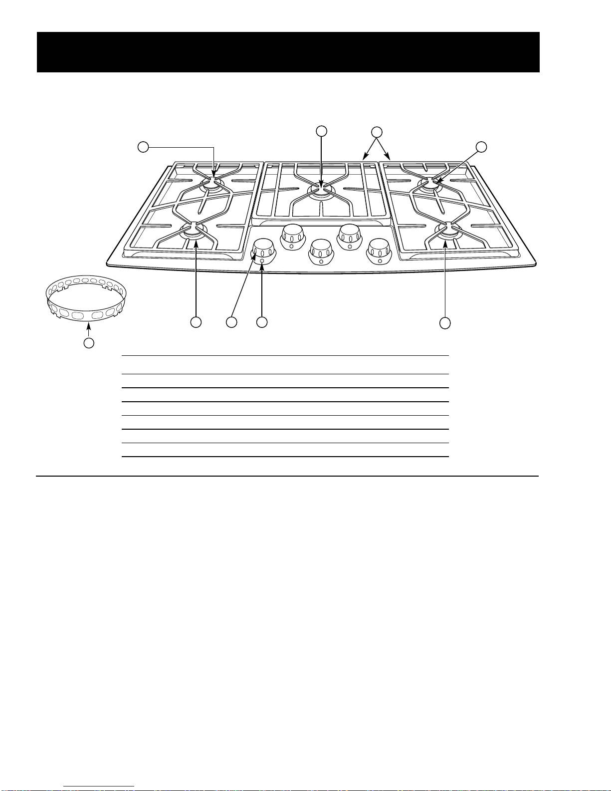
GE Monogram ZGU375NS How to use

g
g
PUB # 31-9088 12/01
MODEL SERIES:
TECHNICALSERVICE GUIDE
GE Consumer Home Services Training
36-In. Monogram
Stainless Steel Gas Cooktop
ZGU375NS
ZGU375LS

IMPORTANT SAFETY NOTICE
The information in this service guide is intended for use by
individuals possessing adequate backgrounds of electrical,
electronic, and mechanical experience. Any attempt to repair a
major appliance may result in personal injury and property
damage. The manufacturer or seller cannot be responsible for the
interpretation of this information, nor can it assume any liability in
connection with its use.
WARNING
Iftheinformationinthismanualisnotfollowedexactly,afireorexplo-
sion may result causing property damage, personal injury or death.
If you smell gas:
- Do not try to light any appliance.
- Do not touch any electrical switch; do not use any phone in
thebuilding.
- Immediately call the gas supplier from a neighbor’s phone.
Follow the gas supplier’s instructions.
- If you cannot reach the gas supplier, call the fire department.
WARNING
Toavoidpersonalinjury,disconnectpowerbefore servicing this prod-
uct. If electrical power is required for diagnosis or test
purposes, disconnect the power immediately after performing the
necessary checks.
RECONNECT ALL GROUNDING DEVICES
If grounding wires, screws, straps, clips, nuts, or washers used to
complete a path to ground are removed for service, they must
be returned to their original position and properly fastened.
GE Consumer Home Services Training
Technical Service Guide
Copyright © 2001
All rights reserved. This service guide may not be reproduced in whole or in
part in any form without written permission from the General Electric Company.
!

– 1 –
Table of Contents
Table of Contents
Introduction . . . . . . . . . . . . . . . . . . . . . . . . . . . . . . . . . . . . . . . . . . . . . . . . . . . . . 2
Installation . . . . . . . . . . . . . . . . . . . . . . . . . . . . . . . . . . . . . . . . . . . . . . . . . . . . . . 3
Specifications and Nomenclature5 . . . . . . . . . . . . . . . . . . . . . . . . . . . . . . . . . . 4
Warranty Information. . . . . . . . . . . . . . . . . . . . . . . . . . . . . . . . . . . . . . . . . . . . . . 5
Cooktop Features and Controls . . . . . . . . . . . . . . . . . . . . . . . . . . . . . . . . . . . . 6
Mechanical Disassembly . . . . . . . . . . . . . . . . . . . . . . . . . . . . . . . . . . . . . . . . . 10
Troubleshooting . . . . . . . . . . . . . . . . . . . . . . . . . . . . . . . . . . . . . . . . . . . . . . . . 16
Component and Connector Locator Views . . . . . . . . . . . . . . . . . . . . . . . . . . 18
Wiring Diagram . . . . . . . . . . . . . . . . . . . . . . . . . . . . . . . . . . . . . . . . . . . . . . . . . 20
Schematics . . . . . . . . . . . . . . . . . . . . . . . . . . . . . . . . . . . . . . . . . . . . . . . . . . . . 21
Parts List . . . . . . . . . . . . . . . . . . . . . . . . . . . . . . . . . . . . . . . . . . . . . . . . . . . . . . 22
Conversion to/from LP (Propane) Gas . . . . . . . . . . . . . . . . . . . . . . . . . . . . . . 26
[[Title]]

– 2 –
Introduction
The new Monogram cooktop makes an eloquent
statement of style, convenience, and kitchen
planning flexibility. Whether chosen for its purity of
design, assiduous attention to detail—or for both of
these reasons—you’ll find that the Monogram
cooktop’s superior blend of form and function will
be a delight for years to come.
This Monogram cooktop was designed to provide
the flexibility to blend in with any kitchen cabinetry.
Its sleek design can be beautifully integrated into
the kitchen.
The information on the following pages will help
you service this Monogram cooktop efficiently and
effectively.

–3 –
Installation
WARNING: Before beginning the installation,
switch power off at the service panel and lock the
service disconnecting means. When the service
disconnecting means cannot be locked, securely
fasten a warning tag to the service panel.
Before You Begin...
Note: The complete installation instructions
are inclosed with the
Use and Care Manual
.
Carefully read and follow these instructions.
Gas Supply
WARNING: Cooktop model ZGU375NS isshipped
from the factory set to operate only with natural
gas. Do not use with LPG. If you wish to use
LPG, you must have cooktop model ZGU375LS.
These cooktops are designed to operate on natural
gas at 4 in. of water column pressure or on LP gas
at 10 in. of water column pressure, depending on
model. For proper operation, the maximum inlet
pressure to the regulator must be no more than
10 in. of water column pressure for natural gas
and 14 in. of water column pressure for LP gas.
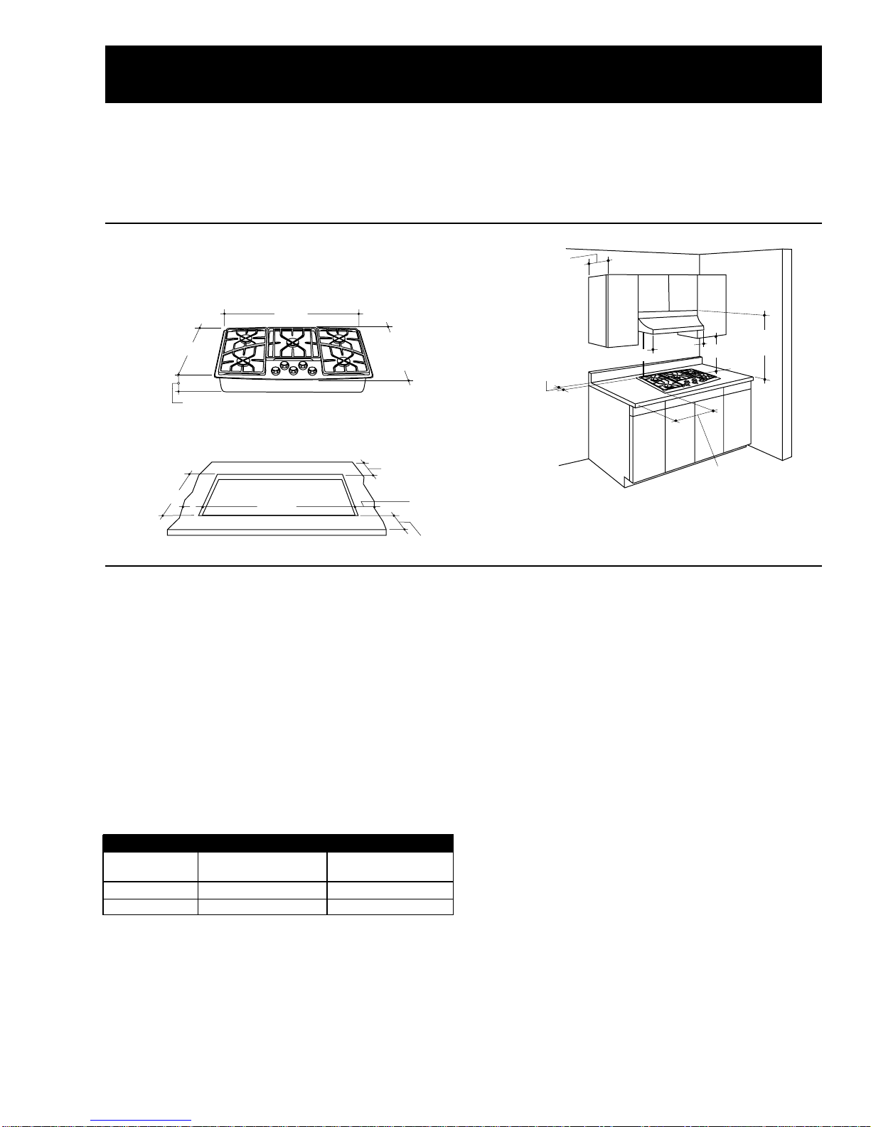
20-5/8"
Deep
at Center
19-3/4"
36-1/2"
5-1/2"
18-7/8"
3-3/8" Min. From Cutout
to Vertica Combustib es
2-3/4" Min.
35-5/16" 7-9/16" Min. to
Wa From Cutout
2-3/
4
From
to V
e
Com
b
Surf
a
Insta
Monogram Cooktop Dimensions
Dimensionsforreferenceonly
Unitshown fully assembled
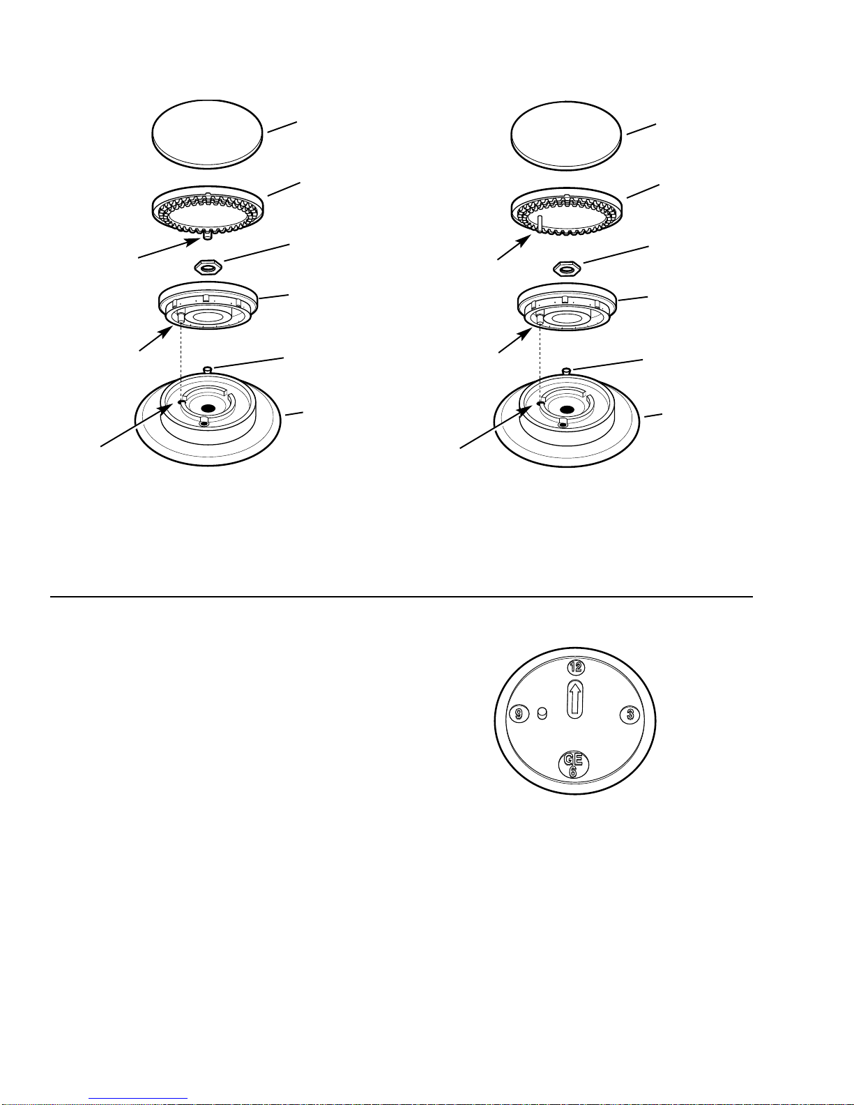
Gas Supply Shutoff Valve
The cooktop itself is not equipped with a gas shut-
off valve. If installed correctly, a shutoff valve will be
in the main gas supply line “upstream”of the
appliance pressure regulator.
Measuring the Gas Pressure
Supplied to the Burners
A pressure tap hole is located on the side of the
regulator to allow checking of the manifold pres-
sure. Remove the regulator plug and install a
WB02X10820 tap (or 1/8 in. NPT nipple) for test
with a manometer. Turn on the gas and light at least
one burner to serve as a load. Reinstall the regular
plug and check for leaks.
Optional Combination Installations
This cooktop may be installed in combination with a
ZVB36 Monogram downdraft vent, with a ZTD30
warming drawer, or with a ZET837 single convec-
tion oven. The gas and electrical supply must be
located where it will not interfere with the vent
housing, the oven, or the warming drawer.
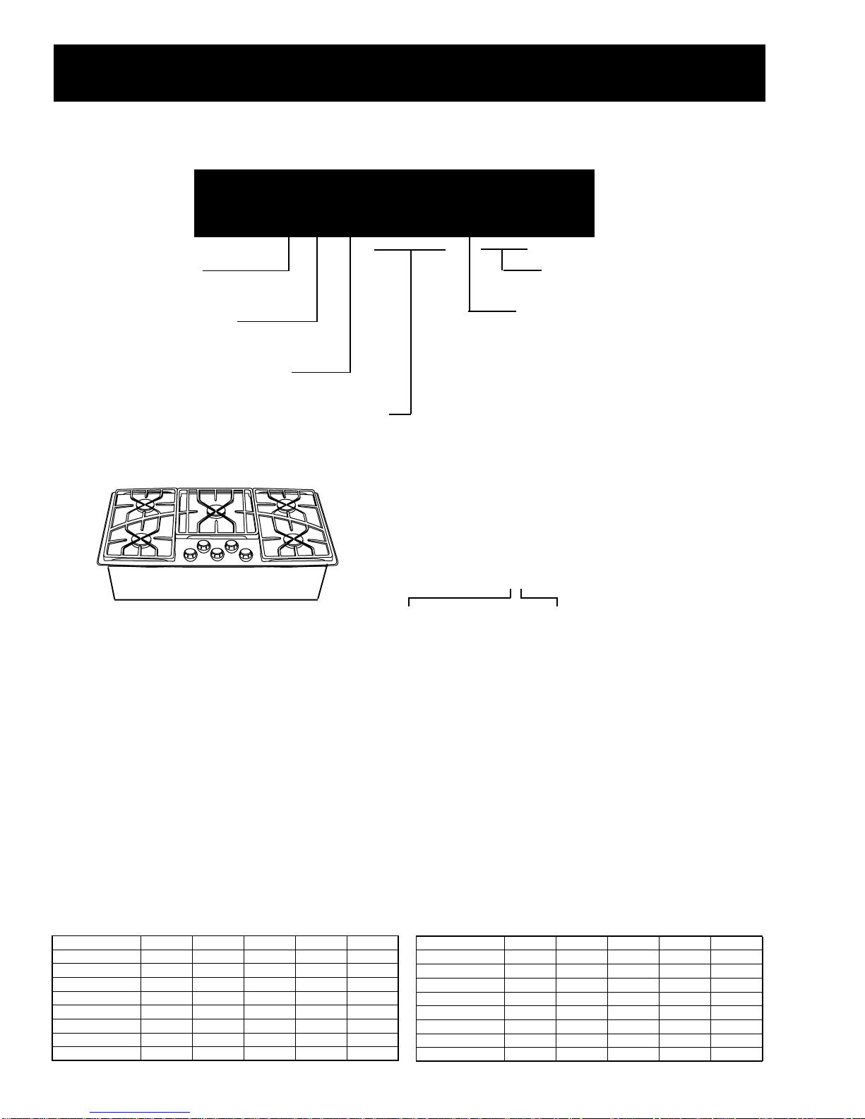
GAS SUPPLY REQUIREMENTS
Gas Type Incoming Pressure Pressure Regulator
to Regulator Output Supplies
Natural 6.0" to 9.0" W.C.P. 4.0" W.C.P.
LP 11" to 14" W.C.P. 10.0" W.C.P.
Recommended minimum regulator input pressure
to maximize performance:
Natural Gas –7.0-in. W.C.P.
LP Gas –12.0-in. W.C.P.
Cutout
stib es
n. to
utout
18" Min.
13"
Max.
36" Min.
2-3/4" Min.
From Cooktop
to Vertica
Combustib e
Surface When
Insta ed
7" Min. to Wa
From Cooktop Edge
When Insta ed Both Sides
30"
Min.
See Note
Note: Refer to hood installation instructions for dimension.

–4 –
Specifications and Nomenclature
Model Number
Serial Number
The first two characters of the serial number
identify the month and year of manufacture.
Example: AA123456S=January,2001
A-JAN 2005 - H
D - FEB 2004 - G
F - MAR 2003 - F
G -APR 2002 - D
H- MAY 2001 - A
L- JUN 2000 - Z
M-JUL 1999 - V
R -AUG 1998 - T
S - SEP 1997 - S
T - OCT 1996 - R
V - NOV 1995 - M
Z - DEC 1994 - L
Note: The technical sheet is located under the
control panel.
The letter designating the
year repeats every 12
years.
Example:
T - 1974
T - 1986
T - 1998
Z G U 3 7 5 N S
Monogram
GAS
Cooktop
Feature Pack
Designates features–the higher
the number, the more features.
Stainless Steel
Type of Gas to Be Used
N = Natural
L = LPG
The serial plate of your cooktop is located on
the bottom of the burner box. In addition to
the model and serial numbers, it tells you the
ratings of the burners and the type of fuel
and pressure the cooktop was adjusted for
when it left the factory. Also included are
minimum wall clearance requirements.
LP Gas
Orifice/Jet DMS
Natural Gas
LP @ 10" LF LR RR RF C
Rate, HI 8.5K 8.5K 8.5K 8.5K 15K
Rate,LOW 2.3K 2.3K 2.3K 2.3K 2.4K
Rate,SIM 1.1K 1.1K 1.1K 1.1K 1.1K
Main Orifice 0.81 mm 0.81 mm 0.81 mm 0.81 mm 1.10 mm
Sim. Orifice 0.34 mm 0.34 mm 0.34 mm 0.34 mm 0.37 mm
V
alve Jet 0.46 mm 0.46 mm 0.46 mm 0.46 mm 0.46 mm
Main Or. C l
r
White White White White Black
Sim. Or. C de EEEEG
Natural @ 4" LF LR RR RF C
Rate, HI 10.5K 12K 12K 10.5K 15K
Rate,LOW 2.5K 2.5K 2.5K 2.5K 3.4K
Rate,SIM 1.2K 1.2K 1.2K 1.2K 1.2K
Main Orifice 1.45mm 1.59 mm 1.59 mm 1.45mm 1.78 mm
Sim. Orifice 0.57 mm 0.57 mm 0.57 mm 0.57 mm 0.51 mm
Valve Jet 0.71 mm 0.71 mm 0.71 mm 0.71 mm 0.71 mm
Main Or. C l
r
Orange Re Re Orange Yellow
Sim. Or. C de PPPPV

–5 –
Warranty Information
Warrantor: General Electric Company, Louisville, KY 40225
Sales slip or cancelled check is required as proof of original purchase date to
obtain service under warranty.
All warranty service is provided by our Factory Service Centers or an authorized
Customer Care
®
technician.
What is
Covered
What is
Not
Covered
FULL ONE-YEAR WARRANTY
For one year from date of original purchase, we will provide, free of charge, parts and
service labor in your home to repair or replace any part of the cooktop that fails because
of a manufacturing defect.
This warranty is extended to the original purchaser and any succeeding owner for products
purchased for ordinary home use in the 48 mainland states, Hawaii and Washington, D.C.
In Alaska the warranty is the same except that it is LIMITED because you must pay to ship
the product to the service shop or for the service technician’s travel costs to your home.
All warranty service will be provided by our Factory Service Centers or by our authorized
Customer Care® servicers during normal working hours.
Should your appliance need service, during warranty period or beyond, call 800-444-1845.
Some states do not allow the exclusion or limitation of incidental or consequential damages,
so the above limitation or exclusion may not apply to you. This warranty gives you specific legal
rights, and you may also have other rights which vary from state to state.
To know what your legal rights are in your state, consult your local or state consumer affairs
office or your state’s Attorney General.
•Service trips to your home to teach you how
to use the product.
•Replacement of house fuses or resetting of
circuit breakers.
•Damage to the product caused by accident,
fire, floods or acts of God.
•Failure of the product if it is used for other
than its intended purpose or used
commercially.
•Improper installation.
If you have an installation problem, contact
your dealer or installer. You are responsible
for providing adequate electrical, gas,
exhausting and other connecting facilities
as described in the Installation Instructions
provided with the product.
WARRANTOR IS NOT RESPONSIBLE
FOR CONSEQUENTIAL DAMAGES.

–6 –
Cooktop Features and Controls
Throughout this manual, features and appearances may vary from the customer’s model.
Ignition System
The surface burners are lit by electronic ignition,
eliminating the need for standing pilot lights with
constantly burning flames.
The ignition system consists of 5 spark switches
(1 on each valve), 5 spark electrodes (1 on each
burner), and a spark module.
WARNING: All 5 electrodes will spark when any
burner control knob is turned on. Do NOT
touch any of the burners when the igniters
are clicking.
The burners relight automatically if the flame goes
out. The burner control knob can be turned to any
position from HIGH to LO to light the burner. The
sparking will quit after the burner has been lit.
The burners may spark if a draft blows the flame
away from the burner sensor.
The ignition system is not sensitive to reversed
house wiring polarity.
Lighting a Burner
Push the control knob down and turn it counter-
clockwise to the desired position from HIGH to
SIM.
In case of a power outage, you can light the burn-
ers with a match. Hold a lit match to the burner,
then push in and turn the control knob to the de-
sired position. Use extreme caution when light-
ing burners this way.
Surface burners in use when an electrical power
failure occurs will continue to operate normally.
Feature Index
1Dual-Flame Spillproof Burners—High Output
2 Dual-Flame Spillproof Burner—Maximum Output
3Tactile-touch Control Knobs (One for Each Surface Burner)
4Burner “ON”Indicator Lamps (One on Each Control Knob)
5Interlocking Grates
6Wok Ring Accessory
Design
information
(Not all features
are on all models.
Appearance may vary.)
1
5
1 43
1 1
2
6
6

–7 –
Burner Cleaning
The slits in the burner rings of the cooktop must
be kept clean at all times for an even, unhampered
flame.
The electrode of
the spark igniter is
behind each burner.
When one burner is
turned to “ON”to
light, all the burners
spark. Do not attempt to disassemble or clean
around any burner while another burner is
on. An electric shock may result, which could
cause you to knock over hot cookware.
Electrode
Note: Before removing the burner caps and
burner ring subassemblies, remember their size
and location. Replace them in the same location
after cleaning for proper burner operation.
High
Output
High
Output
High
Output
High
Output
Front of Cooktop
Maximum
Output
To completely clean the burner ring subassembly
remove the burner cap, head, and the 1-1/16 in.
nut. Lift off the burner ring. Do not remove the
burner bases.
Make sure the small holes in the simmer rings are
kept open. A sewing needle or wire twist-tie works
well to unclog them.
Ho es
S its
To remove burned-on food, soak the burner heads
Check to be sure the burner you turned on is
the one you want to use.
After the burner lights, turn the knob in
eitherdirection to adjust the flame size. To turn a
burner off, turn the knob clockwise as far as it will
go, to the OFF position.
The indicator lamp in the bezel for each knob
verifies the burner is ON.
Caution: Do not operate a burner for an extended
period of time without cookware on the grate. The
finish on the grate may chip without cookware to
absorb the heat.
Selecting Flame Size
All 5 burners on your cooktop have 2 rows of
flames. These dual-flame burners have an upper
ring of main burner ports which produce the main
flame for high-heat cooking from the HI knob
setting to the LO knob setting.
Main F ame
Simmer F ame
The bottom simmer flame is used for simmer
heat cooking operations such as melting choco-
late, holding food at serving temperature, and
simmering.
Both MAIN and SIMMER flames are lit when the
knob is between HI and LO. Only the simmer
flame is lit when the knob is in the SIMMER
position.
BurnerAdjustment
There is no adjustment on this burner. See
Burner Cleaning.

–8 –
and rings in a solution of mild liquid detergent and
hot water for 20-30 minutes. For more stubborn
stains, use a toothbrush. Clean the burner
bases in place on the cooktop.
Before putting the burner parts back, shake out
excess water and then dry them thoroughly by
setting them in a warm oven for 30 minutes.
Replace the burner parts. Make sure that the rings,
heads, and caps are replaced in the correct
location. There are four medium sets and one
large set of rings, heads, and caps.
To replace the burner parts, make sure all parts
are for the correct burner, in the correct location,
and firmly seated.Align the locator pin on the
burner ring into the labeled hole in the burner base.
Replace the burner ring locking nut and hand-
tighten. Turn the nut 1/4 turn to secure it in place.
Align the locator pin in the burner head into the
hole in the burner ring. Replace the burner cap.
High Output Burners
Burner Head
(Brass)
Burner Base
Burner Cap
Locator Pin
NOTE: Locator pin fits
into burner base pin s ot.
E ectrode
Pin
S ot
Locator Pin
Burner Ring
(A uminum)
Burner Ring
Locking Nut
Burner Head
(Brass)
Burner Base
Burner Cap
Locator Pin
NOTE: Locator pin fits
into burner base pin s ot.
E ectrode
Pin
S ot
Locator Pin
Burner Ring
(A uminum)
Burner Ring
Locking Nut
Maximum Output Center Burner
To aid reassemb y, each
brass Burner Head is
marked with a c ock face.
Rep ace the Burner Head
with the arrow pointing
to the rear of the cooktop
(12 o’c ock position).
--

–9 –
Cooktop Cleaning
If cooktop has discolored from high heat, advise
customer to use the furnished cleaner (WB64X93)
identified in Owner’s Manual.
Selecting Cookware
Aluminum: Medium-weightcookware is recom-
mended because it heats quickly and evenly. Most
foods brown evenly in an aluminum skillet. Use
saucepans with tight-fitting lids for cooking with
minimum amounts of water.
Cast Iron: If heated slowly, most skillets will give
satisfactory results.
Enamelware: Under some conditions, the enamel
of some cookware may melt. Follow cookware
manufacturer’s recommendations for cooking
methods.
Glass: There are two types of glass cookware:
those for oven use only and those for surface
cooking (saucepans, coffee pots, and teapots).
Glass conducts heat very slowly.
Heat-Proof Glass Ceramic: This can be used for
either surface or oven cooking. It conducts heat
very slowly and cools very slowly. Check the
cookware manufacturer’s directions to be sure it
can be used on gas cooktops.
Stainless Steel: This metal alone has poor
heating properties and is usually combined with
copper, aluminum, or other metals for improved
heat distribution. Combination metal skillets
generally work satisfactorily if they are used at
medium heat as the manufacturer recommends.
Using Woks
Use woks with the provided support ring on the
center burner only. Make sure that the support ring
is securely locked onto the center grate fingers.
Do not try to use round-bottomed woks without the
ring. You could be seriously burned if the wok tips
over.
The wok ring is designed to accommodate most
standard size woks from 12 in. to 18 in. Ensure
that the wok is properly nested in the ring prior to
cooking. The wok should be stable, and the bottom
of the wok should not touch the center grate when
in the wok ring.

–10 –
Table of Contents
Maintop Removal . . . . . . . . . . . . . . . . . . . . . . . . . . . . . . . . . . . . . . . . . . . . . . . . . 11
Spark Module Removal . . . . . . . . . . . . . . . . . . . . . . . . . . . . . . . . . . . . . . . . . . . . 12
Transformer Removal. . . . . . . . . . . . . . . . . . . . . . . . . . . . . . . . . . . . . . . . . . . . . . 13
Igniter Switch Removal . . . . . . . . . . . . . . . . . . . . . . . . . . . . . . . . . . . . . . . . . . . . 13
Valve Removal. . . . . . . . . . . . . . . . . . . . . . . . . . . . . . . . . . . . . . . . . . . . . . . . . . . . 13
Manifold Removal . . . . . . . . . . . . . . . . . . . . . . . . . . . . . . . . . . . . . . . . . . . . . . . . . 14
Simmer Jet Holder Removal . . . . . . . . . . . . . . . . . . . . . . . . . . . . . . . . . . . . . . . . 14
Main Jet Holder Removal. . . . . . . . . . . . . . . . . . . . . . . . . . . . . . . . . . . . . . . . . . . 15
Burner Light Removal . . . . . . . . . . . . . . . . . . . . . . . . . . . . . . . . . . . . . . . . . . . . . 15
Center Brace Removal. . . . . . . . . . . . . . . . . . . . . . . . . . . . . . . . . . . . . . . . . . . . . 15
End Brace Removal . . . . . . . . . . . . . . . . . . . . . . . . . . . . . . . . . . . . . . . . . . . . . . . 15
Mechanical Disassembly

–11 –
WARNING: Disconnect electrical power to the
cooktop and turn OFF gas at the main valve before
performing any removal procedures.
Note: The cooktop itself is not equipped with a gas
shutoff valve. If installed correctly, a shutoff valve
will be in the main gas supply line “upstream”of
the appliance pressure regulator.
Maintop Removal
Note: Maintop removal is required for:
•Spark module
•Gas piping inspection
•Wiring service
•Valve replacement
•Jet holder service
•Manifoldservice
•Indicator light replacement
•Bezel replacement
•Isolation transformer
1. Remove the valve knobs.
2. Remove the burner caps and burner head
assemblies.
3. Remove the 1-1/16 in. burner ring locking nut.
4. Remove the large brass orifice tube from the
center of each burner base using a 20-mm or a
13/16-in. socket.
Caution: When removing the wire from the igniter,
make sure you do not damage the heat shrink
insulation on the wire. If damaged, repair the wire
insulation with fiberglass tape.
5. Lift each burner base and disconnect the push-
on wire terminal from the spark electrode.
Place the burner base assemblies in a safe
place.
Note: When assembling, check the integrity of the
heat shrink on the igniter leads going to the
electrodes. If damaged, proper ignition may not
occur. Repair the wire insulation with fiberglass
tape.
High Output Burners
Burner Head
(Brass)
Burner Base
Burner Cap
Locator Pin
NOTE: Locator pin fits
into burner base pin s ot.
E ectrode
Pin
S ot
Locator Pin
Burner Ring
(A uminum)
Burner Ring
Locking Nut
Burner Head
(Brass)
Burner Base
Burner Cap
Locator Pin
NOTE: Locator pin fits
into burner base pin s ot.
E ectrode
Pin
S ot
Locator Pin
Burner Ring
(A uminum)
Burner Ring
Locking Nut
Maximum Output Center Burner
To aid reassemb y, each
brass Burner Head is
marked with a c ock face.
Rep ace the Burner Head
with the arrow pointing
to the rear of the cooktop
(12 o’c ock position).
-
-

–12 –
6. Remove the left screws holding the bezels for
the left-front and right-front gas valve knobs.
7. Raise the maintop front about 6 in. and discon-
nect the 6-pin connector under the maintop and
behindtheright-front valve.
8. Push the spark electrode wires through the
holes in the maintop.
9. Pick the maintop straight up and place face up
in a safe area where it will not be scratched or
accidently knocked over.
10. To service the spark module or transformer,
remove the heat shield held by 4 Phillips
screws.
Remove Screws
Spark Module Removal
1. Remove the maintop (see
Maintop Removal
).
2. Remove the heat shield held by 4 Phillips
screws.
3. Unplug the connector from the spark module.
4. Unplug 5 igniter wires from the spark module.
5. Remove 2 screws and the spark module.
6. To reinstall the spark module, ensure the con-
nector is properly seated and the igniter wires
are connected in their original positions.
Heat
Shie d
11. To reinstall the maintop, reverse the procedure
1 through 10.

–13 –
Transformer Removal
1. Remove the maintop (see
Maintop Removal
).
2. Remove the heat shield held by 4 Phillips
screws.
Note: Note the color and position of the 4
transformer wires.
3. Remove 3 wire screw connectors and 1 ground
connector screw.
4. Remove 2 screws and the transformer.
Igniter Switch Removal
1. Remove the maintop (see
Maintop Removal
).
2. Unplug the wire connector from the spark
module to the igniter switch.
3. Remove 2 green ground wire connectors and 1
wire nut connection to the transformer.
4. Remove the C-clips holding the igniter switches
to the valve stems.
Note: Note the color/part number and position of
the igniter switches.
5. Lift each igniter switch off the valve stem.
Note: When replacing the switch, replace the
entire harness with colors in same positions. The
bottom of the switch is molded to conform to the
top of the valve for a locked-in fit. Reconnect both
ground wires and replace wire ties.
Valve Removal
1. Remove the maintop (see
Maintop Removal
).
2. Remove the C-clips holding the igniter switches
to the valve stems.
3. Lift the igniter switches off the valve stems.
(Note the color/part number and positions of
the switches.)
4. Remove the 3/8-in. nut on the gas line to the
simmer jet holder and remove the gas line.

–14 –
Manifold Removal
1. Remove the maintop (see
Maintop Removal
).
2. Remove the C-clips holding the igniter switches
to the valve stems.
3. Lift the igniter switches off the valve stems.
(Note the color and positions of the switches.)
4. Remove the valves (see
Valve Remova
l
).
5. Remove the gas fitting located under the
counter from the manifold.
Simmer Jet Holder Removal
1. Remove the maintop (see
Maintop Removal
).
2. Remove the 5/16-in. nut on the gas line.
3. Remove the 5/8-in. nut on the jet holder and
remove the jet holder.
5. Remove the 9/16-in. nut on the gas line to the
main jet holder and remove the gas line.
6. Remove two 5/16-in. nuts and the valve.
7. To reinstall the valve, make sure the valve is
seated on the manifold and the valve stem is
vertical.
6. From under the counter, remove 2 screws at
the manifold.
7. Remove two 7/16-in. screws and the manifold.

–15 –
Main Jet Holder Removal
1. Remove the maintop (see
Maintop Removal
).
2. Remove the 9/16-in. nut on the gas line.
3. Remove the 5/8-in. nut on the jet holder and
remove the jet holder.
Burner Light Removal
1. Remove the maintop (see
Maintop Removal
).
2. Turn the top face down on a protected surface.
3. Disconnect the 2 blade connections.
4. Slide the light housing unit in the direction of the
connector blades to remove.
Center Brace Removal
1. Remove the maintop (see
Maintop Removal
).
2. Remove the simmer jet holders (see
Simmer
Jet Holder Removal
).
3. Remove the main jet holders (see
Main Jet
Holder Removal
).
4. Remove the heat shield held by 4 Phillips
screws.
5. Remove 3 screws and the center brace.
End Brace Removal
1. Remove the maintop (see
Maintop Removal
).
2. Remove the simmer jet holders (see
Simmer
Jet Holder Removal
).
3. Remove the main jet holders (see
Main Jet
Holder Removal
).
4. Remove the heat shield held by 4 Phillips
screws (if removing the right end brace).
5. Remove the screws to the center brace.
6. Remove 2 holddown brackets from under the
countertop, lift the burner box from the counter,
turn it 10 degrees, and insert cardboard or
wood under the burner box to protect the
countertop.
7. Remove the 4 brace screws from the exterior
of the burner box and remove the brace.

–16 –
Troubleshooting
Burner flames are
very large, yellow,
or yellow-tipped
Burners do not light
Burner control knob
will not turn
Problem Possible Causes What to Do
Incorrectgasbeing used.
Thecombustionquality
of burner flamesneeds
tobedetermined visually.
Regulatormalfunction.
Plug on cooktop is not
completelyinserted in
the electrical outlet.
Gas supply is not
connectedorturned ON.
A fuse may be blown or a
circuitbreakertripped.
InsufficientAirflow
Burnerpartsnotreplaced
correctly.
Holes in simmer rings or
slits in burners clogged.
Liquidinburnerbase due
to spillage.
Orificesplugged or dirty.
Igniterswitchdefective.
Igniterwire defective.
Sparkmodule defective.
Knob is in the OFF
position.
•Check for correct gas supply
•Use the illustrations below to determine if the burner
flames are normal. If the burner flames look like A,
check for dirty burners and orifices. Clean or replace.
Normal burner flames should look like B or C, depending
on the type of gas you use. With LP gas, some yellow
tipping on outer cones is normal.
A–Yellow flames B–Yellow tips C–Soft blue flames
Call for service on outer cones Normal for natural
Normal for LP gas gas
•
Check output gas supply (see page 3).
•Make sure electrical plug is plugged into a live, properly
groundedoutlet.
•See the Installation Instructions that came with the
cooktop.
•Replace the fuse or reset the circuit breaker.
•Make sure rubber discs below knobs are pushed down
throughbezeltovalve assembly.
•Make sure pins in the burner head are properly located
inthe burner baseholes. (See “Clocking”,page 14.)
•Clean or replace as necessary. Make sure all compo-
nentsare dry beforereassembly.
•Removeburner ring to check. Clean and drythoroughly
beforereassembly.
•Clean or replace as necessary.
•Replace igniter switches.
•Connectigniter wire.
•Replacespark module.
•The knob must be pushed in before it can be turned, it
can only be turned in a counterclockwise direction.

–17 –
Ticking sound of
sparkigniterpersists
after burner lights
Ticking sound
persists after burner
is turned OFF
Flame “Popping”
Improperflamesensing.
Be sure the knob is in
the OFF position.
Defectiveigniterswitch.
Simmerring not seated
properlyto base.
•Check igniter wiring.
•Replace the igniter.
•Removeknob and check the bottomof knob for buildup
of soil. If ticking persists, replace igniter switches.
•Replace the igniter switch.
•Ensure the simmer ring is properly seated to base and
1-1/16 in. nut is fully seated and tight (1/4 turn after
contact).
Problem Possible Causes What to Do

–18 –
Component and Connector Locator Views
Brace
ManifoldValve
Igniter Switch
Spark
Module
Burner
Lights
(on under
side of top)
Transformer
6-Pin Plug
Igniter
Wire
Heat Shield
(Remove to access
Spark Module &
Transformer) Brace
Note:Also see
Parts List
for additional components.
Other manuals for Monogram ZGU375NS
3
This manual suits for next models
1
Table of contents
Other GE Cooktop manuals

GE
GE Monogram ZEU769 User manual

GE
GE Monogram ZGU650 Training manual

GE
GE JP355 User manual

GE
GE Component Cooktop System User manual

GE
GE Monogram ZGU385L User manual

GE
GE JGP326 User manual

GE
GE Profile PP950 Manual

GE
GE Profile PHP900 User manual

GE
GE JP328BKBB Original instructions

GE
GE JDP39 User manual

GE
GE PGP6030 User manual

GE
GE Monogram ZGU366LPSS Manual

GE
GE PHP900DMBB - 30" Induction Cooktop Manual

GE
GE PGP989DN2BB Original instructions

GE
GE ZGU484LGP6SS User manual

GE
GE Monogram ZGU384N User manual

GE
GE Profile JEP5030 User manual

GE
GE CGS990SET2SS Manual

GE
GE JGP626 User manual

GE
GE Profile PP980SMSS Manual