IMPORTANT SAFETY INSTRUCTIONS
Read all instructions before using this appliance.
IMPORTANT SAFETY NOTICE
• The California Safe Drinking Water and Toxic
Enforcement Act requires the Governor of
California to publish a list of substances known
to the state to cause cancer, birth defects or other
reproductive harm and requires businesses to warn
customers of potential exposure to such substances.
• Gas appliances can cause minor exposure
to four of these substances, namely benzene,
carbon monoxide, formaldehyde and soot, caused
primarily by the incomplete combustion of natural
gas or LP fuels. Properly adjusted burners,
indicated by a bluish rather than a yellow flame,
will minimize incomplete combustion. Exposure
to these substances can be minimized further by
venting with an open window or using the
ventilation fan.
When You Get Your Cooktop
When you get your cooktop, have the installer
show you the location of the gas cut-off valve
and how to shut it off if necessary.
• Have your cooktop installed and properly
grounded by a qualified installer, in accordance
with the Installation Instructions. Any adjustment
and service should be performed only by qualified
gas range installers or service technicians.
• Plug your cooktop into a 120-volt grounded
outlet only. Do not remove the round grounding
prong from the plug. If in doubt about the
grounding of the home electrical system, it is your
personal responsibility and obligation to have an
ungrounded outlet replaced with a properly-
grounded three-prong outlet in accordance with
the National Electrical Code. Do not use an
extension cord with this appliance.
• Be sure all packing materials are removed from
the cooktop before operating it, to prevent fire or
smoke damage should the packing material ignite.
• Be sure your cooktop is correctly adjusted by a
qualified service technician or installer for the
type of gas (natural or LP) which is to be used.
Your cooktop can be converted for use with either
type of gas. See the Installation Instructions.
• Do not attempt to repair or replace any
part of your cooktop unless it is specifically
recommended in this guide. All other servicing
should be referred to a qualified technician.
WARNING—TO REDUCE THE RISK OF
FIRE, ELECTRIC SHOCK, OR INJURY TO
PERSONS, OBSERVE THE FOLLOWING:
A. Use this unit only in the manner intended
by the manufacturer. If you have questions,
contact the manufacturer.
B. Before Servicing or Cleaning the Unit, Switch
Power Off At Service Panel.
C. When cutting or drilling into wall or ceiling
do not damage electrical wiring and other
hidden utilities.
D.
Ducted fans must always be vented to the outdoors.
E.
To reduce the risk of fire, use only metal ductwork.
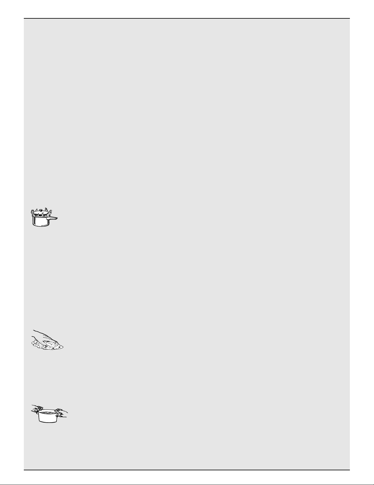
WARNING—TO REDUCE THE RISK
OF A COOKTOP GREASE FIRE:
A. Keep fan, filters and grease laden surfaces clean.
B. Always turn vent ON when cooking at high heat.
C.
Use high settings on cooktop only when necessary.
Heat oil slowly on low to medium setting.
D.
Don’t leave the cooktop unattended when cooking.
E. Always use cookware and utensils appropriate
for the type and amount of food being prepared.
CAUTION—For General Ventilating Use Only.
Do Not Use To Exhaust Hazardous Or Explosive
Materials and Vapors.
Using Your Cooktop
• Do not leave children alone or unattended
where a cooktop is hot or in operation. They
could be seriously burned.
•
CAUTION: Items of interest to children should
not be stored in cabinets above a cooktop—
children climbing on the cooktop to reach items
could be seriously injured.
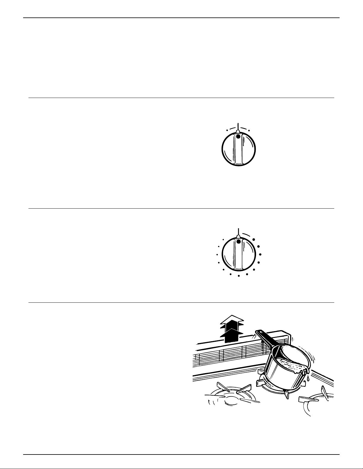
• When raising or lowering the vent: Keep
fingers away from all vent parts; assure that
cookware, pans and handles will not be struck
and tipped when raising the vent.
• Do not operate or clean your cooktop if the
glass is broken or cracked. Cleaning solutions
and spillovers could penetrate the broken cooktop
and create a risk of electric shock. Call for service
immediately if the cooktop glass breaks or cracks.
• Clean the cooktop with caution. If a wet sponge
or cloth is used to wipe spills on a hot cooktop be
careful to avoid steam burns.
4