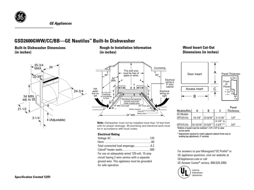
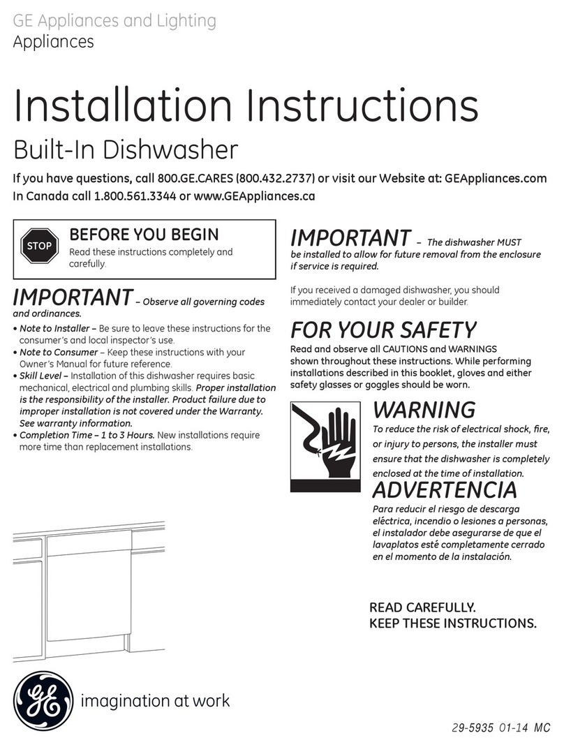
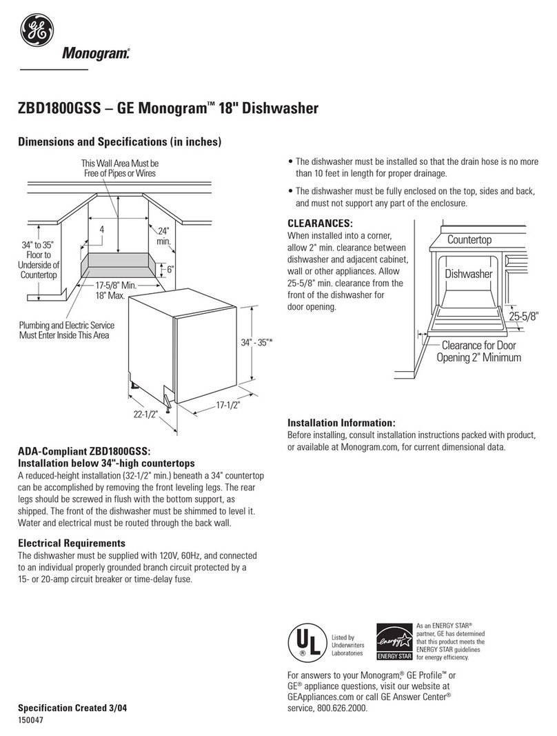
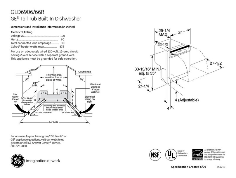
GE Profile PDW8200 Series How to use

PUB # 31-9102 02/03
MODEL SERIES:
TECHNICALSERVICE GUIDE
GE Consumer Products
Profile Dishwashers
PDW8200
PDW8260
PDW8400
PDW8480
PDW8500
PDW8600
PDW8680

IMPORTANT SAFETY NOTICE
The information in this service guide is intended for use by
individuals possessing adequate backgrounds of electrical,
electronic, and mechanical experience. Any attempt to repair a
major appliance may result in personal injury and property
damage. The manufacturer or seller cannot be responsible for the
interpretation of this information, nor can it assume any liability in
connection with its use.
WARNING
Toavoidpersonalinjury,disconnectpowerbeforeservicingthisprod-
uct. If electrical power is required for diagnosis or test purposes,
disconnect the power immediately after performing the necessary
checks.
RECONNECT ALL GROUNDING DEVICES
If grounding wires, screws, straps, clips, nuts, or washers used to
complete a path to ground are removed for service, they must be
returned to their original position and properly fastened.
GE Consumer Products
Technical Service Guide
Copyright © 2003
Allrightsreserved.This serviceguide maynot bereproduced inwhole orin part
inanyform without writtenpermissionfrom theGeneralElectric Company.

– 1 –
TABLE OF CONTENTS
Active Vent............................................................................................................ 26
Bottom Door Seal................................................................................................. 17
Calrod® Heating Element ...................................................................................... 23
Circulation System ...............................................................................................20
Component Locator Views .....................................................................................8
ControlModule .....................................................................................................14
Control Panel Features ..........................................................................................5
Cycle Progression Chart ...................................................................................... 31
Detergent/Rinse Module .......................................................................................14
Dishwasher Components ................................................................................... 12
Door Components................................................................................................ 12
Door Interlock Switch ...........................................................................................16
Door Panel ...........................................................................................................12
Drain System .......................................................................................................18
Escutcheon Keypad Assembly.............................................................................13
Factory Test Mode ................................................................................................ 29
FillFunnel .............................................................................................................23
Flashing Display Lights ........................................................................................27
Introduction............................................................................................................ 2
Nomenclature ........................................................................................................ 3
ServiceMode........................................................................................................28
Stainless Steel Bowed Panel (on some models).................................................. 15
Turbidity Sensor ...................................................................................................24
Warranty.................................................................................................................4
Washability Complaints ........................................................................................30
Water Valve and Flood Switch..............................................................................25
Wiring Diagram ....................................................................................................32

– 2 –
Introduction
The new GE Profile Stainless Steel Dishwashers are packed with features to get your dishes
cleaner, pots and pans spotless, and to keep your kitchen quieter. With a low power usage of 477
kW-hr/yr, they have an “EnergyStar” rating.
The GE Profile Stainless Steel Dishwashers have three wash arms that provide complete
coverage, eliminating pre-rinsing, soaking, and scrubbing. The ExtraCleanTM sensor incorporates a
thermistor Auto Temp control and measures the water turbidity in five levels of cleanliness. The
100% triple-water filtration, with extra fine filter, eliminates recirculating food particles. The
PiranhaTM hard food disposer grinds and pulverizes any other food particles.
GE Profile Stainless Steel Dishwashers run quieter, thanks to our QuietPowerTM motor, Stainless
Steel tub, and the QuietPower IV sound insulation, Thinstall.
The dual-wattage Calrod®heater draws 835 W when it is wet to heat the water faster and, during
the drying cycle, drops to 700 W for gentler drying.
The information on the following pages will help you service these new GE Profile Stainless Steel
Dishwashers effectively and efficiently.

– 3 –
Model Designator
Designates features – the higher
the number, the more features.
Nomenclature
The letter designating
theyearrepeatsevery
12 years.
Example:
T - 1974
T - 1986
T - 1998
P D W 8 6 8 0 G 0 0 W W
Brand
P = Profile
E = General Electric - NATM
G = General Electric
Product Type
CD - Counter Top DW = Dishwasher
SD = Standard SC = Convertible
SM = Spacemaker SS = Compact (18 in.)
RF = Retrofit HD = Home Depot Derivative
Exterior Color
BB = Black
CC = Bisque
SS = Stainless Steel
WW = White
Model Year Designator
Engineering Model Suffix
Nomenclature
Model Number
The serial plate of your
dishwasher is located on the
tub wall just inside the door.
Serial Number
The first two characters of the serial number identify
the month and year of manufacture.
Example: AA123456S=January,2001
A-JAN 2005 - H
D - FEB 2004 - G
F - MAR 2003 - F
G - APR 2002 - D
H-MAY 2001 - A
L - JUN 2000 - Z
M - JUL 1999 - V
R - AUG 1998 - T
S - SEP 1997 - S
T - OCT 1996 - R
V - NOV 1995 - M
Z - DEC 1994 - L
Note: The service information sheet is located under
the control panel.

– 4 –
Warranty
What GE Will Not Cover:
For The Period Of: GE Will Replace:
One Year Any part of the dishwasher which fails due to a defect in materials or workmanship. During
From the date of the this full one-year arranty, GE will also provide, free of charge, all labor and in-home service
original purchase to replace the defective part.
Second Year Any part of the dishwasher which fails due to a defect in materials or workmanship. During this
From the date of the second-year limited arranty, you will be responsible for any labor or in-home service costs.
original purchase
Five Years The dish asher racks or the electronic control module if they should fail due to a defect in
From the date of the materials or workmanship. During this five-year limited arranty, you will be responsible
original purchase for any labor or in-home service costs.
Lifetime of Product The Stainless tub or door liner, if it fails to contain water due to a defect in materials or
workmanship. During this full arranty, GE will also provide, free of charge, all labor and
in-home service to replace the defective part.
GE Dish asher Warranty.
■Service trips to your home to teach you how to use
the product.
■Improper installation.
■Failure of the product if it is abused, misused, or used for
other than the intended purpose or used commercially.
■Replacement of house fuses or resetting of circuit
breakers.
■Damage to the product caused by accident, fire, floods
or acts of God.
■Incidental or conse uential damage caused by possible
defects with this appliance.
■Cleaning or servicing of the air gap device in the
drain line.
This warranty is extended to the original purchaser and any succeeding owner for products purchased for home
use within the USA. Proof of original purchase date is needed to obtain service under the warranty. In Alas a, the
warranty excludes the cost of shipping or service calls to your home.
Some states do not allow the exclusion or limitation of incidental or consequential damages. This warranty gives
you specific legal rights, and you may also have other rights which vary from state to state. To now what your
legal rights are, consult your local or state consumer affairs office or your state’s Attorney General.
Warrantor: General Electric Company. Louisville, KY 40225
All warranty service provided by our Factory Service Centers,
or an authorized Customer Care
®
technician. To schedule service,
on-line, 24 hours a day, visit us at GEAppliances.com, or call
800.GE.CARES (800.432.2737).
Staple your receipt here.
Proof of the original purchase
date is needed to obtain service
under the warranty.
– 5 –
Control Panel Features
Throughout this manual, features and appearance may vary from your model.
Control Settings
Status Indicator Lights
The Status display tells you what’s happening while the dishwasher is in operation and may flash,
indicating a malfunction (see page 6). The lights will come
ON
indicating the sequence of
operation the dishwasher is in.
SENSING Displayed while the ExtraClean™ Sensor is measuring the amount of soil and temperature of water.
The dishwasher will adjust the selected cycle to achieve optimal performance.
WASHING Displayed during prewash and main wash periods.
RINSING Displayed during rinse periods.
DRYING Displayed during
HEATED DRY
.
SANITIZED Displayed when cycle has met sanitization conditions. Light remains
ON
until door is opened.
CLEAN Displayed when a wash cycle is complete. The light will remain
ON
until door is opened.
Time Remaining Display
(on some models)
Displays the minutes remaining until the cycle is complete. The display may adjust the remaining
time while the Sensing light is on.
Selections
The light above the selected pad will be ON to indicate which WASH CYCLE has been selected.
ANTI-BACTERIA Heavy 10.0 gal., 93 min.
Medium 8.6 gal., 90 min.
Light 7.2 gal., 90 min.
This cycle raises the water temperature in the final rinse to sanitize your dishware. The cycle
length will vary depending on the temperature of your inlet water.
NOTE: The Anti-Bacteria cycle is monitored for sanitization requirements. If the cycle is
interrupted during or after the main wash portion or if the incoming water temperature is so low
that adequate water heating cannot be achieved, the sanitizing conditions may not be met. In
these cases, the sanitized light will not illuminate at the end of the cycle.
NOTE: NSF certified residential dishwashers are not intended for licensed food establishments.
1
2
1 6
2
453
3
8
TIME REMAINING

– 6 –
COOK Heavy 11.4 gal., 95 min.
WARE Medium 10.0 gal., 71 min.
Light 10.0 gal., 66 min.
This cycle is meant for heavily soiled dishes or cookware with dried-on or baked-on soils. This
cycle may not remove burned-on foods. Everyday dishes are safe to be used in this cycle.
NORMAL WASH Heavy 9.9 gal., 74 min.
Medium 7.0 gal., 61 min.
Light 5.6 gal., 48 min.
This cycle is for medium/heavily soiled dishes and glassware.
SPEED CYCLE Heavy 9.3 gal., 36 min.
Medium 7.2 gal., 36 min.
Light 5.7 gal., 33 min.
This cycle is for everyday dishes and glassware.
CHINA CRYSTAL Heavy 10.0 gal., 49 min.
Medium 7.2 gal., 36 min.
Light 7.2 gal., 36 min.
This cycle is for lightly soiled china and crystal.
GLASSES Heavy 10.0 gal., 45 min.
(on some models) Medium 7.2 gal., 33 min.
Light 7.2 gal., 32 min.
This cycle is specifically designed for glasses.
RINSE ONLY Heavy 2.9 gal., 7 min.
Light 1.4 gal., 3 min.
For rinsing partial loads that will be washed later. Do not use detergent with this cycle.
NOTE:
This dishwasher is equipped with an ExtraClean™Sensor with automatic temperature
control; therefore cycle length and time may vary depending on soil and temperature conditions.
NOTE:
Only the Anti-Bacteria cycle has been designed to meet the requirements of Section 6,
NSF 184 for soil removal and sanitization efficacy
.
Enhancements
The light above the selected pad will be ON to indicate which ENHANCEMENT has been selected.
PRE For use with heavily soiled and/or dried-on, baked-on soils. This option
MUST
be selected
WASH
PRIOR
to starting the cycle.
This option adds 16 minutes to the cycle time. NOTE:
Cannot
be selected with
RINSE ONLY
cycle.
HEATED DRY Shuts off the drying heat option. Dishes air dry naturally and energy is saved. For faster air dry,
Light OFF
you can prop the door open after the
CLEAN
light illuminates.
HEATED DRY Turns the heater on for fast drying. This will extend the time to your wash cycle by 8 minutes
Light ON
for the
SPEED CYCLE
and 20 minutes for all other cycles.
NOTE:
Cannot be selected with
RINSE ONLY
cycle.
LOCK
You can lock the controls to prevent any selections from being made. Or you can lock the
controls after you have started a cycle.
Children cannot accidentally start dishwasher by touching pads with this option
selected.
To unlock the dishwasher controls, press and hold the
HEATED DRY
pad for 3 seconds. To lock
the dishwasher, press and hold the
HEATED DRY
pad for 3 seconds. The light above the
LOCK
pad will turn off.
ADDED HEAT When selected, the
NORMAL WASH
cycle will run longer with heating elements on to
improve both wash and dry performance.
NOTE:
Cannot be selected with
RINSE ONLY
cycle.
4

– 7 –
Start
Close the dishwasher door and select the
cycle and desired enhancements. Touch the
START/RESET
pad to begin the cycle. Water fill
begins, and approximately 60 seconds later the
wash action begins.
NOTE:
The dishwasher remembers your last cycle so
you don’t have to reprogram each time. When the
dishwasher door is fully closed, the control panel
lights will display the last settings you selected.
If you don’t want to change any of the settings,
simply touch the
START/RESET
pad to begin the
cycle.
If the door is closed the indicator lights will turn off
if the
START/RESET
pad is not selected within two
minutes. To activate the display, open and close the
door or press any pad.
Also, if a power failure occurs,
NORMAL
and
HEATED
DRY
will automatically be programmed. Make any
new selections and touch the
START/RESET
pad to
begin the cycle.
Clean
The
CLEAN
light is illuminated when a wash cycle is
complete. The light will stay
ON
until the door is
opened.
5
6
DELAY HOURS You can delay the start of a wash cycle for up to 9 hours (on some models). Press the
DELAY
HOURS
pad to choose the number of hours you want to delay the start of the cycle, then press
START/RESET
. The machine will count down and start automatically at the correct time.
Pressing
START/RESET
a second time will cancel the
DELAY START
selection.
NOTE:
If you forget to fully close the door a reminder signal will beep until you do so.
RESET To change a cycle after washing starts, touch the
START/RESET
pad to cancel the cycle.
The
START/RESET
light will flash while the water is pumped out if needed. This takes
approximately 90 seconds. When the light stops flashing, the dishwasher can be reprogrammed
and restarted.

– 8 –
Component Locator Views
Door View (Door Panel and Escutcheon Keypad Assembly Removed)
ControlModule
Flapper(ActiveVent)
House Electrical Supply Junction Box
Detergent/
RinseModule
DoorInterlock
Switch
VentDriver (ActiveVent)
FloodSwitch CirculationPump

– 9 –
FloodSwitch CirculationPump
Motor JunctionBox
Turbidity
Sensor
Sump
HighDrain Loop
DrainPump
DrainLine
CheckValve
WaterValve
Bottom View
Heating
Element
Retaining
Nuts
Escutcheon
KeypadAssembly
ActiveVent LatchHandle ControlModule
Door View (Door Panel Only Removed)
FrontofWasher
Back of Washer

– 10 –
Inside View
Inside
Door View
Detergent/Rinse
Module
Detergent
Compartment
Vent(Active
Vent)
UpperSprayArm
MainConduit
LowerSprayArm
FineFilter
Calrod®
HeatingElement
Middle SprayArm Water
SupplyConnection
Hub

– 11 –
Side View
Water
Valve
DrainLine
CheckValve
FillFunnel
Fill
Hose
Door
Spring
DrainTube
Assembly

– 12 –
Dishwasher Components
Door Components
• Interlock Switch Assembly
• ControlModuleAssembly
• Flapper(ActiveVent)
• Detergent/RinseModule
• Harness
Door Panel
To Remove the Door Panel:
1. Open the dishwasher door to the fully open
position.
2. Remove 10 screws (5 screws per side) which
hold the outer panel to the door assembly. Be
careful not to remove the 4 screws (2 per side)
holding the escutcheon to the door assembly.
3. Slowly close the door.
4. Once the door is closed, remove the 2 screws
that connect the bottom of the outer door panel
to the hinge arms.
5. Carefully separate the outer door panel from
the inner door panel.
To access the active vent, flapper, and door
interlock switch, the escutcheon keypad assembly
must be removed (See Escutcheon Keypad
Assembly).
To Install the Door Panel:
1. Open the dishwasher door a few inches.
2. Lift the outer door panel up in the vertical
position and hang the outer panel over top of
the escutcheon.
3. Close the door and install the 2 screws that
connect the bottom of the outer door panel to
the hinge arms.
4. Open the dishwasher door to the fully open
position and hold the top of the outer door
panel in place.
5. Install the 10 screws (5 screws per side)
which hold the outer panel to the door
assembly.
Shown with escutcheon keypad assembly and door
panel removed.
Donotremove
these screws
fromeither
side.
DoorScrews
DoorScrews
Flapper
(ActiveVent)
Detergent
Module
InterlockSwitch
Assembly
Harness
ControlModule
Assembly

– 13 –
Escutcheon Keypad Assembly
The keypad and 2 ribbon cables are a permanent
part of the escutcheon and are replaced as a unit.
To Remove the KeypadAssembly:
Caution: After removing the screws from the
escutcheon keypad assembly, the assembly is
still attached to the control module by 2 ribbon
cables. Dropping or rough handling of the escutch-
eon will cause the ribbon cable to tear, and the
entire escutcheon keypad assembly will need to
be replaced.
1. Remove the outer door panel (see Door
Panel).
2. Open the door, support the escutcheon key
pad assembly,and remove the 4 screws (2
per side) from the back side of the escutcheon
keypad assembly.
3. Remove the 2 ribbon cable connectors from
the control module and remove the escutch-
eon keypad assembly.
To Replace the KeypadAssembly:
IMPORTANT: When reassembling, the active vent
flapper must be closed before the escutcheon
keypad assembly is installed. Close the active vent
flapper by turning the worm gear by hand. Failure
to do so will cause a misalignment and an in-
crease in noise level.
1. While supporting the escutcheon keypad
assembly, connect the 2 ribbon cable connec-
tors to the control module.
2. Open the door. Align the escutcheon and install
the 4 screws from the back side of the es-
cutcheon keypad assembly.
3. Install the outer door panel (see Door Panel).
ControlModule
Escutcheon KeypadAssembly
Escutcheon KeypadAssembly Screws (2 per side)
ActiveVent
WormGear

– 14 –
Control Module
To Remove the Control Module:
1. Remove the outer door panel (see Door
Components).
2. Remove the escutcheon keypad assembly
(see Escutcheon Keypad Assembly).
3. Unplug the connectors from the module.
4. Remove the single screw that secures the
module to the right side of inner door panel.
(The screw is located on the outside of the
inner door panel.)
5. Slide the module out.
To InstalltheControl Manual:
1. Plug connectors into control module.
2. Insert the tabs on the left side of the control
module into the slots on the inner door panel.
3. Install the single screw that secures the
module to the right side of inner door panel.
4. Install the escutcheon keypad assembly (see
Escutcheon Keypad Assembly).
5. Install the door panel (see Door
Components).
Detergent/Rinse Module
The door panel must be removed to access the
detergent/rinse module. See Door Components.
The detergent/rinse module can be activated using
service mode. See Service Mode.
The detergent/rinse module automatically dis-
penses both the detergent and the rinse agent at
the appropriate times. The module is activated 2
times during a wash cycle.
The first time the module is activated (1), the lever
slides up the right-hand path of the connecting rod.
This action releases the detergent cover. When
deactivated (2), the lever returns down the left-
hand path and comes to rest under the notch in
the center of the connecting rod.At the second
activation (3), the lever lifts the connecting rod by
the notch. This action lifts the rinse dispenser
plunger and releases the rinse agent. When
deactivated, the lever returns to its original starting
position.
Cover
latch
Pre-wash
section
Main
wash
section
Cover
Indicator
window Dispenser cap
Rinse
agent
adjuster
123
L1 Voltage from J2-6
SingleScrew2Tabs
Factory Test Cable Port
J2-6 RY WR
1200-2800
DETERGENT MODULE
NO N
COM
WX
DOOR
INTERLOCK

– 15 –
Do not remove
this screw from
either side.
Stainless Steel Bowed Panel (on some
models)
To Remove the Bowed Panel:
1. Open the dishwasher door to the fully open (89
degrees open) position.
2. Remove 8 screws (4 screws per side) which
hold the outer panel to the door assembly. Be
careful not to remove the 2 screws which hold
the escutcheon to the door assembly.
3. Slowly close the door.
4. Once the door is closed, remove the 2 screws
that connect the bottom of the outer panel to
the hinge arms.
5. While holding the outer panel against the door
assembly, slowly open the door to about 15
degrees open so the top of the outer panel is in
front of the kitchen countertop. If the dish-
washer is not installed, the door does not have
to be opened.
6. Rotate the bottom of the outer panel out such
that the panel is now vertical.
7. Lift up on the stainless steel outer panel such
that top corner flanges lift up over the corner
cutouts in the escutcheon. Move the panel
forward and over the escutcheon so that the
panel is totally separated from the door. (See
photos of escutcheon and outer panel below.)
To Install the Bowed Panel:
1. Open the door to about 15 degrees open so
that the top of the outer panel is in front of the
kitchen countertop. If the dishwasher is not
installed, the door does not have to be opened.
2. Lift the outer panel up in the vertical position
and hang the outer panel over top of the
escutcheon. Take care to ensure that the
stainless steel panel corner flanges go over
and around the escutcheon corner cutouts.
3. While holding the outer panel to the escutch-
eon, slowly close the door.

– 16 –
4. With the panel hanging over the escutcheon,
rotate the bottom of the stainless steel outer
panel back so it is flush with the door assem-
bly. Make sure that the sides of the outer panel
fit around the hinge arms.
5. Look at the fit between the escutcheon and the
stainless steel outer panel front opening. Make
sure that the protruding ribs from the escutch-
eon fit inside the stainless steel front opening.
Adjust the position of the outer panel up or
down, left or right to center the panel with the
escutcheon.
6. Once the panel is centered, install the 2
screws in the bottom of the panel to connect
the stainless steel outer panel to the hinge
arms. Recheck to make sure the escutcheon
ribs are protruding through the panel opening.
7. While holding the outer panel against the door
assembly, slowly open the door to about 45
degrees open so that the remaining 8 panel
screws can be installed (4 screws on each
side).
Door Interlock Switch
The door interlock switch opens the L1 circuit and
Neutral circuit when the door is open.
Caution: After removing the screws from the
escutcheon keypad assembly, the assembly is
still attached to the control module by 2 ribbon
cables. Dropping or rough handling of the escutch-
eon will cause the ribbon cable to tear, and the
entire escutcheon keypad assembly will need to
be replaced.
1. Remove the escutcheon keypad assembly
(see Escutcheon Keypad Assembly).
2. Remove 2 screws and the switch from the
door.
3. Carefully remove the cover from the switch
and unplug the blade connectors.
Note: The wire color code is on the switch cover.
2 Screws
BXBW
BW
BX
NO COM
J2-7
J2-8
J1-3
J1-1
NO
N
L1
COM
WX DOOR WR
DOOR
DOOR INTERLOCK SWITCH

– 17 –
Bottom Door Seal
Thebottom door seal islocatedonthebottom of the
innerdoorpanel. Itissecuredtothe inner doorpanel
by three 1/8-in. pop rivets.
NOTE:A pop rivet tool, an 1/8- in. drill bit, and a
power drill are required to remove and install the
door seal. If pop rivets are unavailable, #8 x 3/8 in.
stainless steel sheet metal screws can be used.
To Remove Bottom Door Seal
1. Remove lower rack from dishwasher.
2. Remove the outer door panel (see Door
Panel).
3. Remove the white foam block that covers the
wiring harness.
4. Open the inner door panel a few inches.
5. Remove the 4 hinge screws (2 on each side)
that connect the hinge arms to the inner door
panel.
6. Pull each hinge arm forward (one at a time)
while sliding the bottom corners of the inner
door panel out (see photo).
7. After the inner door panel is clear from the
hinge arms, turn the inner door panel upside
down and place it on the floor with the control
panel facing toward the dishwasher (see
photo).
8. Drill out the 3 pop rivets with the 1/8-in. drill bit.
9. Remove the old door seal.
To Install Bottom Door Seal
1. Place the new door seal over the lip at the
bottom of the inner door panel and line up the
corresponding holes.
2. Install new pop rivets, or if pop rivets are
unavailable, install the #8 x3/8-in. stainless
steel sheet metal screws.
3. Turn the inner door panel right-side up with the
control panel facing outward.
4. Pull each hinge arm forward (one at a time)
while sliding the bottom corners of the inner
door panel into place.
5. Reinstall the 4 hinge screws (2 on each side)
that connect the hinge arms to the inner door
panel.
6. Place the white foam block over the wiring
harness and reinstall the outer door panel (see
Door Panel).
DoorSeal
ControlPanel
PopRivets
HingeScrews HingeArm
Foam Block
Dishwasherdoorshownupsidedown
BottomofDoor

– 18 –
Drain System
The drain system consists of the following compo-
nents:
• Inlet cover (sump filter is under inlet cover)
• Sump
• Drain pump (includes motor and one-way
check valve)
• Drain pipe
• Check valve (in line with drain pipe)
The inlet cover prevents large particles from
entering the sump. Water entering the drain pump
is not filtered by the fine filter (metal) or by the
sump filter (plastic). The drain pump is mounted
on the sump and contains a one-way check valve.
The drain pump is controlled by the control module
and can be activated using service mode (see
Service Mode). The drain pump pushes the drain
water out into the drainpipe. The drainpipe con-
tains a one-way check valve.
Inlet Cover and Sump
Caution: Use care to avoid breaking the clip on
the hub when removing the main conduit from hub.
Remove the lower wash arm and main conduit to
gain access to the inlet cover and sump.
Drain Pump
The dishwasher must be removed from its instal-
lation to gain access to the drain pump. The drain
pump can be activated using service mode (see
Service Mode). The drain pump contains a one-
way check valve. Refer to schematic or strip
circuit for motor resistance value.
Drain Pipe and Check Valve
The dishwasher must be removed from its instal-
lation to gain access to the check valve that is in-
line with the drainpipe.
L1 Output from J2-5
DRAIN PUMP
J2-5
M
RX WR
30 NO N
COM
WX
DOOR
INTERLOCK
Drain Pump
Inlet
Outlet
Sump
In-Line Check Valve
Drain Pipe
Main Conduit
Fine Filter
Hub
Inlet Cover
Other manuals for Profile PDW8200 Series
2
This manual suits for next models
6
Table of contents
Other GE Dishwasher manuals

GE
GE Profile PDW8900 Series User manual

GE
GE GLDA690PWW - 24-in Tall Tub Dishwasher Assembly instructions

GE
GE Cafe CDWT280VSS Assembly instructions

GE
GE GSC3200J User manual

GE
GE GSM2100 User manual

GE
GE GSM1800JBB - Spacemaker 18" Dishwasher User manual

GE
GE Monogram ZBD0700 User manual

GE
GE Triton XL GSD6200GCC User instructions

GE
GE GHDA690P User manual

GE
GE GDF 570 Series User manual