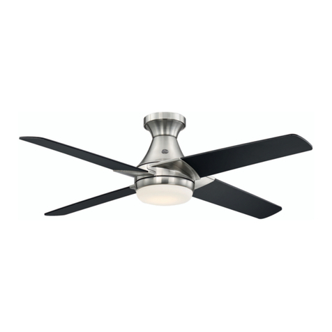
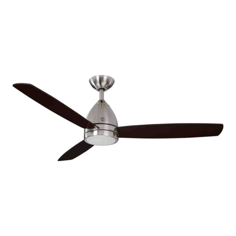
GE Savanna III User manual

Note: Installation videos for GE fans with SkyPlug technology
can be viewed and downloaded on www.gelightingandfans.com
Contact a qualified electrician or call the Customer Care Service Team at 1-866-885-4649
Customer Service hours of operation are 9:00AM-5:00PM EST -Monday-Friday
120V 60Hz, MADE IN CHINA
Customer Assistance
1-866-885-4649
1.32 m (52 in.)
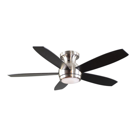
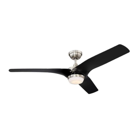
Savanna III LED Ceiling Fan
MODEL: 21243
ITM./ART.1162881
User Manual

Safety Rules
1
READ AND SAVE THESE INSTRUCTIONS
1. To reduce the risk of electric shock, ensure electricity has
been turned off at the circuit breaker or fuse box before
beginning.
WARNING: To reduce the risk of
fire, electric shock or personal
injury, mount fan to outlet box
marked acceptable for fan
support with the screws
provided with the outlet box.
WARNING: To reduce the risk
of personal injury, do not bend
the blade arms (also referred
to as flanges), when installing
the brackets, balancing the
blades or cleaning the fan. Do
not insert foreign objects in-
between rotating fan blades.
WARNING: To reduce the risk of
fire, electric shock or personal
injury, mount to outlet box
marked “acceptable for fan
support of 15.9 kg (35 lb.) or
less” and use mounting screws
provided with the outlet box.
Most outlet boxes commonly
used for the support of light
fixtures are not acceptable for
fan support and may need to be
replaced. Due to the complexity
of the installation of this fan, a
qualified licensed electrician is
strongly recommended.
Min. 7ft/2.13m
Min. 30in/76cm
2. All electrical connections must be made in accordance
with local codes, ordinances and/or the National Electric
Code. Electrical installation should be performed by a
qualified licensed electrician.
3. WARNING: to reduce the risk of electrical shock or fire, do
not use this fan with any solid-state fan speed control device.
It will permanently damage the electronic circuitry.
4. CAUTION: To reduce the risk of personal injury, use only
the screws provided with the outlet box.
5. The weight of the fan is 6.7 kg (14.77 lb). The outlet box
and support structure must be securely mounted and capable
of reliably supporting a minimum of 15.9 kg (35 lb.). Use only
cUL Listed outlet boxes marked “FOR FAN SUPPORT.”
6. The fan must be mounted with a minimum of 2.1m (7 ft .)
clearance from the trailing edge of the blades to the floor.
7. Avoid placing objects in the path of the blades.
8. To avoid personal injury or damage to the fan and other
items, be cautious when working around or cleaning the fan.
9. Do not use water or detergents when cleaning the fan or
fan blades. A dry dust cloth or lightly damped cloth will be
suitable for cleaning.
10. After making electrical connections, spliced conductors
should be turned upward and pushed carefully up into
the outlet box. The wires should be spread apart with
the grounded conductor and the equipment-grounding
conductor on one side of the outlet box and ungrounded
conductor on the other side of the outlet box.
11. All screws must be checked and re-tightened where
necessary during installation.
12. This fan is suitable for room sizes up to 225 square feet
(20.9 square meters).

SAFETY TIPS
1. Before working on a circuit , go to the main service
panel and remove the fuse or turn off the breaker
that controls that circuit .
2
o
Max. 11
Downrod
Slope
2. Tape a sign to the panel warning others to leave
the circuit alone while you work.
3. Before touching any wire, use a voltage tester to
make sure it’s not live.
4. Whenever you check for voltage in a receptacle,
check both outlets; each may be controlled by
a separate wiring circuit .
5. When replacing fuses, turn off the main power
first . Make sure your hands and feet are dry, and
place one hand behind your back to prevent
electricity from making a complete circuit through
your chest. Touch a plug fuse only by its insulated
rim.
6. Remove cartridge fuses with fuse puller.
7. Use tools with insulated handles and ladders
made of wood or fiberglass.
8. To protect children, place safety cover over
any unused outlets.
9. Vaulted ceiling angle is not to exceed 11
degrees.

Tools Needed (Not Supplied)
3
Required
Flathead Screwdriver
(1# screwhead
recommended)
Philips Screwdriver Safety Glasses
Step Ladder Wire Stripper Soft Cloth

Carefully unpack and identify each part to make sure you have everything ready for installation.
Lay out each part on a clean area such as a table or floor. Check to make sure you have the
following:
Hardware Bag Blade Balancing Kit
x3 x2
x10
x2
x2 x2
x1
x2
4
Hardware Included

Carefully unpack and identify each part to make sure you have everything ready for installation.
Lay out each part on a clean area such as a table or floor. Check to make sure you have the
following:
SkyReceptacle
5
Package Contents
Light kit pan

Review important safety instructions before installation.
SkyReceptacle
SkyPlug
Outlet Box (not provided)
Ground Wire from Housing
Black Wire
Wood Screw
Neutral White Wire
Rubber Washer
Outlet Box Screw
Canopy Mounting Screw
Flat Washer
Push Lever
Canopy
Canopy Trim Ring
Downrod
Coupling Cover
3-Pin Connector-Male
Cotter Pin
Clevis Pin
Collar Set Screw
Motor Assembly
Blade Screw
Light Kit Pan
2-Pin Connector-Male
2-Pin Connector-Female
LED Light Kit
Shade
LED Light Kit Mounting Screw
Light Kit Pan Mounting Screw
Blade
3-Pin Connector-Female
6
Fan Installation Drawing

SkyReceptacle Typical Wire Configurations
TYPICAL WIRE CONFIGURATIONS:
Black(Live)
Black(Live)
Black(Live 1)
Red(Live 2)
White
White
White
Wire Nut
White
Green
Green
Green
WIRING DIAGRAM #1:
Typical Wiring
Configuration
for 1 Wall Switch
WIRING DIAGRAM #2:
Typical Wiring
Configuration
for 2 Wall Switches
WIRING DIAGRAM #3:
Wiring Configuration
with more than 1
of the same colored
wires in the outlet box
NOTE: If you do not have standard wiring configurations and have questions about the wiring in
your outlet box,please contact a qualified electrician, or call customer service 1-866-885-4649.
NOTE: If you have multiple wires connected together, add a jumper lead and insert jumper lead
into terminal. Only one single wire can be inserted into terminal.
View Installation Video@ www.gelightingandfans.com
7

SkyReceptacle Installation
4mm rubber washer
7mm rubber washer
7mm rubber washer
4mm rubber washer
0-1.5mm
0-1.5mm Gap
1.5-3mm Gap
>3mm Gap
>3mm
1.5-3mm
Important: Install SkyReceptacle with rubber washers to avoid a gap or uneven surface,
and to ensure proper placement of receptacle on the ceiling.
8

SkyReceptacle Installation
1/2"/12.7mm
Outlet Box
(not Supplied)
Sky
Receptacle
Insert wires into terminal, tighten
screw to secure wires.
Terminal’s Bottom view
on Sky Receptacle
1
9
2
OK
Not
OK
Not
OK

SkyReceptacle Installation
Using the rubber washer when installing receptacle ensures proper placement of the
receptacle on the ceiling
Rubber Washer
( Install cover plate if supplied )
not provided on all models
3
10

Fan Installation
4
5
Slide down trim ring from canopy.
Remove rubber inserts from canopy and discard.
11

Fan Installation
6
Press up on the push lever while lifting the
fan. For correct alignment , make sure the
bracket with plug and push lever is placed
between the receptacle bracket metal
slots ( in a "+ " formation ) as shown.
Initial "+" formation while
lifting fan and inserting
plug into receptacle
Receptacles Slots
Receptacles Slots
Bracket
with Push
Lever
Final formation after
turning fan
Insert the plug into
the receptacle, keeping
the lever pushed up while
turning fan to the right .
Let go of the push lever and
make sure plug is fully inserted
into receptacle. Continue to support
fan until locked into position.
12

7
8
9
Fan Installation
Once installed, tighten all 4 screws.
Reinstall trim ring, being careful not to depress the push lever.
Adjust fan housing so ball is properly seated in bracket .
13

10
11
12
Fan Installation
Install fan blades.
Install light kit pan.
Install LED light kit.
Install shade-turn to secure.
14

Fan Operation
15
Reverse Switch
Summer
Winter

5HPRWH&RQWURO
6
7KLVEXWWRQWXUQVWKHIDQ21RU2))
EXWWRQ
7KLVEXWWRQGHOD\VWKHOLJKWWXUQLQJRII
IRUDSSUR[LPDWHO\VHFRQGVHQDEOLQJ
\RXWRH[LW\RXUURRPEHIRUHWKHOLJKW
WXUQVFRPSOHWHO\RII
EXWWRQ
7KLVEXWWRQFRQWUROVWKHOLJKWDQGDOVR
FRQWUROVWKHEULJKWQHVVVHWWLQJ3UHVVDQG
UHOHDVHWKHEXWWRQWRWXUQWKHOLJKW21RU2))
3UHVVDQGKROGWKHEXWWRQWRVHWWKHGHVLUHG
EULJKWQHVVWKHOLJKWZLOOVORZO\LOOXPLQDWHWR
PD[LPXPOLJKWRXWSXWDQGWKHQVWRSZKHQ
KROGLQJWKHEXWWRQWKHQUHOHDVHWKHEXWWRQ
DQGKROGLWDJDLQXQWLOLWUHDFKHVPLQLPDO
LOOXPLQDWLRQZKHUHLWZLOODXWRPDWLFDOO\VWRS
DJDLQ7KHOLJKWEXWWRQKDVDQDXWRUHVXPH
LWZLOOVWD\DWWKHVDPHEULJKWQHVVDVWKH
ODVWWLPHLWZDVWXUQHGRII
/RZVSHHG
0HGLXPVSHHG
+LJKVSHHG
1RWH
.7RSUHYHQWGDPDJHWRWUDQVPLWWHUUHPRYHWKHEDWWHULHVLIQRWXVHGIRUORQJSHULRGV
.5HSODFHEDWWHULHVDVDVLPXOWDQHRXVVHW²DOZD\VUHSODFHWKHZKROHVHWRIEDWWHULHVDWRQHWLPHWDNLQJFDUHQRWWRPL[ROGDQGQHZRQHVRUEDWWHULHVRI
GLIIHUHQWW\SHV
.3OHDVHFRQWDFW\RXUORFDOEDWWHULHVUHF\FOLQJFHQWHUIRUSURSHUEDWWHU\GLVSRVDOLQIRUPDWLRQ
2SHUDWLRQLQGLFDWRU
5(027()81&7,216
/RFNXQORFNVZLWFK
ಯ2µDQG´,µGLPVZLWFK
)RUWKLVIDQWKHGLPVZLWFKVKRXOGEHLQWKH
´,µSRVLWLRQDOORZLQJIRUGLPPLQJRIWKHOLJKW
3ODFHWKHVZLWFKLQWKH´µSRVLWLRQWRWXUQWKH
GLPPLQJIHDWXUHRȺLI\RXGRQRWZDQWWKH
GLPPLQJIHDWXUH
´6\QFµEXWWRQ
7KLVEXWWRQDOORZVUHFHLYHUWRSDLUZLWKWKHFRGH
DVVLJQHGE\WUDQVPLWWHU
127()RUFRQYHQLHQFHWKHWUDQVPLWWHUKDVEHHQSUHVHW
E\IDFWRU\DQGLVSODFHGLQXQORFNSRVLWLRQLQLWLDOO\
7KHUHFHLYHUKDVEHHQSUHVHWZLWKDFRPPRQFRGH7KH
IDQLVUHDG\IRUXVH7KLVWUDQVPLWWHUFDQFRQWURODQ\IDQ
ZLWKWKLVVDPHLQLWLDOVHWWLQJ
,QWKHXQORFNSRVLWLRQ7KHWUDQVPLWWHUZLOOVHQGDFRPPRQFRGHWKLVWUDQVPLWWHUZLOORSHUDWHDOORWKHU*()$16ZLWKWKHVDPH
UHFHLYHUFRQ¿JXUDWLRQ%XWWKHFRQGLWLRQLVWKHUHFHLYHUKDYHEHHQSUHV\QFHGZLWKWKHFRPPRQFRGHRWKHUZLVHWKHIDQZLOOQRWZRUN
,QORFNSRVLWLRQ$OORZVDXQLTXHFRGHWREHVHQWWRWKHUHFHLYHULQWKHIDQ2QO\WKHUHFHLYHURIWKLVIDQZLOOEHV\QFHGZLWKWKLVWUDQVPLWWHULQ
ORFNSRVLWLRQ0RUHWKDQRQHIDQFDQEHV\QFHGZLWKRQHWUDQVPLWWHULQWKLVFDVHIROORZV\QFLQVWUXFWLRQIRUHDFKIDQ
&KDQJLQJWKHXORFNORFNSRVLWLRQZLOOFDXVHWKHFRGHWRFKDQJHDQGWKHUHFHLYHUZLOOQHHGV\QFKURQL]LQJDJDLQWRKDYHWKHVDPHFRGHDVWKH
WUDQVPLWWHU
/RFNXQORFNVZLWFKZKHQSODFHGLQWKHXQORFNSRVLWLRQDOORZVDFRPPRQFRGHWREHVHQW

5HPRWH&RQWURO
7
5(027(&21752/23(5$7,216
6WHS5HVWRUHSRZHUWRFHLOLQJIDQ
6WHS,QVWDOOWZRYROW$$$EDWWHULHV,SURYLGHG.
6WHS3UHVVWKH´µEXWWRQORFDWHGRQWKHIURQW
RIWKHWUDQVPLWWHUWRRSHUDWHWKHIDQ
6WHS3UHVVWKH´µEXWWRQWRRSHUDWHWKHOLJKW
$GLPPHUIHDWXUHLVSURYLGHGRQWKHOLJKW
3UHVVDOOWKHZD\GRZQWRJHWPD[LPXPOLJKW
2SHUDWH)DQXVLQJ7UDQVPLWWHU&RGH3UH6HWE\)DFWRU\
6WHS6ZLWFKRȺWKHSRZHURIWKHIDQ
6WHS6ZLWFKRQWKHSRZHURIWKHIDQ
6WHS:LWKLQVHFVZLWFKWKHORFNXQORFN
VZLWFKRQWKHEDFNRIWKHWUDQVPLWWHUWRORFNSRVLWLRQ
DQGWKHQSXVKWKHV\QF´µEXWWRQIRUDERXW
VHFXQWLOWKHIDQOLJKWNLWÀDVKHVWLPHV
,Q&DVH2I,QWHUIHUHQFHZLWK6HYHUDO)DQV<RX&DQ
&KDQJHWKH7UDQVPLWWHU&RGHWR2SHUDWH7KLV)DQ2QO\
,&$)$1763
7KLVGHYLFHFRPSOLHVZLWK566,VVXH2SHUDWLRQLVVXEMHFWWRWKHIROORZLQJWZRFRQGLWLRQV
7KLVGHYLFHPD\QRWFDXVHKDUPIXOLQWHUIHUHQFHDQG
WKLVGHYLFHPXVWDFFHSWDQ\LQWHUIHUHQFHUHFHLYHGLQFOXGLQJLQWHUIHUHQFHWKDWPD\FDXVHXQGHVLUHGRSHUDWLRQ
&$87,21$Q\FKDQJHVRUPRGL¿FDWLRQVQRWH[SUHVVO\DSSURYHGE\WKHSDUW\UHVSRQVLEOHIRUFRPSOLDQFHFRXOGYRLGWKHXVHU·VDXWKRULW\
WRRSHUDWHWKHHTXLSPHQW
1RWH7KLVHTXLSPHQWKDVEHHQWHVWHGDQGIRXQGWRFRPSO\ZLWKWKHOLPLWVSXUVXDQWWR566,VVXH
7KHVHOLPLWVDUHGHVLJQHGWRSURYLGHUHDVRQDEOHSURWHFWLRQDJDLQVWKDUPIXOLQWHUIHUHQFHLQDUHVLGHQWLDOLQVWDOODWLRQ7KLVHTXLSPHQWJHQHUDWHV
XVHVDQGFDQUDGLDWHUDGLRIUHTXHQF\HQHUJ\DQGLIQRWLQVWDOOHGDQGXVHGLQDFFRUGDQFHZLWKWKHLQVWUXFWLRQVPD\FDXVHKDUPIXOLQWHUIHUHQFH
WRUDGLRFRPPXQLFDWLRQV+RZHYHUWKHUHLVQRJXDUDQWHHWKDWLQWHUIHUHQFHZLOOQRWRFFXULQDSDUWLFXODULQVWDOODWLRQ,IWKLVHTXLSPHQWGRHVFDXVH
KDUPIXOLQWHUIHUHQFHWRUDGLRRUWHOHYLVLRQUHFHSWLRQZKLFKFDQEHGHWHUPLQHGE\WXUQLQJWKHHTXLSPHQWRȺDQGRQWKHXVHULVHQFRXUDJHGWRWU\
WRFRUUHFWWKHLQWHUIHUHQFHE\RQHRUPRUHRIWKHIROORZLQJPHDVXUHV
5HRULHQWRUUHORFDWHWKHUHFHLYLQJDQWHQQD
,QFUHDVHWKHVHSDUDWLRQEHWZHHQWKHHTXLSPHQWDQGWKHUHFHLYHU
&RQQHFWWKHHTXLSPHQWLQWRDQRXWOHWRQDFLUFXLWGLȺHUHQWIURPWKDWWRZKLFKWKHUHFHLYHULVFRQQHFWHG
&RQVXOWWKHGHDOHURUH[SHULHQFHGUDGLR79WHFKQLFLDQIRUKHOS

Remote Control Pairing Instructions
REMOTE CONTROL PAIRING INSTRUCTIONS:
Important Note : By default , every fan has been pre-programmed at the factory and should be
fully functional once installation is completed. There is no need to perform the pairing process.
Make sure all wiring connections have been properly made and are secure.
Make sure batteries are installed correctly in the transmitter.
Make sure batteries have a full charge or replace with new batteries.
Make sure all switches of the power supply to the fan motor are turned on.
Should you find the fan or remote control not working or not fully functional after installation or during
use, pairing of the remote control can be done by following the below simple procedures.
Note, however, that there could be other reasons as to why a fan or a remote control is not working:
PROCEDURES FOR PAIRING RECEIVER AND TRANSMITTER:
The remote is not functioning properly, and you want to reset a fan remote control, or
You are replacing the original transmitter or receiver, or
You have multiple ceiling fans of the same model in one location and you wish to be able to control them
with one remote.
IF USING ONE REMOTE CONTROL TO CONTROL MULTIPLE FANS
1. Turn OFF the power/isolation switch to ALL fans that you would like to program to the same
hand held remote.
2. Remove the battery cover to access the "Sync" switch on the hand held remote.
3. Install two 1.5 V AAA batteries and make sure the polarity of the batteries is correct .
4. Turn on the power/isolation switch to ALL fans.
5. Press the "Sync" switch with the corner of the battery cover (you can also use a small screwdriver
or ballpoint pen) to change the frequency settings within 30 seconds after restoring the power.
The lights will ash (on/o ) 3 times and remain bright , then the pairing process is complete.
6. Try different speed settings on the transmitter to ensure all the fans are now fully functional. If not ,
repeat the process starting from Step 1 again.
TO RESET INDIVIDUAL REMOTE CONTROL FOR EACH FAN/INSTALLING A NEW RECEIVER
Note: If you have more than one fan of the same model but wish to only perform the pairing on
one fan, follow the same steps starting from step 1 to step 6. Make sure to only power ON one
fan at a time, and power OFF all the nearby fans to avoid picking up the same signal.
1. Turn OFF the power/isolation switch to the fan.
2. Remove the battery cover to access the "Sync" switch on the hand held remote.
3. Install two 1.5 V AAA batteries and make sure the polarity of the batteries is correct .
4. Turn on the power/isolation switch to the fan.
5. Press the "Sync" switch with the corner of the battery cover (you can also use a small screwdriver
or ballpoint pen) to change the frequency settings within 30 seconds after restoring the power.
The light will ash (on/o ) 3 times and remain bright, then the pairing process is complete.
6. Try dierent speed settings on the transmitter to ensure the fan is now fully functional. If not ,
repeat the process starting from Step 1 again.
18

Blade Wobble Balancing
Not OK
Not OK
OK
OK
OK
XY
A
B
C
X
X
Y 3mm / ⅛in.
Y 3mm / ⅛in.
-
-
<
>
19
This manual suits for next models
1
Table of contents
Other GE Fan manuals
Popular Fan manuals by other brands

Goldair
Goldair Platinum GPTF370 operating instructions

BlueChimney
BlueChimney BlueChimney User manual and installation guide

Hunter
Hunter Swanson installation manual

TJERNLUND
TJERNLUND DB-2 DUCT BOOSTER 8504030 REV B 0900 Owner's instructions

Hunter
Hunter 22388 Parts guide

Sterr
Sterr IDM operating instructions

Caframo
Caframo 797CA-GBX Instructions for use

Rosenberg
Rosenberg AND Ex Series Operating instruction

Craftmade
Craftmade Cameo CA60 installation instructions

Hunter
Hunter Caribbean Breeze 54094 Owner's guide and installation manual

emerio
emerio TFN-123015 instruction manual

Carlton
Carlton CSF403SS instruction manual